Quality 10Gb OM3 Fiber Cables

Status
Not open for further replies.
Joined
Nov 11, 2014
Messages
1,174
Maybe I'm stupid but I don't even quite get what you're asking. There already appears to be a fiber connecting those two, and of everything you've got there it's about the closest thing to an acceptably run fiber patch you have.

No you are not. Sometime I even confuse myself with my own question:smile:

Yes there is already connection there, but don't look pretty as the cat6 patch cables. The connection there has a fiber cable already in place but is too long , so in order no to stick too much to the front of the rack and hitting the door I move it to the side of the rack and secure there. I wish to replace is with fiber cable(as short as possible ) so it will make a nice small loop like the one I made with cat6 patch cables. I just don't know if I can bend the fiber calbe the same way I did with cat6 patch cable jumpers I made myself.
 

Mlovelace

Guru
Joined
Aug 19, 2014
Messages
1,111
I just don't understand the physical deference if order to determine is there trade of in going OM4. With Copper cables (cat5,cat6,cat7) I do understand the physical difference and I don't see any possible trade off, except the cable might get little bit more tough to work with.
OM3 – Laser-Optimized Multimode
  • Color – Aqua
  • Core Size – 50um
  • Date Rate – 10GB @ 850nm
  • Distance – Up to 300 meters
    • Uses fewer modes of light, enabling increased speeds
    • Able to run 40GB or 100GB up to 100 meters utilizing a MPO connector
  • Applications – Larger Private Networks
OM4 – Laser-Optimized Multimode
  • Color – Aqua
  • Core Size – 50um
  • Data Rate – 10GB @ 850nm
  • Distance – Up to 550 meters
    • Able to run 100GB up to 150 meters utilizing a MPO connector
  • Applications – High-Speed Networks – Data Centers, Financial Centers & Corporate Campuses
 
Joined
Nov 11, 2014
Messages
1,174
OM3 – Laser-Optimized Multimode
  • Color – Aqua
  • Core Size – 50um
  • Date Rate – 10GB @ 850nm
  • Distance – Up to 300 meters
    • Uses fewer modes of light, enabling increased speeds
    • Able to run 40GB or 100GB up to 100 meters utilizing a MPO connector
  • Applications – Larger Private Networks
OM4 – Laser-Optimized Multimode
  • Color – Aqua
  • Core Size – 50um
  • Data Rate – 10GB @ 850nm
  • Distance – Up to 550 meters
    • Able to run 100GB up to 150 meters utilizing a MPO connector
  • Applications – High-Speed Networks – Data Centers, Financial Centers & Corporate Campuses

Right , those are the specs. I am glad that the core size is the same , I was afraid about that part cause that will may have tradeoffs. It must be physically different in some way in order to be able to provide longer runs and faster speeds. Different glass inside perhaps ? That's what I meant with difference - the physical one.
 

jgreco

Resident Grinch
Joined
May 29, 2011
Messages
18,680
No you are not. Sometime I even confuse myself with my own question:)

Yes there is already connection there, but don't look pretty as the cat6 patch cables. The connection there has a fiber cable already in place but is too long , so in order no to stick too much to the front of the rack and hitting the door I move it to the side of the rack and secure there. I wish to replace is with fiber cable(as short as possible ) so it will make a nice small loop like the one I made with cat6 patch cables. I just don't know if I can bend the fiber calbe the same way I did with cat6 patch cable jumpers I made myself.

That whole setup, taken to its logical conclusion, will gravitate towards becoming a really unmanageable mess.

Now on one hand maybe you don't care, and if you don't care, I don't mind. But it feels like a failure to commit to a strategy. I'm not sure what the purpose of the 5448 sitting there is, but if you're going to go all 1:1 mini patches on the 5548, dude,

9ttnjhb.jpg


Go all out. :smile:

Now I have to say I'm not a fan of this strategy, but I cannot argue that it is anything other than a coherent and neat strategy for handling edge aggregation. It also logically follows that if you were to need to do a switch replacement, you would be disconnecting them all anyways, so this kind of thing doesn't actually violate the spirit of one of my cabling guidelines, which is that things shall not be strung such that removal of gear would be blocked by production network cabling. In this picture all the cables are downward, in yours they're actually in a better configuration (down and up) which is better because it means that you're never digging through a layer to get at an RJ45.

But that doesn't actually totally work out for you anyways. Try removing that Dell 5448 without disrupting anything else. See my point?

So you started out with a pretty interesting strategy. But the fiber thing. Bad. What is that, a Fujitsu switch in 37? Anyways what you've got there are some harp strings run between the 10G XFP switch and the top patch panel. Oh and ew no rack hardware for 37. Bleh! 'Cuz normally I'd suggest putting some cable management stuff in at 36, so that you could take your fiber down from the XFP ports, into something to guide it to the right hand side, and then you could run fiber up to the stuff you needed above. Cables should never fly over other equipment.
 

jgreco

Resident Grinch
Joined
May 29, 2011
Messages
18,680
Right , those are the specs. I am glad that the core size is the same , I was afraid about that part cause that will may have tradeoffs. It must be physically different in some way in order to be able to provide longer runs and faster speeds. Different glass inside perhaps ? That's what I meant with difference - the physical one.

You don't need to worry about this within a single rack or a home network.
 

jgreco

Resident Grinch
Joined
May 29, 2011
Messages
18,680
So you started out with a pretty interesting strategy. But the fiber thing. Bad. What is that, a Fujitsu switch in 37? Anyways what you've got there are some harp strings run between the 10G XFP switch and the top patch panel. Oh and ew no rack hardware for 37. Bleh! 'Cuz normally I'd suggest putting some cable management stuff in at 36, so that you could take your fiber down from the XFP ports, into something to guide it to the right hand side, and then you could run fiber up to the stuff you needed above. Cables should never fly over other equipment.

Also, is there some method to the madness in the allocation of ports on the XFP switch?
 
Joined
Nov 11, 2014
Messages
1,174
Here is more recent picture of the rack, that is taking care of two of the issues you mention:


I'm not sure what the purpose of the 5448 sitting there is,

No purpose but sitting there as storage. Only purpose is actually serving is to to support 5548 in case I need to replace it. So if I remove the front screws of 5548 it won't fall back cause it will have the 5448 underneath. Space in 39 is not practical for use anyways. Then I came up with the genius idea how to utilize the spot 39 with device that is usefully and same time don't need access to it's front - RPS720. Brilliant, right ?

Oh and ew no rack hardware for 37. Bleh!

That's how I felt about it. And after a year of struggling to fine a original rack mounting gear for it, I bought another Fujitsu (brand new) that came with everything , and now put the old one for sale. This tell you if I care about neatness or not.
So that is take care of now - Fujitsu is sitting on his own rails , not on top the old Dell server.(which was there only for that purpose.


For the dell 5548 and patch panels: I looked 1000's of rack pictures and I've given it a great deal of consideration how to do it, but as you point out if both panel are underneath the switch there will hard to remove individual cables and will add additional strain between cables. So I decide to go with the configuration 2 patch panes with switch in the middle to be the one make most sense for me.
P.S. If I was able to find(or make) a super-short patch cables , I would make same configuration without a gap between switch and patch panel , so I don't waste a that 1U space.


The fiber is where I think I need help with.
Originally I was thinking to use only the last 5 of top patch panel for fiber connections. (my patch panels are with keystones so I can easily put fiber, RJ45 ,coax , or anything that you can put on keystone jack.)
Now besides the fact that 5 might not be enough, the question is what is the optimal way to organize it ?

I don't want make everything from scratch, and in the same time I would appreciate any change you could suggest ?
 

Attachments

  • sDSC00045.jpg
    sDSC00045.jpg
    331 KB · Views: 311
Joined
Nov 11, 2014
Messages
1,174
Also, is there some method to the madness in the allocation of ports on the XFP switch?

:D
I tried to keep the cable stretched enough so it will not touch the rack front door. Port allocation on the switch totally depend on how long is the fiber cable: If is longer you go one position to left, if short you go one to the right. Just to keep tension same on all cables.

P.S. There is always a reason behind Black Ninja ideas.:)
 
Joined
Nov 11, 2014
Messages
1,174
So you started out with a pretty interesting strategy. But the fiber thing. Bad. What is that, a Fujitsu switch in 37? Anyways what you've got there are some harp strings run between the 10G XFP switch and the top patch panel. Oh and ew no rack hardware for 37. Bleh! 'Cuz normally I'd suggest putting some cable management stuff in at 36, so that you could take your fiber down from the XFP ports, into something to guide it to the right hand side, and then you could run fiber up to the stuff you needed above. Cables should never fly over other equipment.

By reading what you are saying it makes me think: You understand exactly what I had in mind, and exactly where I failed. If there is a solution at all, probably you are the only one who can find it.

P.S. I don't mean to discredit all the smart people in the forum who also might have good ideas, but it's not easy.
 
Joined
Nov 11, 2014
Messages
1,174
It's not easy because the goal is not just to "make it work". It's already working.

The goal is: How to make it clean, simple, reliable, serviceable, upgradable and working too. That's whats makes it hard.
 

jgreco

Resident Grinch
Joined
May 29, 2011
Messages
18,680
By the way if it isn't clear to you, none of what I say here about your rack is anything other than constructive criticism and discussion of ideas and concepts. It usually takes a certain kind of person with either a lot of discipline or OCD-ish tendencies to get to the point you have.

No purpose but sitting there as storage. Only purpose is actually serving is to to support 5548 in case I need to replace it. So if I remove the front screws of 5548 it won't fall back cause it will have the 5448 underneath.

Switches suck that way. Glad to know I'm not the only one it annoys.

Space in 39 is not practical for use anyways. Then I came up with the genius idea how to utilize the spot 39 with device that is usefully and same time don't need access to it's front - RPS720. Brilliant, right ?

I'll give it a "not bad." It's an efficient use of space, granted, but it violates my rule that equipment should be removable without having to de-cable other things. In this case: your switch and the cables from the bottom patch panel.

That's how I felt about it. And after a year of struggling to fine a original rack mounting gear for it, I bought another Fujitsu (brand new) that came with everything , and now put the old one for sale. This tell you if I care about neatness or not.
So that is take care of now - Fujitsu is sitting on his own rails , not on top the old Dell server.(which was there only for that purpose.

Um, okay. Would it maybe have been cheaper to get some generic 1U brackets and just drill them as needed?

http://www.ebay.com/itm/L-Brackets-...Compatible-with-Dell-HP-SA-3301-/161139639793
http://www.ebay.com/itm/Penn-Elcom-R1206-1U-Rack-Mount-Bracket-1U-/321724242100
etc

Or is it actually on some sort of rail set?

For the dell 5548 and patch panels: I looked 1000's of rack pictures and I've given it a great deal of consideration how to do it, but as you point out if both panel are underneath the switch there will hard to remove individual cables and will add additional strain between cables. So I decide to go with the configuration 2 patch panes with switch in the middle to be the one make most sense for me.
P.S. If I was able to find(or make) a super-short patch cables , I would make same configuration without a gap between switch and patch panel , so I don't waste a that 1U space.

You can make patch cables yourself if you want. It isn't as cheap as the prebuilts, but you can make them to quarter-inch lengths easily.

Get a box of quality Cat6 stranded cable. This is absolutely NOT the same stuff you use when wiring Keystone jacks, etc., which is solid core wire. Must be stranded. Try to find 550MHz stranded.
Get yourself a Platinum Tools EZ-RJ45 100054C crimper, a 15015 stripper, a Triplett cable shear, and a Klein VDV Scout Pro or something else to test basic connectivity/opens/shorts.
Then you need some strain reliefs such as the EZ-RJ45 100030GY, and some EZ-RJ45 crimps 100010C in the color of your choice.

There are a bunch of tutorials on the Internet about how to use the EZ-RJ45 stuff, most of them are fine, but the one thing is that I've rarely seen is a method to straighten the conductors that doesn't kill your fingers after about two connectors. My little contribution to the world is to use the rounded side edge on the 15015 to run the wires over several times and straighten them that way. :smile:

The downside to this is that it's suuuuuuuper-expensive to do the initial tool-up especially if you have any doubts as to whether or not you're going to be any good at making cables. If that's the case with you, contact me and maybe we can work something out.

The fiber is where I think I need help with.
Originally I was thinking to use only the last 5 of top patch panel for fiber connections. (my patch panels are with keystones so I can easily put fiber, RJ45 ,coax , or anything that you can put on keystone jack.)
Now besides the fact that 5 might not be enough, the question is what is the optimal way to organize it ?

I don't want make everything from scratch, and in the same time I would appreciate any change you could suggest ?

Well, I imagine the problem here is that you've got a home setup, so my natural inclination to separate fiber and copper and a bunch of other similar inclinations isn't appropriate to the discussion here. Am I right in guessing that this is all in the front side of your server rack? In some ways that makes this a little more difficult.

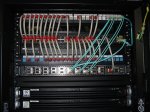
Can I fly off on a tangent here for a moment? One other thing I noticed was that you seem to maybe be doing this more for looks rather than for management/maintainability. In particular, I notice that you left switchports 21-24 empty, I'm guessing in a bid to "re-verticalize" your patches starting at #25-26. Most of us who professionally OCD over network wiring wouldn't do this because what we're actually optimizing for is manageability and maintainability, and the "looks nice" aspect comes in as a secondary benefit. Am I reading that correctly? There's absolutely no wrong answer to that question and I won't think less of you either way, but understanding the motivations behind what you've done so far may matter in trying to work out something intelligent and useful to say.

For discussion:

cable-management.png


So the goal here is to avoid crossing gear with cables. To do that, cable management stuff like the Panduit enclosed wire management module at the top is kinda nice. When you don't have a lot of density you can even do things like bury slack inside it. The Siemon D ring units are better for higher density.

But your problem is that if you've got a door on that rack, then you don't really have a lot of room for wire management doodads. Plus, with servers below, I'm assuming you're doing some sort of front-to-rear jiggery to get your cabling from your switches to your servers? Switches rarely do all that well in the front of a rack, especially doored. Hm. I'll probably think of some more things to say.
 

Mlovelace

Guru
Joined
Aug 19, 2014
Messages
1,111
This is what you need black ninja, some armored tight-buffered 12 strand, then you can make your own fiber patch panels. Though you'd have to get a fiber polishing and testing kit... hmm;)
IMG_20160621_074616.jpg

IMG_20160621_074514.jpg
 

jgreco

Resident Grinch
Joined
May 29, 2011
Messages
18,680
This is what you need black ninja, some armored tight-buffered 12 strand, then you can make your own fiber patch panels. Though you'd have to get a fiber polishing and testing kit... hmm;)

I already felt kinda bad answering his question about custom patch cables. Are we now playing "try to bankrupt the hobbyist"?
 

Mlovelace

Guru
Joined
Aug 19, 2014
Messages
1,111
Constructive criticism and discussion of ideas and concepts.
I think we all appreciate your feed back, the only thing I find challenging is expressing my usual sarcasm, as tone doesn't come across well in text.
 

Mlovelace

Guru
Joined
Aug 19, 2014
Messages
1,111
I already felt kinda bad answering his question about custom patch cables. Are we now playing "try to bankrupt the hobbyist"?
I thought that was the goal of prosumers/server enthusiasts... I mean half of ebay is datacenter/server farm blow-outs. :D
 

jgreco

Resident Grinch
Joined
May 29, 2011
Messages
18,680
I thought that was the goal of prosumers/server enthusiasts... I mean half of ebay is datacenter/server farm blow-outs. :D

I always feel bad that yesterday's equipment ends up chewing watts in some geek's basement.
 
Joined
Nov 11, 2014
Messages
1,174
I'll give it a "not bad." It's an efficient use of space, granted, but it violates my rule that equipment should be removable without having to de-cable other things. In this case: your switch and the cables from the bottom patch panel.

While I do agree 100% with the rule it is not broken. I did remove the rack side panel also the RPS left mounting ear, and I was able to put the RPS without removing anything else, by pushing it from inside the rack. Then I pull it few inches forward just to put back the left mounting ear , and then shove it back for final rack mounting. It's wasn't very easy, but you you are careful could be done.

Um, okay. Would it maybe have been cheaper to get some generic 1U brackets and just drill them as needed?

Anything would be cheaper than getting another switch, but I wanted so bad the original rails. Please don't say anything about the OCD business.:smile: By the why going aftermarket will need something like this, cause is heavy switch and can't use just 2 rack ears on front. By going with the original rails, now is PERFECT. I really like this switch more and more over time, but that's another topic.


You can make patch cables yourself if you want. It isn't as cheap as the prebuilts, but you can make them to quarter-inch lengths easily.

That's very helpful but I already have all that. If you remember I did say that I made these beautiful patch cables myself. And for better or worst I did use the same 23AWS solid cat6 wire , same I use of all the runs. It's little harder to bend , but it keeps shape , and that is the key for them to look so nice and uniform. I am not sure if that was bad decision for any other reason ?!

One other thing I noticed was that you seem to maybe be doing this more for looks rather than for management/maintainability. In particular, I notice that you left switchports 21-24 empty, I'm guessing in a bid to "re-verticalize" your patches starting at #25-26.

That's exactly the reason why I did it. Plus I figure if I take 5 ports from the top for fiber , I can sacrifice 4 port from the switch. If I didn't do that and keep going the same way I will not only de-verticalize them , but also I need to make them longer , cause I won't be able to use the same length for all patch cables. And if I go that route I have to start start making custom patch cables for each stop, and that will get little crazy route even for me.
But going the way I did it, I can remove patch cable from any spot at the top and use at any position at the top. Same thing applies for the bottom row. I can't take one from top row and use it at bottom , of course but still better that custom cable for each port.
So it's not just to look pretty why I did that.
 

jgreco

Resident Grinch
Joined
May 29, 2011
Messages
18,680
While I do agree 100% with the rule it is not broken. I did remove the rack side panel also the RPS left mounting ear, and I was able to put the RPS without removing anything else, by pushing it from inside the rack. Then I pull it few inches forward just to put back the left mounting ear , and then shove it back for final rack mounting. It's wasn't very easy, but you you are careful could be done.

Ah the magic of having a single rack. :smile:

Anything would be cheaper than getting another switch, but I wanted so bad the original rails. Please don't say anything about the OCD business.:) By the why going aftermarket will need something like this, cause is heavy switch and can't use just 2 rack ears on front. By going with the original rails, now is PERFECT. I really like this switch more and more over time, but that's another topic.

Be careful with the rack mount "shelf" style things, they have a tendency to twist and then start dropping the gear if the space below is empty.

That's very helpful but I already have all that. If you remember I did say that I made these beautiful patch cables myself. And for better or worst I did use the same 23AWS solid cat6 wire , same I use of all the runs. It's little harder to bend , but it keeps shape , and that is the key for them to look so nice and uniform. I am not sure if that was bad decision for any other reason ?!

Did you use solid wire crimps?

See, the contact on a typical RJ45 crimp has two little pins on it that are designed to push straight into a stranded conductor, displacing strands and making a good connection. If you try to drive that into a solid copper conductor, something has to give way and you will probably end up crushing the solid conductor, weakening or breaking it. It is likely to remain in contact with the contact until flexed a few times, at which time you get a microscopic gap between the contact and the wire, and the connection stops working.

A solid wire crimp is a very special thing, with three "fingers" that slide around the solid conductor. Damn. Need a picture...

Oh here's a nice discussion: https://community.spiceworks.com/topic/168505-rj45-connectors

And some nice pictures: http://www.beta-a2.com/rj45_cable_assembly.html

As long as you never ever touch them, they're likely to remain "fine".
 

Mirfster

Doesn't know what he's talking about
Joined
Oct 2, 2015
Messages
3,215
Status
Not open for further replies.
Top