How to fix Asrock c2750d4i with C2000 bug

online2

Cadet
Joined
Jan 14, 2021
Messages
7
--- Mod note ---

Please keep this thread for the specifics of the C2750D4I board, as used in the FreeNAS Mini. For general C2000 LPC clock degradation discussion, use
this other thread instead.

-------


Hi all,

I just wanted to report back my findings after my Asrock c2750d4i board froze one day after about 4 years of flawless service with ESXI (and freeNAS initially).
The unit restarted fine but froze again after a couple of hours and then it wouldn't start. I could access the IPMI interface but that only displayed 3 voltages.
After disconnecting everything and tested the PSU, and a lot of googling I came to the conclution that the board had suffered the "BMC watchdog death" or the "C2000 bug". The power LED and the BMC "alive" LED lights up and the BMC LED stats flashing after 30 sec or so. But if I try to start the server, the BMC light stops flashing.

There seems to be a lot if broken boards but not much information on how to fix them, so I gave it a go.
As I understand it, the BMC problem was fixed after BMC firmware v00.30.00 and it seems that only freeNAS abuse(d?) the watchdog so that I wears out.
My system hasn't been running freeNAS for a long time and I've had the 00.30.00 firmware a while. So it didn't seems plausible that it had broke my system.

I spoke to the the guys involved in this old thread (thanks @pernils and @James Morrison for helping me with your findings):
I read up on the C2000 bug and apperantyly some clock timer, that the CPU delivers, wears out and the 25 Mhz signal gets degraded. The BMC need this signal to start the system.
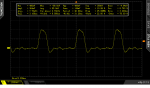
But there are some luck as well. The signal is routed to the TPM port present on the board. So I hooked up the oscilloscope and found out that the signal was indeed not OK. It should be 3.3V but was only about 0.5V.
There are reports that the official fix from many other manufacturers that repair costumer boards with this problem is simply to power bump the signal back to 3.3V.
On this forum there are some excelent threads describing this exact fix on other boards. Big thanks to all of you :)

On my board the signal was ~0.5V and needed to get to 3.3V. A simple voltage devider with 100ohm and 470ohm, gave me close to 3.3V.
The system started right up and works like a charm. I hope that this can help fixing the Asrocks boards as well.
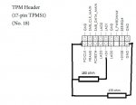
I did like this:
On the TPM connector, described in the manual on page 21 (https://download.asrock.com/Manual/C2750D4I.pdf) i connected two resistors:
- 100 ohm resistor between PCICLK and +3V
- 470 ohm resistor between PCICLK and GND

I don't know if all boards age the same and if the resistor values can be used on any board. So if you try this, it is at your own risk.

/D
 

Attachments

  • TPM.jpg
    TPM.jpg
    43.3 KB · Views: 2,166
  • before.png
    before.png
    17.8 KB · Views: 2,137
Last edited by a moderator:

m3rrym4n

Cadet
Joined
Sep 22, 2015
Messages
1
My ASRock C2750D4I died last year and I've been unable to revive it. This machine was always FREENAS and the firmware is 0.35.00. Symptoms were similar to the OP. I just tried the voltage divider on the TPM header with the exact same resistors suggested and, it WORKED! So far I have a successful post, IPMI is functioning. Now I'm going to put it all back to together and bring this machine back to life. Thanks @online2 !!!
 

brandon099

Cadet
Joined
Apr 5, 2021
Messages
4
Thanks for the write-up! I tried the steps outlined with the resistors, but it still does not POST (but BMC still works). What did you all use to attach the resistors to the pins? I think what I have rigged up for the resistors off of the PCICLK pin isn't quite right or secure enough.
 

online2

Cadet
Joined
Jan 14, 2021
Messages
7
I soldered directly to the pins. Not beautiful bit very functional :)
Just wondering how you know that the BMC is working?
 

brandon099

Cadet
Joined
Apr 5, 2021
Messages
4
Oh okay, what I tried was using some jumper wires and soldered the resistors inline on those wires, so I might try doing it directly as you did :)

The BMC light starts solid when power is first supplied to the board, then after about 30 seconds, it starts blinking as it should. After about a minute or so after, I can log on to the BMC web UI. When trying to power up the rest of the board (from the UI remote control, or from the power button), it stays blank and I get a few "OEM Timestamped" events logged, and that's it. No display or anything else beyond that.
 

brandon099

Cadet
Joined
Apr 5, 2021
Messages
4
Still not working here, unfortunately. Here's a picture of what I ended up changing it to with the direct solder. Still not posting and no video out (I only have 1 stick of RAM in the A1 slot while troubleshooting). So I suppose I will keep troubleshooting things. Where did you trace with the oscilloscope?


IMG_0412.jpg
 

online2

Cadet
Joined
Jan 14, 2021
Messages
7
Maybe your CPU has degraded more or less than mine.
Remove the resistors and measure the voltage between PCICLK and GND when booting. You should have 3.3V@ 25MHz
 

brandon099

Cadet
Joined
Apr 5, 2021
Messages
4
I don't have an oscilloscope that supports 25MHz yet (mine only goes up to 15MHz), but reading it from my multimeter reads around 1.8V between those pins. Does it require I read it at 25MHz, or is that sufficient to know that it is low but not as low as yours?

Thanks for all your suggestions and help! I'm not all too knowledgeable with details like this.
 

Ericloewe

Server Wrangler
Moderator
Joined
Feb 15, 2014
Messages
20,175
If the data is pseudorandom and around ~50% high and ~50% low (generally speaking a desirable characteristic of transmissions), a true RMS measurement would be in the ballpark of 2.3 V for a nominal LPC bus. The first LPC flash IC whose datasheet I found had V_low at 1.1 V, so I could easily imagine your reading being compatible with a slightly-broken LPC bus.
 

RhoTrp

Cadet
Joined
Apr 25, 2021
Messages
2
Well hello there o/

I was gifted a dead Asrock c2750d4i rev 1.02 (with 32GB RAM no less!) and wanted to have a look at it. He was running FreeNAS and was not aware of anything like turning off watchdog.
His story about the board dying: "I rebooted my rig and it wouldn't boot up again, but was working correctly all the time before that"
IPMI worked, last entry something about "CPU overheating", but allas, when I updated the IPMI, the log's where also cleared.

Some searching on the 'Net and I found 2 possible hardware-related errors:
-the NAND flash wearout,
-the TPM clock pulse degredation.

This board might have both?

What I had found thus far, was to solder a 110 Ohm resistor between Pin 1 and Pin 9. but it didn't revive my board.
asrock-c2750d4i pin1-pin9-110ohm.JPG

But here I see a somewhat more elaborate soldering solution.
I'm pretty bad at electronics (more a programmer) so how does this solution differ from Pin1 with Pin9 with an 110 Ohm resistor?

Just wondering how you know that the BMC is working?
That is the NAND flash thingy? https://www.pjrc.com/teensy/W25Q128FV.pdf
Hard to make out... Is it the DIP socketted chip, or the one with the yellow dot close to the RAM?
asrock-c2750d4i winbond.JPG

I have no clue how to check that...
  • Board powers up
  • heartbeat start beating after a a 20 to 30 seconds
  • IPMI works
  • Can't start the rest of the board
  • ?

Well, all help is appreciated:wink:
Let's see how far I can get.

Cheerio,
Rho
 

Ericloewe

Server Wrangler
Moderator
Joined
Feb 15, 2014
Messages
20,175
Well, if IPMI works, the IPMI flash (the soldered one) is likely to be fine. The socketed one is the system firmware (UEFI).

last entry something about "CPU overheating"
I've heard some talk of that being yet another CPU bug, but I don't have any details.
 

RhoTrp

Cadet
Joined
Apr 25, 2021
Messages
2
Well, if IPMI works, the IPMI flash (the soldered one) is likely to be fine. The socketed one is the system firmware (UEFI).
Do you suggest to try the Two-Resistor-Fix from the top of the page from user Online2 (as opposed to my Single-Resistor-Fix), and if that doesn't work, see if I can get y hands on a socketed UEFI flash chip? (preferably some one who knows how to pre-flash it; I have no tools for that)

Since the board was gifted to me, I have no specific interest in having it fixed; It's just that it's kind of a shame to just let it gather dust -if- fixing is feasible with my skillset.

I've heard some talk of that being yet another CPU bug, but I don't have any details.
I have only heard of people seeing that as a one of the last messages in their TPMI logs (same with my logs), but they didn't believe tht was actually the case. Currently, I'll just assume my rig here wasn't thermally damaged. :')
 

online2

Cadet
Joined
Jan 14, 2021
Messages
7
You need the voltage divider as described. A simple resistor won't do the trick.
Does the heart-beat led stop flashing when you try to start the device?

Well hello there o/

I was gifted a dead Asrock c2750d4i rev 1.02 (with 32GB RAM no less!) and wanted to have a look at it. He was running FreeNAS and was not aware of anything like turning off watchdog.
His story about the board dying: "I rebooted my rig and it wouldn't boot up again, but was working correctly all the time before that"
IPMI worked, last entry something about "CPU overheating", but allas, when I updated the IPMI, the log's where also cleared.

Some searching on the 'Net and I found 2 possible hardware-related errors:
-the NAND flash wearout,
-the TPM clock pulse degredation.

This board might have both?

What I had found thus far, was to solder a 110 Ohm resistor between Pin 1 and Pin 9. but it didn't revive my board.
View attachment 46781

But here I see a somewhat more elaborate soldering solution.
I'm pretty bad at electronics (more a programmer) so how does this solution differ from Pin1 with Pin9 with an 110 Ohm resistor?


That is the NAND flash thingy? https://www.pjrc.com/teensy/W25Q128FV.pdf
Hard to make out... Is it the DIP socketted chip, or the one with the yellow dot close to the RAM?
View attachment 46782

I have no clue how to check that...
  • Board powers up
  • heartbeat start beating after a a 20 to 30 seconds
  • IPMI works
  • Can't start the rest of the board
  • ?

Well, all help is appreciated:wink:
Let's see how far I can get.

Cheerio,
Rho
 

JesseTheStig

Cadet
Joined
May 5, 2021
Messages
2
Hey all,

Looking for some insight here. I just picked up a "dead board" ixsystems freenas mini 2.0 off of ebay for a heavily discounted price supposedly with the c2000 bug thinking I could fix it with the trick mentioned in the first post.

When I plug in and power the machine on I get nothing out of the vga, the fans spin up and the status led next to the power and reset pins goes solid green. What I believe is the bmc led, the one closer to the ram to the left of the cmos, is solid when I first plug it in and try to to turn it on but then after 30 seconds it starts blinking.

As mentioned in replies above, I checked the voltage with a multimeter between the PCICLK and GND pins during boot and I'm only seeing 0.10v to 0.15v. With the voltage jumper added, minus the 470 ohm resistor between PCICLK and GND because I was only getting 2.8v with it and still keeping the 100 ohm one between PCICLK and 3v, I'm getting 3.35v across PCICLK and GND.

When plugged into my network, I don't see the IPMI ip popping up which makes me believe that isn't working as well. Also changed out the CMOS with a fresh battery and reseated the RAM just as extra troubleshooting.

Any advice or next troubleshooting steps would be greatly appreciated. Thanks!
Small update after messing around a little more. I was able to get into IPMI after hooking it up to a switch instead of trying to used a bridged connection from my laptop. Also I realized I have a typo above with the resistor I mentioned I'm using between PCICLK and 3v, it is a 1000 ohm resistor not a 100 ohm.
 

Marcy20

Cadet
Joined
Jun 22, 2021
Messages
2
hello i have the same board here with the same problem. if I don't add any resistors, the board starts up 5 times and then it stays on. with the resistors it stays the same but there is no image. reg 1.03 BMC 00.35.00. if necessary someone can help.
 
Top