How to measure the drive spin-up peak current

Status
Not open for further replies.

Bidule0hm

Server Electronics Sorcerer
Joined
Aug 5, 2013
Messages
3,710
Index

It's a post in the PSU sizing sticky that has started the whole thing...

Disclaimer: only you are responsible of what you're doing to your server, incorrect build can lead to fire and/or to the destruction of the drive, MB, PSU, or any other component connected to the same system. These instructions are not for the beginner; use them at your own risks.

 
Last edited:

Bidule0hm

Server Electronics Sorcerer
Joined
Aug 5, 2013
Messages
3,710
The circuit


The goal

It's to measure the value of the current peak during a drive spin-up without expensive tools, like an oscilloscope for example. The budget is set at $15 max.


The circuit diagram

b_w_44d9459f780567814d5605598f9fb418.png


How it works

Important: the circuit needs to be isolated from everything else than the shunt resistor in the server, a plastic case is a good idea. Also, you can't power it from the server PSU, you need an isolated PSU, that's why we use 9 V batteries.

The 3.3 k resistor, diode, the 1 k and 510 Ohms resistors and the LED are here to create two virtual grounds, I'll explain why a little further down.

Rs is the shunt resistor used to measure the current. It's only 20 mOhms to avoid a too large voltage drop (because a drive will not be happy if the 12 V is only 10 V for example).

It is created by soldering a length of wire in series with the 12 V wire of a molex to SATA adapter (yep, you need to cut the yellow wire to solder your shunt, so don't use an adapter you care too much about :))

3d7661961aaaacd8a64902569d1cec89.png


With 24 AWG wire L needs to be equal to 24.4 cm. With 22 AWG wire L needs to be equal to 38.8 cm. If you use another gauge then you can calculate the length L with this calculator (put the wire diameter and adjust the length until your are very close to 20 mOhm).

I recommend to keep the connections between Rs and the circuit relatively short (let's say 20 cm max) and to use a twisted pair because the signal is very small so you want to limit the noise.

Then there's a low-pass filter formed by the 1 k resistor and the 100 nF capacitor to filter any high frequency noise.

After that there's the op-amp configured as a non-inverting amplifier with a gain of 50. Note that there's a 100 nF bypass capacitor who goes between the power pins of the op-amp which is not represented on the diagram. You can omit it but it's not recommended.

Finally there's a diode and a capacitor (it's called a peak detector) to memorize the peak value so you have the time to read it (and a crappy DMM has the time to settle).

The output is 1 V/A so for example if you read 2.61 V then you now it's equal to 2.61 A.

So now, why we need two virtual grounds? well, the diode used in the peak detector isn't perfect so it has a forward voltage. The second virtual ground is used to cancel this voltage.

Ok, but why we need a virtual ground in the first place? because the op-amp isn't perfect too and it can't work with its inputs near the rail voltages (that's why many circuits with op-amp use virtual grounds or split supplies).


The BOM
  • 1x 510 Ohms resistor
  • 4x 1 kOhms resistors
  • 1x 3.3 kOhms resistor
  • 1x 51 kOhms resistor
  • 2x 100 nF film capacitors
  • 1x 100 µF (16 V minimum) electrolytic capacitor
  • 2x 1N4004 diodes
  • 1x 5 mm LED blue or white
  • 1x LM741
  • 1 foot of 24 AWG (or 2 feet of 22 AWG) solid core wire (CAT5(e) cable is very good for this and you've probably already have some on a shelf)
  • 1x molex to SATA adapter
  • 2x 9 V batteries
  • 1x DMM (even a crappy $5 one)
  • Some way to assemble the thing (breadboard, stripeboard, homemade PCB, deadbug circuit, ...)

Miscellaneous

Important: the circuit needs to be isolated from everything else than the shunt resistor in the server, a plastic case is a good idea. Also, you can't power it from the server PSU, you need an isolated PSU, that's why we use 9 V batteries.

If you use 5 % resistors and you are careful in the making of the shunt resistor then the circuit precision will be (better than) 5 %.

Note that you can use two 1 kOhms resistors in parallel instead of the 510 Ohms resistor and three 1 kOhms resistors in series instead of the 3.3 kOhms resistor, that way you just need a batch of 1 kOhms resistors and one 51 kOhms resistor.

Of course you can add a shunt on the +5 V rail if you want to measure the current on this rail.
 
Last edited:

Bidule0hm

Server Electronics Sorcerer
Joined
Aug 5, 2013
Messages
3,710
Reserved.
 

Bidule0hm

Server Electronics Sorcerer
Joined
Aug 5, 2013
Messages
3,710
Other measurement methods with a DMM


Using a shunt resistor

If you have a fast and precise enough DMM with a max hold mode (in others words: not a $5 one) you can use it directly on the shunt resistor without the amplifier + peak detector circuit. However I recommend to put a low-pass filter like this:

74e92cf1694efe8ba19af472adb0c3ad.png


If your DMM is a high count one (40000 or 50000 counts for example) then there's maybe a mode with a reduced resolution (usually 4000 or 5000 counts) but a higher refresh rate --> use it.

If it doesn't have a max hold mode then you can still use it but you'll need to memorize yourself the max value, which can be a bit tricky.

Of course you need to multiply the read value by 50 to have the Amps.


Using a current clamp

You can use a current clamp like this one for example ($50 on ebay), there's a review of it here.

You don't need to cut any wire and you don't need to build anything. However it's more expensive and you need to make sure your current clamp can measure DC currents and that it has a bandwidth of a few kHz minimum.

Of course the same recommendations apply for the DMM as described in the "Using a shunt resistor" section.

NB: Some current clamp have a BNC connector, some have banana jacks, some have both. DMMs use banana jacks so you may need a BNC/banana jacks adapter.
 
Last edited:

Bidule0hm

Server Electronics Sorcerer
Joined
Aug 5, 2013
Messages
3,710
Other measurement methods with an oscilloscope


Using a shunt resistor and a differential probe

You can use the same circuit as in this post to measure the current with an oscilloscope but only if you have a differential probe (because the shunt is on the +12 V rail on a grounded PSU and one side of the oscilloscope's probe is grounded to).

Of course you need a digital oscilloscope or a analog one with a long persistence mode or a standard analog one + a digital camera and you take a long exposure photo of the screen.

You can't use the CH1 - CH2 trick to make a differential probe with two channels and the math function because you can't be AC coupled (the peak is 100s of ms long) and if you DC couple you'll be limited by the resolution of the ADC (and 99% of the oscilloscopes use 8 bits ADC so when you are at 2 V/div the LSB is about 60 mV, at best) so as we use a shunt of 20 mOhms (because you can't use 1 Ohm for example, at 1 A you'll be at 11 V on the drive --> already out of the ATX spec) the resolution will be 3 A and actually there's to much noise to even see a 3 A change... I tested it, it's just impossible to extract something useful with this method, at least on a digital oscilloscope, an analog one has maybe enough range on the vertical position setting to do this but I'd not count on this.


Using a shunt resistor and no differential probe

If you don't have a differential probe you can put the shunt on the ground side BUT you'll measure the sum of the +12 and +5 V currents and more importantly you'll need to float the drive (including unscrewing it and removing the SATA cable) because its ground isn't the same as server ground anymore. And you must plug the probe's ground to the PSU side of the shunt, not the drive side.

That's the method I used to take the captures in this post but I don't recommend it unless you know exactly what you're doing.


Using a current clamp

You can use a current clamp like this one for example ($50 on ebay), there's a review of it here.

You don't need to cut any wire and you don't need to build anything. However it's more expensive and you need to make sure your current clamp can measure DC currents and that it has a bandwidth of a few kHz minimum.

NB: Some current clamp have a BNC connector, some have banana jacks, some have both. Oscilloscopes use BNC connectors so you may need a banana jacks/BNC adapter.
 
Last edited:

Bidule0hm

Server Electronics Sorcerer
Joined
Aug 5, 2013
Messages
3,710
Reserved.
 

Bidule0hm

Server Electronics Sorcerer
Joined
Aug 5, 2013
Messages
3,710
Spin-up current waveforms captures of various drives

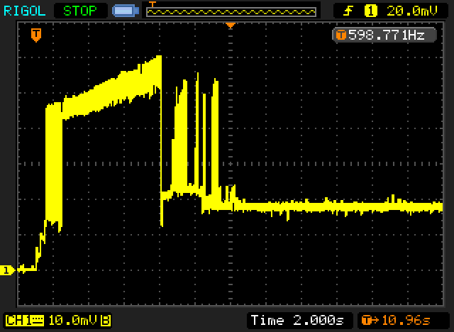
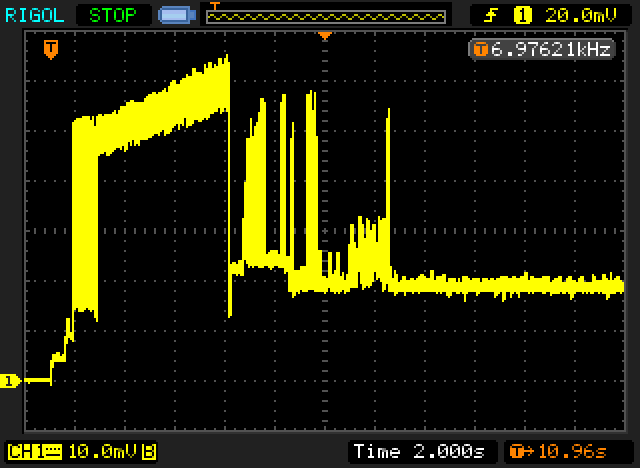
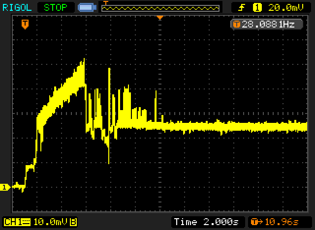
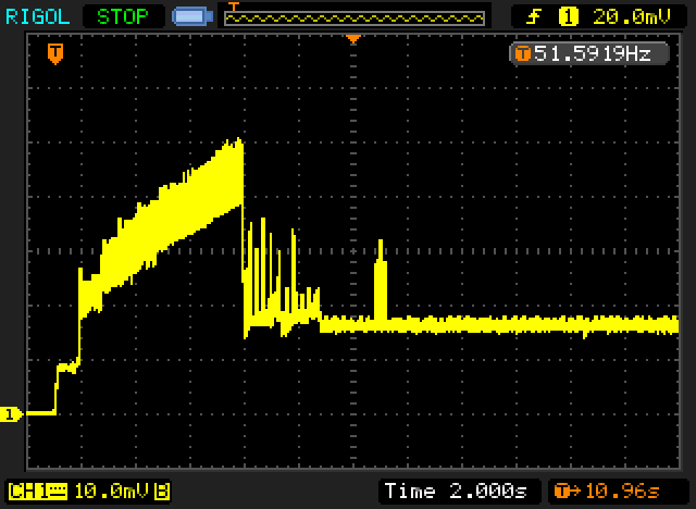
Note that because I don't own a differential probe these captures show the sum of the +12 V and +5 V rails currents.

I used a 20 mV/A shunt so each vertical division is 0.5 A. I used a low-pass filter formed with a 2.2 k resistor and a 100 nF capacitor to reject any high frequency noise.

The trigger point is when I turned on the PSU.

List of the tested drives:
  • Hitachi 1TB [HDS721010DLE630]
  • Samsung SpinPoint F3 1TB [HD103SJ]
  • Seagate NAS 3TB [ST3000VN000]
  • Seagate NAS 4TB [ST4000VN000]
  • Western Digital Caviar Blue 500GB [WD5000AAKS]
  • Western Digital Red 3TB [WD30EFRX]
  • Hitachi 320GB [TS5SAA320] (2.5")

Hitachi 1TB [HDS721010DLE630]

6f69f6f01728f0957ff151a7d6f26b6b.png


Samsung SpinPoint F3 1TB [HD103SJ]

8534b1337bce3f1ea311ea7f36dee808.png


Seagate NAS 3TB [ST3000VN000]

1d1affb9946731cfa7049b9607650179.png


Seagate NAS 4TB [ST4000VN000]

5803873c7afcf2b7fca58b83d0241c0c.png


Western Digital Caviar Blue 500GB [WD5000AAKS]

86dae18efab7893ef4e2ca3fa995509c.png


Western Digital Red 3TB [WD30EFRX]

53551e4c21358c104c79260cf65f7ebb.png


Hitachi 320GB [TS5SAA320] (2.5")

52204069ce7a1eded4e76b0f69323759.png


We can see that with every drive we have the spin-up (the ramp part, some drives uses a double or triple ramp) followed by the heads unparking (one to a few peaks) followed by some seek/reads (the noisy part) to check the drive and to try to find a MBR I guess.

We can see that each drive is waiting about one second after power on before spinning-up.

The 2.5" drive is a little different than the others but it follows the same principles.
 
Last edited:

Bidule0hm

Server Electronics Sorcerer
Joined
Aug 5, 2013
Messages
3,710
Reserved.
 

MindBender

Explorer
Joined
Oct 12, 2015
Messages
67
Note that because I don't own a differential probe these captures show the sum of the +12 V and +5 V rails.
You could use two probes on two channels to have your scope measure the voltage on both ends of the shunt, and have your scope subtract the two. Of course you would need to select proper vertical scale and offset for both channels to get a decent resolution, but it is feasible.

Can you fill us in on the vertical resolution on your oscillographs? They all show both 10mV and 20mV. I'm not familiar with the Rigol screen layout, but can I assume that the 20mV at the top is your trigger level and the 10mV and the bottom is a vertical resolution of 10mV/div? In that case, with a 20mV/A shunt, a worst case current of 1.5A for the top drive isn't that bad imho...
 

Bidule0hm

Server Electronics Sorcerer
Joined
Aug 5, 2013
Messages
3,710
Yeah I know the CH1 - CH2 trick but you can't use it here because you need to be DC coupled and you want to see very small signal on top of very big signal, I explained the problem in more details in this post ;)

Lower left corner is always channel parameters and top of the screen is always the trigger parameters, also I clearly said "[...] each vertical division is 0.5 A." but I know it's easy to miss that kind of info, it happens to me too :) BTW the peak current for the first drive is 3 A, not 1.5 A (6 divs x 0.5 A/div --> 3 A).
 

MindBender

Explorer
Joined
Oct 12, 2015
Messages
67
also I clearly said "[...] each vertical division is 0.5 A." but I know it's easy to miss that kind of info, it happens to me too :) BTW the peak current for the first drive is 3 A, not 1.5 A (6 divs x 0.5 A/div --> 3 A).
I didn't miss it, but I interpreted it as 20 mV/A on 10mV/div, making 6 divs 60mV, uh, yeah, 60mV/20mV*1A = 3A :oops:. The error snuck in using 20mV/0.5A. Yeah, was clearly there. Sorry for the quick miscalculation.
Anyway, 3A is pretty bad! That's 36 Watt!
 

jgreco

Resident Grinch
Joined
May 29, 2011
Messages
18,681
Lower left corner is always channel parameters and top of the screen is always the trigger parameters, also I clearly said "[...] each vertical division is 0.5 A." but I know it's easy to miss that kind of info, it happens to me too :) BTW the peak current for the first drive is 3 A, not 1.5 A (6 divs x 0.5 A/div --> 3 A).

Yeah, I kept looking at that and re-reading it, thinking I was misinterpreting what you meant by "vertical division." Holy amp-suck Batman.
 

Bidule0hm

Server Electronics Sorcerer
Joined
Aug 5, 2013
Messages
3,710
I didn't miss it, but I interpreted it as 20 mV/A on 10mV/div, making 6 divs 60mV, uh, yeah, 60mV/20mV*1A = 3A :oops:. The error snuck in using 20mV/0.5A. Yeah, was clearly there. Sorry for the quick miscalculation.
Anyway, 3A is pretty bad! That's 36 Watt!

Don't worry, it happens :)

Yep, that's why 7200 RPM drives aren't a good idea in a NAS... and it's only a 1 TB one, with a 3 or 4 TB drive the peak should even be higher because there's more platters.

I just received a new drive from RMA, it's a Seagate NAS 4 TB (ST4000VN000) and I think I'll do a current capture before I put it in the server :D

Yeah, I kept looking at that and re-reading it, thinking I was misinterpreting what you meant by "vertical division." Holy amp-suck Batman.

Well, a cup of coffee should take care of that... :P
 

Bidule0hm

Server Electronics Sorcerer
Joined
Aug 5, 2013
Messages
3,710
What? you need a mug? a bowl? a truck?
 

jgreco

Resident Grinch
Joined
May 29, 2011
Messages
18,681
What? you need a mug? a bowl? a truck?

"Yes."

I updated the PSU sizing sticky with a link here and also borrowed one of your images as a sample. It seems obvious that there are some significant differences in the drives and the load they impose, so it seems like a safe bet that you COULD design using certain drives to reduce the likely watt-draw a fair bit, but I think the general guidance for anything less than ten drives still works out very similarly.
 

Bidule0hm

Server Electronics Sorcerer
Joined
Aug 5, 2013
Messages
3,710
Ok, I'll look at the sticky when I'll have finished to do the capture on the new drive, thanks ;)

Yeah, but I don't like coffee :P
 

Bidule0hm

Server Electronics Sorcerer
Joined
Aug 5, 2013
Messages
3,710
Annnddddddddd the winner is...

The Seagate NAS 4TB with a 3.25 A peak and more than 3 A during 2 seconds\0/

I think you can update the capture in the sticky as it's more representative of the kind of drive we use in our NAS.

NB: it's not the 12 V power but the 12 V + 5 V current, I know you like to be picky on these kind of things :)

Edit: didn't think of it at first but now it's confirmed that when the datasheet says 2 A on the 12 V rail it's true (not just a max value not attained IRL) and that it's in addition to the 4.8 W during normal operation.
 
Last edited:
Status
Not open for further replies.
Top