How to build a PCIe bracket for a standard SSD that powers it too

Status
Not open for further replies.

Bidule0hm

Server Electronics Sorcerer
Joined
Aug 5, 2013
Messages
3,710
Index

Disclaimer: only you are responsible of what you're doing to your server, incorrect build can lead to fire and/or to the destruction of the SSD, MB, PSU, or any other component connected to the same system. These instructions are not for the beginner; use them at your own risks.

 
Last edited:

Bidule0hm

Server Electronics Sorcerer
Joined
Aug 5, 2013
Messages
3,710
Reserved.
 

Bidule0hm

Server Electronics Sorcerer
Joined
Aug 5, 2013
Messages
3,710
Introduction


What we want to do is a bracket that will be capable of holding the SSD in a PCIe slot and use the slot +12 V rail to power the SSD.

We will use the male connector of a cheap PCIe riser and some aluminum angle to make the bracket.

The PCIe slot only have a +12 V and a +3.3 V rail but a 2.5" SSD works with 5 V so we will use the good old LM7805 to make a +5 V rail from the +12 V rail of the PCIe slot.
 
Last edited:

Bidule0hm

Server Electronics Sorcerer
Joined
Aug 5, 2013
Messages
3,710
Reserved.
 

Bidule0hm

Server Electronics Sorcerer
Joined
Aug 5, 2013
Messages
3,710
What you'll need


  • 1x SSD
  • 1x SATA cable
  • 1x SATA power cable
  • 1x PCIe riser
  • 1x LM7805
  • 2x 22 to 100 µF (16 V minimum) electrolytic capacitors
  • At least 100 mm of aluminum angle
  • A few small bolts, nuts, washers, ...


SSD and SATA cable

Well, I assume I don't have to give any details on that... :D


SATA power cable

Any reasonable quality SATA power connector with 10-15 cm of cable is perfect. Personally I used a molex to SATA adapter and just cut the molex connector.


PCIe riser

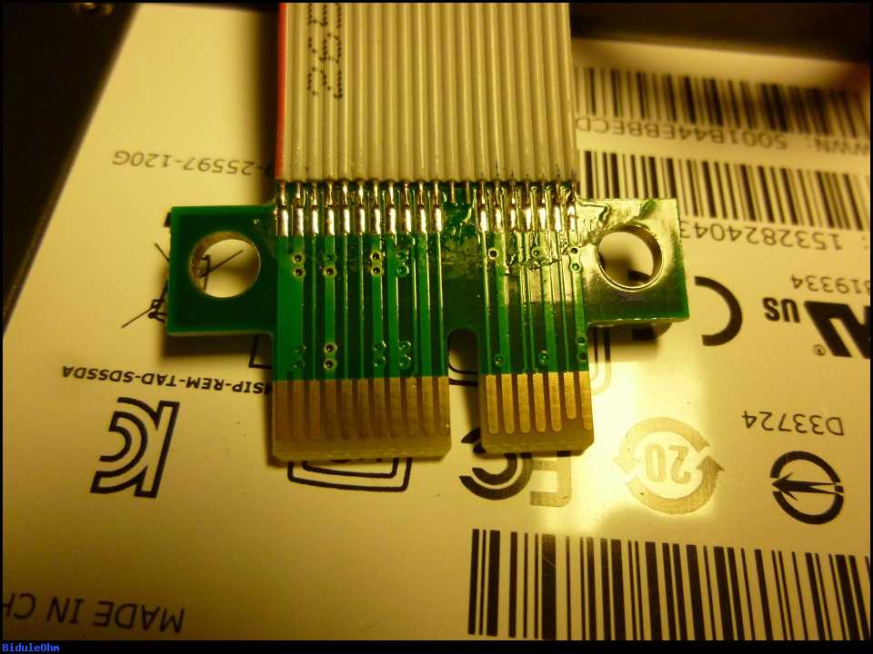
It's probably the most difficult part to find for this project but ebay is magic... What you want is this (it's only the male connector of the riser):

b_w_2f510295b277023c5feafa03e5e957ed.jpeg


It needs to have holes (or you'll have to use some epoxy in place of the bolts...), usually you can see through the tape if there's holes or not in the PCB. For example:

d2b4856dd66cab784b44187e312364c5.jpeg


It can be found for less than 2 dollars. Personally I've chosen this one: http://www.ebay.fr/itm/301747622928?_trksid=p2060353.m2749.l2649&ssPageName=STRK:MEBIDX:IT


LM7805

It's just a 5 V regulator, any electronic supplier will have it.


22 to 100 µF (16 V minimum) electrolytic capacitors

Same as for the 7805: any electronic supplier will have them.


100 mm of aluminum angle

It'll be the main part of the bracket. Personally I've chosen 25*25*2 mm aluminum angle.


So, you should have something like this (yes, I forgot the capacitors and bolts for the picture...):

b_w_db2f6a63af435753ed8f970e852c0107.jpeg
 
Last edited:

Bidule0hm

Server Electronics Sorcerer
Joined
Aug 5, 2013
Messages
3,710
Reserved.
 

Bidule0hm

Server Electronics Sorcerer
Joined
Aug 5, 2013
Messages
3,710
The build


First you'll need to drill all the holes in the aluminum angle: 2 holes for the PCIe connector, one for the LM7805 and 2 for the SSD (plus 2 others if you want to tie-wrap the power cable to the angle for strain relief); of course the holes positions will depend on your particular MB, how you want to put the SSD, etc. Then you'll need to clean the angle (metal filings and delicate electronics don't go well together... :D).

Next you'll need to fasten the PCIe connector (see below for more details) and then the LM7805, don't forget to put some thermal paste between the 7805 and the angle. NB: the angle needs to be aluminum because of his very good thermal conductivity. As you can see I placed the 7805 at the right place so the input pin (see below for the schematic diagram and the PCIe slot pinout) can be directly soldered on the right pads of the PCIe connector:

b_w_a50953ba46eb95c1cd60ef42d51392ae.jpeg


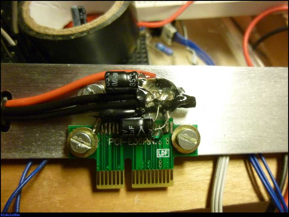
Then solder the capacitors and the wires of the SATA power connector:

b_w_0040379c2540dca589142bd6274a372a.jpeg


Add some heat-shrink tubing for good measure:

b_w_d1f238e40408059e80e19480032a7e89.jpeg


And a bit of hot melt glue just to be sure:

b_w_572de54e9d13af9d866a8173d4647e44.jpeg


Here you can see better how the PCIe connector is fixed to the angle: there's two washers used as spacers and I isolated the connector solder pads from the angle with some electrical tape just to be sure:

b_w_8f6b602b93dcf883585dddb05a46c9a9.jpeg


The schematic diagram:

b_w_3bceadf39fb5f128932ced970022bb11.jpeg


The PCIe slot pinout:
a0e40423406ea0342cedaa239c0e98db.png
 
Last edited:

Bidule0hm

Server Electronics Sorcerer
Joined
Aug 5, 2013
Messages
3,710
Reserved.
 

Bidule0hm

Server Electronics Sorcerer
Joined
Aug 5, 2013
Messages
3,710
A little mistake...


You may have seen that I made a mistake:

b_w_3f02e5a3e708b20251a38f01e2abdd5f.jpeg


That's why you want to double check and triple check an electronic circuit before applying power :)

Of course I fixed it; simply by cutting the trace just right next to the "LDF" text.

There's no problem on the back side as the washer is smaller. On the other side there's also no problem as the leftmost trace is a ground trace.
 
Last edited:

Bidule0hm

Server Electronics Sorcerer
Joined
Aug 5, 2013
Messages
3,710
Reserved.
 

Bidule0hm

Server Electronics Sorcerer
Joined
Aug 5, 2013
Messages
3,710
The result


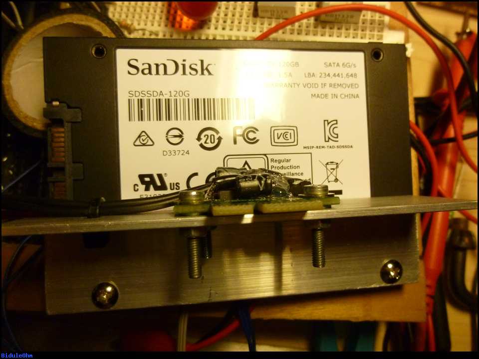
Some pictures of the end result:

b_w_4286bca272d5ca9ff5a8865adf64b6bd.jpeg


b_w_4e9c569277e286c6cc67540e6acbfb3a.jpeg


b_w_29fcc24e3ebc27ccb232ce23610552da.jpeg
 
Last edited:

Bidule0hm

Server Electronics Sorcerer
Joined
Aug 5, 2013
Messages
3,710
Reserved.
 

Bidule0hm

Server Electronics Sorcerer
Joined
Aug 5, 2013
Messages
3,710
Reserved.
 

Chris Moore

Hall of Famer
Joined
May 2, 2015
Messages
10,080
Can you fix the photos for this? They are not showing up for some reason.
 
Joined
Apr 9, 2015
Messages
1,258
Very interesting. Any reason why you didn't just install an insulator layer between the pcb and the angle? Even without a lot of weight it is possible that stress and vibration could cause the pcb to break allowing things to shift. Using a thin piece of rubber or even hot glue on the back side of the PCB would allow a larger surface without a gap to spread the stress out a bit.
 

Bidule0hm

Server Electronics Sorcerer
Joined
Aug 5, 2013
Messages
3,710
@Chris Moore they are showing up perfectly here but I'll try at work tomorrow to be sure ;)

@nightshade00013 There's an insulator (3 layers of electrical tape) plus the PCB is spaced from the angle by washers (you don't want to put pressure on the board and so on the insulator so you don't puncture it and you don't bend the board), it's visible on this picture. Of course it's not supra hypra robust mechanically speaking but it's also because I don't have a standard case so I don't have PCI slot bracket support. In a standard case you can easily change some things (add an old PCI card bracket for example) to be able to screw the thing to the case like any other PCI card and not have to worry about that. This thread is really to share the base idea and to show how I made it but there's literally a ton of things you can change to suit your needs :D
 

gpsguy

Active Member
Joined
Jan 22, 2012
Messages
4,472
Can you fix the photos for this? They are not showing up for some reason.

What browser are you using? Are you running any extensions?

I am in my phone right now, but can see them with Tapatalk.
 

Dice

Wizard
Joined
Dec 11, 2015
Messages
1,410
Pics work fine on Chrome.

cool project.
 

Bidule0hm

Server Electronics Sorcerer
Joined
Aug 5, 2013
Messages
3,710
Yep, I can confirm they works at my work too ;)
 

Chris Moore

Hall of Famer
Joined
May 2, 2015
Messages
10,080
Sorry, It is probably the place I work blocking the site that hosts the images.
 
Status
Not open for further replies.
Top