Help with design plans for rack mounting my stuff

Status
Not open for further replies.

BigDave

FreeNAS Enthusiast
Joined
Oct 6, 2013
Messages
2,479
Out of curiosity, do those carry a warning against mixing and matching them with 3.5" drives? I imagine these might lead to 3.5" being starved from airflow due to insufficient static pressure across them.
I could see your point if you placed SSDs in a mix n match type scenario over the whole front of this type of chassis.
If there is some kind of warning against their use, I never saw it mentioned and have not been able to find one since you asked.
My plan is to have only one such tray so since the SSD and slid-in tray in question needs virtually no air flow,
I could install a baffle of some kind to make the air take the proper way around the 3-1/2in. drives.
Me thinks you think too much:p
 

BigDave

FreeNAS Enthusiast
Joined
Oct 6, 2013
Messages
2,479

Jailer

Not strong, but bad
Joined
Sep 12, 2014
Messages
4,977
Me thinks you think too much
Go punch a hole behind the air filter in the airbox in your vehicle and note how long your air filter lasts before it needs replacing. ;)
 

BigDave

FreeNAS Enthusiast
Joined
Oct 6, 2013
Messages
2,479
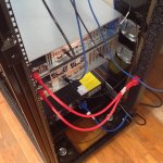
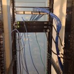
My new chassis project is coming along. I got the HBA hooked to the backplane and
picked up a gaggle of 40GB refurbished ($2.49 ea.) hard drives to test all the bays
and make sure the backplane and HBA were not having any issues.

IMG_1623[1].JPG
IMG_1622[1].JPG

Over the weekend I re-flashed my M1015 card to include the optional boot ROM,
firmware and now can boot from an SSD attached to the backplane using the tray
adapter mentioned in post #18 above.

I do have a mystery yet to solve and I'm hoping someone can shed some light on it.

Shown below is two views of a plug that has some unknown use but I've yet to find
out what it might be.
IMG_1615[1].JPG
IMG_1616[1].JPG

I've looked in detail at the chassis, backplane and the motherboard manuals with no joy.
I'm now going to look at some of the older generation motherboards to try and find a port
or socket that fits this plug. I'd appreciate any assistance or suggestion.
Dave
 

Ericloewe

Server Wrangler
Moderator
Joined
Feb 15, 2014
Messages
20,194
That's a weird connector. It looks like it's for power applications, but one of the conductors has what looks like a ferrite bead, so it would almost certainly be a signal...
 

BigDave

FreeNAS Enthusiast
Joined
Oct 6, 2013
Messages
2,479
That's a weird connector. It looks like it's for power applications, but one of the conductors has what looks like a ferrite bead, so it would almost certainly be a signal...
There's a bead on both the white/yellow and the white/green wires. Because there are two signal wires,
I'm thinking like you that it may have something to do with power monitoring. What is really odd to me
is that as popular as these chassis are, there's not a few google results regarding it's use and purpose.
 

BigDave

FreeNAS Enthusiast
Joined
Oct 6, 2013
Messages
2,479
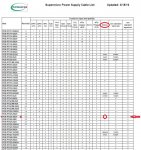
This Supermicro pdf document lists it as an Smbus connector???
cables-list-pdf.JPG
My PDB model# PT825-8824
I also have a PT826-8824 and it also has matching connectors (quantity and type) with the same mystery plug!

Now to find a socket!
 

BigDave

FreeNAS Enthusiast
Joined
Oct 6, 2013
Messages
2,479
This PDF for a BPN-SAS3-217HD-N4 shows a SM Bus Connector, not sure if it helps or not...
This plug could be for a certain type of backplane, I just know the plug doesn't fit either
one of the two BPs I have on hand. Thanks though...
 

Ericloewe

Server Wrangler
Moderator
Joined
Feb 15, 2014
Messages
20,194
SMBus is a more standardized version of I2C, defined for PC peripherals like fan controllers or, what is likely the case here, PSU monitoring.

What doesn't make sense to me is the third wire... I2C is a two-wire interface.
 

BigDave

FreeNAS Enthusiast
Joined
Oct 6, 2013
Messages
2,479
SMBus is a more standardized version of I2C, defined for PC peripherals like fan controllers or, what is likely the case here, PSU monitoring.

What doesn't make sense to me is the third wire... I2C is a two-wire interface.
I'm gonna breakout the multi-tester and find out if the red wire has voltage on it. brb
 

BigDave

FreeNAS Enthusiast
Joined
Oct 6, 2013
Messages
2,479

Ericloewe

Server Wrangler
Moderator
Joined
Feb 15, 2014
Messages
20,194
Seems rather high for an I2C bus...
 

BigDave

FreeNAS Enthusiast
Joined
Oct 6, 2013
Messages
2,479
Just a short update on my build. I purchased two power supplies
for my chassis to replace the 500w redundant units that came with
it. The old units were loud and imho were not going to run 16 hdd.
I got the Supermicro PWS-920P-SQ platinum rated. the noise
level has been reduced by a huge margin, so I very happy with the
upgrade. The new units were unused and cost me $240 shipped.
As they say in the old Master card commercials, "saving your hearing,
priceless"
 

BigDave

FreeNAS Enthusiast
Joined
Oct 6, 2013
Messages
2,479
image.png image.jpeg
for you rack mount geeks out there...

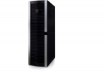
I recently picked up a new rack to replace the Compaq round hole unit that was acquired about 10 months ago. I am now the proud owner of a Dell PowerEdge
4220D!

I also pick up another Supermicro chassis, this time My choice was a 2U 826
12 bay, it will need an upgrade to SQ power supplies and a SAS2 backplane
but I got a really good deal and don't mind the extra cost.

Pictures will be added as new rack goes up this Friday and Saturday.
 

BigDave

FreeNAS Enthusiast
Joined
Oct 6, 2013
Messages
2,479
Just a little update regarding the new rack. I have not had time to take any pictures but things are coming along. I've put in a 24port patch panel and so far have punched down the CAT6 cables for all 12 of the keystone terminals in the house. I was not happy with my firewall having the ethernet ports on the back, so I bought a new 1U case and transfered the existing hardware. Now the I/O is all facing forward and the patch cables are all connected in the front and
now all the twinkely lights make it look like Christmas :cool:

I was in the market for upgrading my UPS from the CP1000PFCLCD to a rack mounted UPS. After much research and online shopping, I stumbled on a pretty good deal on a HPE R/T3000 HV 240v model, brand new open box with all the hardware and cords included. I paid <$180 for it. For an additional $80 in material, I will run a new dedicated 20amp outlet to my computer room to power the new UPS. The advantages of running the higher voltage are more efficient use of electricity and less heat. I am taking measurements of my current equipment and will duplicate this same process once the higher voltage system is operational. I'm excited to see what the results are for an investment of less than $300

Stay tuned all you rack mount geeks;)
 
Last edited:

BigDave

FreeNAS Enthusiast
Joined
Oct 6, 2013
Messages
2,479
Another update on the installation of the new rack mount ups and a power savings (assumed) comparison. I had hoped to do some measured temperature stats, but I've got to help the Better Half get ready for our grandson's b-day party. There's a mention about heat at the end (yes, you have to read it all) :p:p:p

Measured from a single CyberPower CP1000PFCLCD model which is plugged into a 20amp 120v wall outlet.
With all devices at idle, the UPS is showing readings of (output in watts) = 252
-------------------------------------------------------------------------------------------------------------
Equipment Listed Below:
2 - Dell N2024 switches (stacked)
1U pfSense Firewall/Router Server
X9SCM-F | E3-1230 V2 | 16GB RAM | Server
X11SSM-F | Pentium G4400 | 32GB RAM | Server
--------------------------------------------------------------------------------------------------------------
The same equipment as listed above now runs more efficiantly @240v
with a new HPE R /T3000 G4 HV NA/JP UPS Model J2R02A (Rebadged Eaton 5PX3000IRT2U)
plugged into a 20amp 240v (L-6 20R) wall outlet.
With all the devices at idle, the UPS is showing readings of:
output in watts = 216 | output in VA = 359 | 1.5amps | PowerFactor = 0.60
-------------------------------------------------------------------------------------------------------------
It's obvious the Eaton designed UPS is far more superior at monitoring and listing the measurements of power usage for the unit compared to the CyberPower unit. The price difference indicates it should be this way.
I could have been far more detailed in the measurement part of this comparison, but I have to many irons in the fire at this point and can spare no more time for this.
In conclusion, I would also like to point out that all the heat that exits the rear of these machines has been reduced by a noticeable amount. To be blunt, the air coming out now, feels much cooler than it did when everything was running off of 120v power. I am very happy with the less than $320 investment (I also spent some money on fancy power cables), with the power savings AND heat reduction, the hardware purchased will pay for itself in no time.
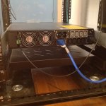
image.jpeg image.jpeg image.jpeg
 
Last edited:

Redcoat

MVP
Joined
Feb 18, 2014
Messages
2,925
I suggest you consider making blank "sidecars" to block the cross-section path alongside the 2.5" drive.
These will do two things: (a) ensure that the gaps do not become a preferential path for air out of the case and thus risk starving existing drives using the same air motive force for cooling and (b) distribute the air available across the 2.5" drives instead of bypassing it in the "alongside" passage.
 
Status
Not open for further replies.
Top