2017 alternative to Lenovo TS140 / Dell T20

Status
Not open for further replies.

bent98

Contributor
Joined
Jul 21, 2017
Messages
171
I am still not following you. I get the fact you can trace the pins from the original io header to the power connector switch. Now you know what pins on the mother board control power. I am not following when you make the transplant. how do you connect the new power switch connector which is a different size to fit into the from the new case to he motherboard male pins on the FPCONN header.
 
Last edited:

lukeren

Explorer
Joined
Apr 13, 2017
Messages
62
You remove this plastic part, so you only have the pins inside of it.
powerswitch.png
 

bent98

Contributor
Joined
Jul 21, 2017
Messages
171
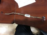
Ok I pulled the cable out and took a picture. Harness Part #(842941-001). The only way I see this working is cutting the end of the power sw plastic housing from the new case shown in your picture and cutting off the proliant switch from the original harness (black and white wires). This way the switch works as intended. I am sorry for sounding dense but I am still not following how you want to wire this up.
 

Attachments

  • IMG_2239.JPG
    IMG_2239.JPG
    216.2 KB · Views: 287

lukeren

Explorer
Joined
Apr 13, 2017
Messages
62
I guess you COULD do that, but then you would probably void your warranty.
The way I've done it, is to remove the plastic housing I showed above, and mounted it like this in the new case:
mobo.jpg
 

bent98

Contributor
Joined
Jul 21, 2017
Messages
171
a picture is worth a thousand words. I see now. how did you get the pins out of the POWER SWITCH plastic housing? I can put some heat shrink around the pins so they dont short.
 
Status
Not open for further replies.
Top