Network
14 minute read.
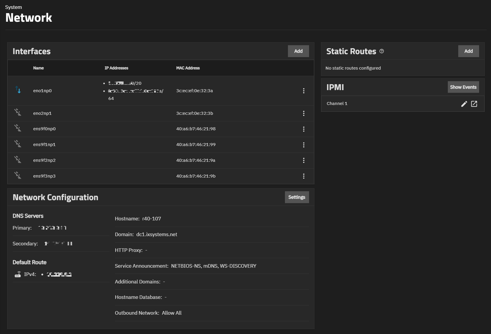
Last Modified 2022-04-07 16:08 EDTThe SCALE Network screen has network configuration and settings options for active interfaces, static routes, and the global configuration.
The Network screen also displays OpenVPN information and IPMI channels.
Each networking configurable is a separate widget on the overview screen. Click the buttons or an existing widget entry to view a side panel with configuration options.
Select a networking section in the box below to see more details about specific configuration options.
The Interfaces section displays network port names and IP addresses, as well as their upload/download rates.
Click on an interface to edit it, click the delete icon next to the interface to delete it, or click Add to add a new one.
Setting | Description |
---|---|
Type | Choose the type of interface. Bridge creates a logical link between multiple networks. Link Aggregation combines multiple network connections into a single interface. A Virtual LAN (VLAN) partitions and isolates a segment of the connection. Read-only when editing an interface. |
Name | Enter a name for the interface. Use the format bondX, vlanX, or brX where X is a number representing a non-parent interface. Read-only when editing an interface. |
Description | Enter a description of the interface. |
DHCP | Select to enable DHCP. Leave checkbox cleared to create a static IPv4 or IPv6 configuration. Only one interface can be configured for DHCP. |
Autoconfigure IPv6 | Set to automatically configure the IPv6 address with rtsol(8). Only one interface can be configured this way. |
Setting | Description |
---|---|
Disable Hardware Offloading | Turn off hardware offloading for network traffic processing. |
MTU | Maximum Transmission Unit, the largest protocol data unit that can be communicated. The largest workable MTU size varies with network interfaces and equipment. 1500 and 9000 are standard Ethernet MTU sizes. Leaving blank restores the field to the default value of 1500. |
Options | Enter additional parameters from ifconfig(8). |
WARNING: Disabling hardware offloading can reduce network performance. We only recommend disabling hardware offloading when the interface is managing jails, plugins, or virtual machines.
The IP Address section lets users define an alias for the interface on the TrueNAS controller. The alias can be an IPv4 or IPv6 address.
Users may also select how many bits are a part of the network address.
The Global Configuration section has all the general TrueNAS networking settings not specific to any interfaces.
Disruptive Change
You can lose your TrueNAS connection if you change the network interface that the web interface uses!
You might need command line knowledge or physical access to the TrueNAS system to fix misconfigured network settings.
Many of these fields have default values, but users can change them to meet local network requirements.
TrueNAS displays the Hostname and Domain in the Dashboard System Information window.
Note: The Global Configuration window only displays some options when the appropriate hardware is present.
Setting | Description |
---|---|
Hostname | System hostname. |
Hostname (TrueNAS Controller 2) | Host name of second TrueNAS controller (for HA only). Upper and lower case alphanumeric, . , and - characters are allowed. |
Hostname (Virtual) | Virtual host name. When using a virtual host, this is also used as the Kerberos principal name. Enter the fully qualified hostname plus the domain name. Upper and lower case alphanumeric, . , and - characters are allowed. |
Domain | System domain name, like example.com |
Additional Domains | Additional domains to search. Separate entries by pressing Enter. Adding search domains can cause slow DNS lookups |
Setting | Description |
---|---|
NetBIOS-NS | Legacy NetBIOS name server. Advertises the SMB service NetBIOS Name. Can be required for legacy SMB1 clients to discover the server. When advertised, the server appears in Network Neighborhood. |
mDNS | Multicast DNS. Uses the system hostname to advertise enabled and running services. For example, this controls if the server appears under Network on MacOS clients. |
WS-Discovery | Uses the SMB Service NetBIOS name to advertise the server to WS-Discovery clients. This causes the computer to appear in the Network Neighborhood of modern Windows OSes. |
Setting | Description |
---|---|
Nameserver 1 | Primary DNS server. |
Nameserver 2 | Secondary DNS server. |
Nameserver 3 | Third DNS server. |
Setting | Description |
---|---|
IPv4 Default Gateway | Enter an IPv4 address. This overrides the default gateway provided by DHCP. |
IPv6 Default Gateway | Enter an IPv6 address. This overrides the default gateway provided by DHCP. |
Setting | Description |
---|---|
Allow All | Any system service can communicate externally. |
Deny All | This system cannot communicate externally. |
Allow Specific | Define the system services that are allowed to communicate externally. All other external traffic is restricted. |
Setting | Description |
---|---|
HTTP Proxy | When using a proxy, enter the proxy information for the network in the format http://my.proxy.server:3128 or http://user:password@my.proxy.server:3128 . |
Enable Netwait Feature | Delays the start of network services until pings return from the IP addresses added to the Netwait IP List. |
Netwait IP List | Only appears when Enable Netwait Feature checkbox is selected. Enter a list of IP addresses to ping. Separate entries by pressing Enter. Each address is tried until one is successful or the list is exhausted. Leave empty to use the default gateway. |
Host Name Database | Additional hosts to append to /etc/hosts. Separate entries by pressing. Separate entries by pressing Enter. Use the format IP_address space hostname where multiple hostnames can be used if separated by a space. Hosts defined here are still accessible by name even when DNS is not available. See hosts for additional information. |
TrueNAS administrators can use the Static Routes section to manually enter routes so the router can send packets to a destination network.
TrueNAS does not have defined static routes by default. If you need a static route to reach portions of the network, add the route by going to Network and clicking Add in the Static Routes window.
Setting | Description |
---|---|
Destination | Use the format A.B.C.D/E where E is the CIDR mask. |
Gateway | Enter the IP address of the gateway. |
Description | Notes or identifiers describing the route. |
A virtual private network (VPN) is an extension of a private network over public resources. VPNs allow clients to securely connect to a private network even when remotely using a public network.
TrueNAS provides OpenVPN as a system-level service for VPN server or client functionality. TrueNAS can act as a primary VPN server that gives remote clients access to data stored on the system using a single TCP or UDP port. Alternately, TrueNAS can integrate into a private network, even when the system is in a separate physical location or only has access to publicly visible networks.
Before configuring TrueNAS as either an OpenVPN server or client, you need an existing public key infrastructure (PKI) with Certificates and Certificate Authorities created in or imported to TrueNAS.
To configure OpenVPN (server or client) on TrueNAS, select the networking credentials, set the connection details, and choose additional security or protocol options.
Go to Network and click Client in the OpenVPN window to configure the OpenVPN client.
Setting | Description |
---|---|
Client Certificate | Choose a valid client certificate that exists on this system and is not revoked. Find more about generating certificates and CAs for OpenVPN here. |
Root CA | Choose the root Certificate Authority that you used to sign the client and server certificates. Find more about generating certificates and CAs for OpenVPN here. |
Remote | A valid IP address or domain name to which OpenVPN connects. |
Port | Enter a port number to use for the connection. |
Authentication Algorithm | Choose an algorithm to authenticate packets. |
Cipher | Choose a cipher algorithm to encrypt data channel packets. |
Compression | Choose a compression algorithm. |
Protocol | Choose the protocol to use when connecting with the remote system. |
Device Type | Choose a virtual network interface. More information is found here. |
Nobind | Enable to prevent binding to local address and port. Must be enabled if OpenVPN client and server are to run concurrently. |
TLS Crypt Auth Enabled | Enable/disable TLS Web Client Authentication. |
Additional Parameters | Additional parameters. |
TLS Crypt Auth | Provide static key for authentication/encryption of all control channel packets when tls_crypt_auth_enabled is enabled. |
Go to Network and click Server in the OpenVPN window to configure the OpenVPN server.
Setting | Description |
---|---|
Server Certificate | Choose a valid client certificate which exists on this system and is not revoked. Find more about generating certificates and CAs for OpenVPN here. |
Root CA | Choose the root Certificate Authority that you used to sign the client and server certificates. Find more about generating certificates and CAs for OpenVPN here. |
Server | Enter the IP address and netmask of the server. |
Port | Enter a port number to use for the connection. |
Authentication Algorithm | Choose an algorithm to authenticate packets. |
Cipher | Choose a cipher algorithm to encrypt data channel packets. |
Compression | Choose a compression algorithm. |
Protocol | Choose the protocol to use when connecting with the remote system. |
Device Type | Choose a virtual network interface. More information is found here. |
Topology | Configure virtual addressing topology when running in TUN mode. (TAP mode always uses a SUBNET topology.) |
TLS Crypt Auth Enabled | Enable/disable TLS Web Client Authentication. |
Additional Parameters | Additional parameters. |
TLS Crypt Auth | Provide static key for authentication/encryption of all control channel packets when tls_crypt_auth_enabled is enabled. |
If you choose the TUN as the Device Type, you can select a virtual addressing Topology for the server:
- NET30: Use one /30 subnet per client in a point-to-point topology. Designed for use when connecting clients are Windows systems.
- P2P: Point-to-point topology that points the local server and remote client endpoints to each other. P2P gives each client one IP address. We only recommend P2P when none of the clients are Windows systems.
- SUBNET: the interface uses an IP address and subnet. SUBNET gives each client one IP address. Windows clients require the TAP-Win32 driver version 8.2 or newer. TAP devices always use the SUBNET for Topology.
TrueNAS automatically applies the Topology selection to any connected clients.
When users enable TLS Crypt Auth Enabled, TrueNAS generates a static key for the TLS Crypt Auth field after saving the options. To change this key, click Renew Static Key. Clients connecting to the server require the static key. TrueNAS stores the keys in the system database and automatically includes them in a generated client config file. We always recommend users back up keys in a secure location.
After configuring and saving your OpenVPN server, generate client configuration files to importing to OpenVPN client systems connecting to the server. You need the certificate from the client system already imported onto the system. To generate the configuration file, click Download Client Config and select the Client Certificate.
Many of the fields for configuring an OpenVPN server or client are identical.
The Additional Parameters field manually sets any of the core OpenVPN config file options. See the OpenVPN Reference Manual for option descriptions.
- Root CA: The Certificate Authority (CA) must be the root CA TrueNAS used to sign the client and server certificates.
- Port: This is the port that the OpenVPN connection uses.
- Compression: Choose a compression algorithm for traffic. Leave the field empty for data to be sent uncompressed. LZO is a standard compression algorithm that is backward-compatible with previous (pre-2.4) versions of OpenVPN. LZ4 is a newer option that is typically faster with fewer system resources required.
- Protocol: Choose between UDP or TCP protocols for OpenVPN.
UDP sends packets in a continuous stream while TCP sends packets sequentially.
UDP is generally faster and less strict about dropped packets than TCP.
To force the connection to be IPv4 or IPv6, choose one of the
4
or6
UDP or TCP options. - Device Type: use a TUN or TAP virtual networking device and layer with OpenVPN. The device type must be identical between the OpenVPN server and any clients.
Because using a VPN involves connecting to a private network while still sending data over less secure public resources, OpenVPN includes several security options. While not required, these security options help protect the data TrueNAS sends into or out of the private network.
- Authentication Algorithm: Validates packets that TrueNAS sends over the network connection. Your network environment might require a specific algorithm. If not, SHA1 HMAC is a good standard algorithm to use.
- Cipher: Encrypts data packets sent through the connection. While not required, choosing a cipher can increase connection security. You might need to verify which ciphers your networking environment requires. If there are no specific cipher requirements, AES-256-GCM is a good default choice.
- TLS Encryption: When TLS Crypt Auth Enabled is selected, TrueNAS encrypts all TLS handshake messages to add another layer of security. TLS Encryption requires a static key that the OpenVPN server and clients share.
When finished configuring the server or client service, click Save. Start the service by clicking the play button next to it in the OpenVPN window.
You may also start the service by going to System Settings > Services and clicking the State toggle. Setting Start Automatically starts the service when TrueNAS completes booting and runs the network and data pools.
IPMI (Intelligent Platform Management Interface) requires compatible hardware! Refer to your hardware documentation to determine if the TrueNAS web interface has IPMI options.
Many TrueNAS Storage Arrays have a built-in out-of-band management port that provides side-band management should the system become unavailable through the web interface.
IPMI allows users to check the log, access the BIOS setup, and boot the system without physical access. IPMI also enables users to remotely access the system to assist with configuration or troubleshooting issues.
Some IPMI implementations require updates to work with newer versions of Java. See here for more information.
IPMI is configured in Network > IPMI. The IPMI configuration screen provides a shortcut to the most basic IPMI configuration.
The IPMI window displays the available IPMI channels. The Identify Light button (flashlight) lets users select a duration for the system’s IPMI to flash so they can identify it. The Manage button (square with an outward-pointing arrow) opens the IPMI manager in a new browser tab.
Click the channel you wish to edit to open the configuration form.
Setting | Description |
---|---|
DHCP | Use DHCP. Clear checkbox to manually configure a static IPv4 connection. |
IPv4 Address | Static IPv4 address of the IPMI web interface. |
IPv4 Netmask | Subnet mask of the IPv4 address. |
IPv4 Default Gateway | Enter the default gateway of the IPv4 connection. |
VLAN ID | Enter the VLAN identifier if the IPMI out-of-band management interface is not on the same VLAN as management networking. |
Password | Enter the password used to connect to the IPMI interface from a web browser. The maximum length accepted in the UI is 20 characters, but different hardware might require shorter passwords. |
Identify Light | Lets users select a duration for the system’s IPMI light to flash on the compatible connected hardware. |
Manage | Opens the IPMI manager in a new browser tab. |
After saving the configuration, users can access the IPMI interface using a web browser and the IP address specified in Network > IPMI. The management interface prompts for login credentials. Refer to your IPMI device documentation to learn the default administrator account credentials.
After logging in to the management interface, users can change the default administrative user name and create additional IPMI users. IPMI utility appearance and available functions vary by hardware.