




TrueNAS Development Documentation
This content follows experimental development changes in TrueNAS 28, a future version of TrueNAS.
Use the Product and Version selectors above to view content specific to a stable software release.
Containers Screens
16 minute read.
The Containers screen allows users to add, edit, or manage Linux containers. It shows No Containers before adding the first container, and then shows the container as stopped.
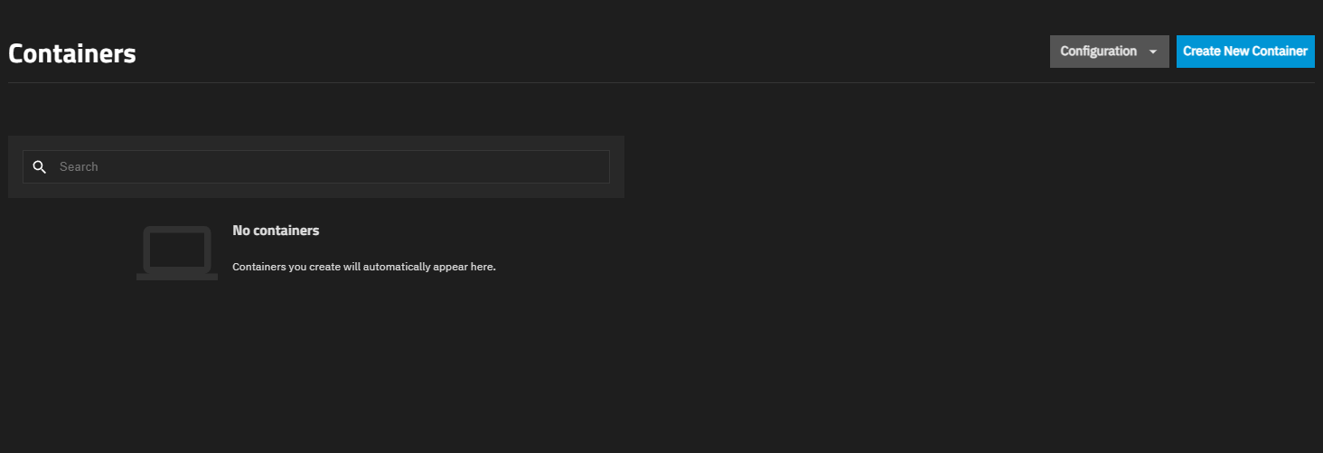
After adding a container, the screen shows a table with rows for each container added in TrueNAS.
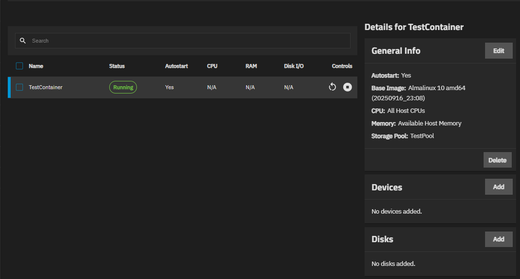
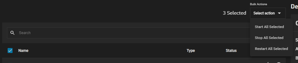
Selecting a container row shows the individual container information cards for the selected row. Selecting the checkbox to the left of any table row shows the bulk operations available to the selected rows.
The screen header shows two options:
Configuration - Shows a dropdown menu with two options:
Settings - Opens the container global settings screen to configure the preferred pool and default network.
Map User/Group IDs - Opens the Map User and Group IDs screen to configure UID and GID mappings.
Create New Container - Opens the Add Container screen.
The Settings screen configures global options that apply to all containers, including an optional preferred storage pool and default network settings.
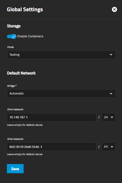
Preferred Pool specifies an optional default storage pool for container data. When a preferred pool is not configured, TrueNAS prompts for pool selection at container creation.
TrueNAS (27 and later) stores containers in a hidden
Images are stored in
The dataset is created per pool. The pool used is set by the Preferred Pool setting or chosen when you create the container.
TrueNAS 25.10 stored containers in.ix-virt . See Migrating Containers from TrueNAS 25.10 in the TrueNAS 27 documentation for information on how TrueNAS migrates them.
Default Network settings configure global networking defaults for the containers service.
| Setting | Description |
|---|---|
| Bridge | Network bridge for containers. Automatic creates and manages a dedicated virtual bridge (truenasbr0) on the TrueNAS host, assigns container IP addresses via DHCP, and routes outbound traffic through the host via NAT. Default ranges are 172.200.0.0/24 (IPv4) and fd42:4c58:43ae::/64 (IPv6), configurable via IPv4 Network and IPv6 Network. Additional options show existing configured bridges. See Accessing NAS from VMs and Containers for more information. Custom bridge selection is not available on High Availability systems. HA deployments always use Automatic to prevent bridge STP issues that could interfere with controller failover. |
| IPv4 Network | (Displayed only when Bridge is set to Automatic) IPv4 address and subnet for the automatic bridge (for example, 192.168.1.0/24). Defaults to the system-assigned address when empty. At least one network (IPv4 or IPv6) must be configured. |
| IPv6 Network | (Displayed only when Bridge is set to Automatic) IPv6 address and subnet for the automatic bridge (for example, fd42:96dd:aef2:483c::1/64). Defaults to the system-assigned address when empty. At least one network (IPv4 or IPv6) must be configured. |
The Map User and Group IDs screen allows manually configuring UID and GID mappings between the TrueNAS host and containers. Map User/Group IDs in the Configuration dropdown on the Containers screen header opens the Map User and Group IDs window.
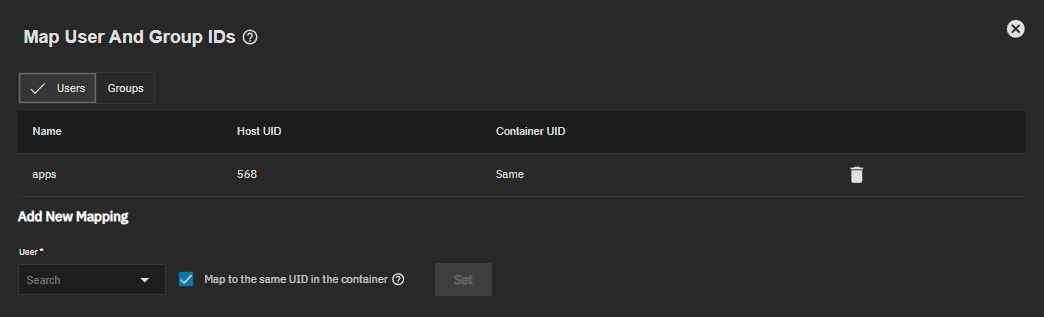
The window opens with the Users tab selected by default. The Groups tab switches to group configuration settings.
Existing mappings appear in a table listing the user or group name, host ID, and container ID. delete Delete on a row removes that mapping.
Set creates the mapping. Changes apply immediately, though restarting the container might be required before they take effect.
The Containers table lists each configured container name, current state, autostart setting, and live resource metrics: CPU %, Memory MiB, and Disk I/O % Full Pressure (shown as N/A when the container is stopped or metrics are unavailable). Each container row includes two buttons:
- restart_alt Restart - Stops, then automatically restarts the container. Does not show when the container is stopped.
- Controls - Starts or stops the container. It toggles between play_circle start or stop_circle stop based on the current state of the container. When stopping a running container, it opens the Stop Options dialog.
Selecting a container row in the table shows the Details for Container cards, which show information and management options for the selected container.
The checkbox at the left of each container row shows the Bulk Actions options.
Search above the Containers table allows entering the name of a container to locate a configured container.
The Stop Options dialog sets how the container stops.
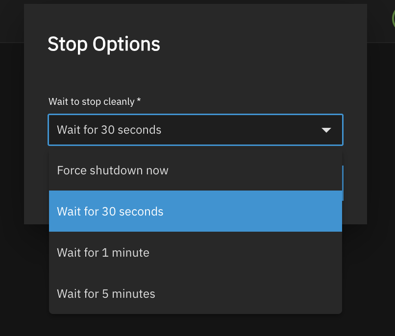
The Stop Method dropdown shows three options:
- Wait for graceful stop - Sends a shutdown signal and waits up to the shutdown timeout for the container to stop gracefully. Does not force-kill the container, so it keeps running if it has not stopped by then.
- Wait for graceful stop, then force - Sends a shutdown signal and waits for the shutdown timeout (default 30 seconds) for the container. Force-kills the container if still running after the timeout expires.
- Force stop immediately - Immediately force-kills the container without attempting graceful shutdown.
The Bulk Actions dropdown list applies the selected action to the containers selected in the table. Options are Start All Selected, Stop All Selected, and Restart All Selected.
The Details for Container cards show information and configuration options for the selected container.
The General Info card shows container configuration details including Description, Autostart, Dataset, CPU Set, Container Time, Shutdown Timeout, Init Process command, and Capabilities Policy. The Init Working Directory, Init User, and Init Group also show when configured.
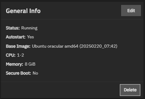
Delete opens the Delete Container dialog.
Edit opens an Edit Container: Container configuration screen populated with editable settings also found on the install wizard screen for the container.
The Delete Container dialog asks for confirmation to delete the selected container and shows three options:
- Stop container before deleting force-stops the container (no graceful shutdown) before deleting it. Required, and selected automatically, when the container is running or suspended.
- Delete child datasets, snapshots and clones also destroys the child datasets and snapshots of the container dataset, and any clones of those snapshots anywhere in the pool, and any snapshot holds, which can break a replication task. Required when the container dataset has child datasets or snapshots. This cannot be undone.
- Confirm activates the Delete button.
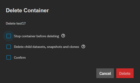
Delete starts the delete operation.
The USB Devices card shows USB devices attached to the container, allowing hardware passthrough for USB peripherals.
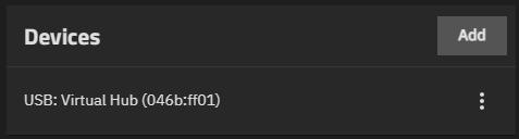
Add shows a list of available USB devices that can be attached to the container.
USB devices appear in the list only if they are physically connected to the TrueNAS system, are not USB hubs, and provide the required information to TrueNAS (bus, device number, vendor ID, and product ID).
The GPU Devices card shows GPU hardware attached to the container for graphics or computation acceleration. TrueNAS allows configuring the same GPU for a VM or a Container, but not both. If your system is equipped with multiple GPUs, TrueNAS allows configuring one for VMs and the other for a container.
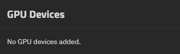
No GPU Devices available shows if TrueNAS does not detect available GPU devices in the system.
Add opens a list of available GPU devices. GPU devices only show in the list if:
- The physical GPU hardware is installed and detected by TrueNAS
- The NVIDIA GPU drivers are installed via System > Advanced Settings
- The GPU device is not currently allocated to another container or VM
HA systems do not support GPU devices.
The Filesystem Devices card shows file system mounts that provide the container with access to host directories and datasets.
File system devices allow containers to read and write data to TrueNAS datasets or host paths.
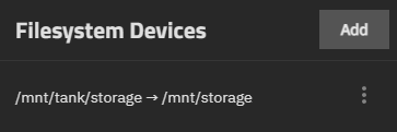
Add activates after stopping the container. It then opens the Add Filesystem Device screen with fields to configure a new file system device mount.
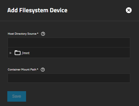
| Setting | Description |
|---|---|
| Host Directory Source | Specifies the host source path for the file system to mount into the container. |
| Container Mount Path | Specifies the mount path inside the container where the file system appears, for example /mnt/data or /var/lib/data. |
For existing filesystem devices, the actions menu includes options to Edit or Delete the filesystem device. Edit opens the Edit Filesystem Device screen. Delete opens the Delete Item dialog.
See Configuring Filesystem Devices in the Containers tutorial for configuration procedures.
The Delete option for a file system opens the Delete Item dialog and removes only the selected file system.
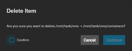
Confirm activates the Continue button. Continue starts the delete process.
The NIC Devices card shows network interfaces (NICs) attached to the container.
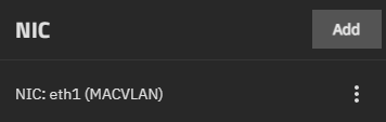
Each NIC device shows the network interface name and MAC address in the format: {interface_name} ({mac_address}). For example: br0 (aa:bb:cc:dd:ee:ff) or br0 (Default Mac Address).
NIC modifications are restricted when there are pending network interface changes on the TrueNAS system. If the card displays a warning about pending changes, apply or revert those network changes before modifying container NICs.
Add shows a list of available network interfaces grouped by type as BRIDGED NICS or MACVLAN NICS. Selecting an interface opens the Add NIC Device dialog.
The Add NIC Device and Edit NIC Device dialogs configure network interface settings for the container.
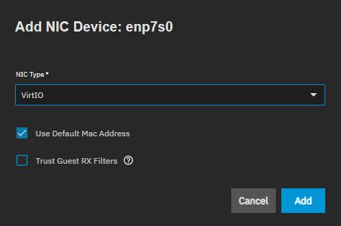
| Setting | Description |
|---|---|
| NIC Type | Sets the NIC type. Options are VirtIO or Intel e82585 (e1000). |
| Use Default Mac Address | Sets TrueNAS to automatically assign a MAC address. Only available when adding a new NIC. |
| Mac Address | Specifies a custom MAC address. Only shows while adding and when Use Default Mac Address is not selected. If editing a NIC, leave empty to use the default MAC address. |
| Trust Guest RX Filters | Sets whether to trust guest OS receive filter settings for better performance. Shows when NIC Type is set to VirtIO. Applies only to a VirtIO NIC added from MACVLAN NICS. For a NIC from BRIDGED NICS, TrueNAS rejects or ignores it. |
Add or Update applies the NIC configuration.
For existing NICs, the actions menu provides options to Edit or Delete the NIC.
NICs can only be modified when the container is stopped.
The Tools card provides quick access to the container shell.
Shell opens a Container Shell session for command-line interaction with the container. The shell is only available when the container is running.
Accessing a web shell requires the Web Shell Access privilege. Shells for apps, containers, and VMs also require the write role for that resource type. The Full Admin role includes all these write roles.
| Shell | Required Privilege and Role |
|---|---|
| System > Shell (host system) | Web Shell Access privilege only |
| VM Serial Shell | Web Shell Access privilege plus the VM write role (VM_WRITE) |
| Container Shell | Web Shell Access privilege plus the container write role (CONTAINER_WRITE) |
| Container Shell (Apps) | Web Shell Access privilege plus the apps write role (APPS_WRITE) |
When authorized, shell commands run as the root user.
The Add Container screen displays basic configuration fields and an Advanced Options button for additional settings.
The basic settings are always visible and configure essential container properties.
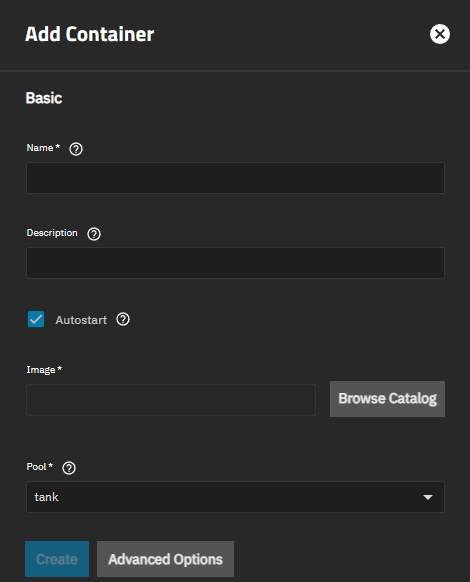
| Setting | Description |
|---|---|
| Name | Specifies a required name for the container. Names consist of upper or lower case alphanumeric or allowed special characters. |
| Description | Specifies an optional description about the container or how it is used. |
| Autostart | Sets the container to automatically start when the system boots. |
| Image | Specifies the operating system image file for the container. |
| Pool | Specifies a storage pool for the container. Only shows when a preferred pool is not configured in Settings. |
| Connect to network | Adds a NIC attached to the bridge set in Bridge on the Settings screen (truenasbr0 when Bridge is set to Automatic). Selected by default. Leave disabled to create the container without network access. Only shows when adding a container. Note: NICs can be added or removed later on the NIC Devices card. |
Browse Catalog opens the Select Image window showing available Linux image choices, and options to search or browse to locate a desired image.
Advanced Options shows the basic and additional configuration settings.
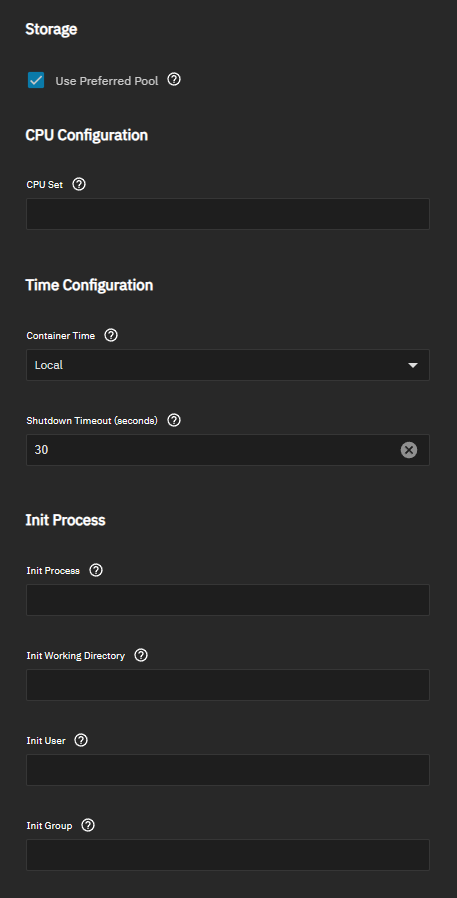
The Storage settings only show when a preferred pool is configured in Settings.
| Setting | Description |
|---|---|
| Use Preferred Pool | Sets the selected pool as the preferred pool to store the container. Only shows when a preferred pool is configured. When selected, this container is stored on the configured preferred pool. When not enabled, the Pool dropdown shows a list of pools to choose from. |
| Pool | Sets a storage pool for the container to use. Only shows when Use Preferred Pool is deselected. |
The CPU Configuration settings bind the container to specific CPU cores.
| Setting | Description |
|---|---|
| CPU Set | Specifies CPU core numbers to allocate to the container (e.g., 0,1,2 or 0-3). Leave blank to allow the container access to all host CPU cores. |
The Time Configuration settings control container time zone and shutdown behavior.
| Setting | Description |
|---|---|
| Container Time | Sets the time zone for the container. Local uses the host system time. UTC uses Coordinated Universal Time. |
| Shutdown Timeout | Specifies the number of seconds to wait for the container to shut down gracefully before forcing termination. Default is 30 seconds. |
The Init Process settings configure the initialization process for the container.
| Setting | Description |
|---|---|
| Init Process | Specifies the init process command line. Default is /sbin/init. |
| Init Working Directory | Specifies the working directory for the init process. |
| Init User | Specifies the user to run the init process as. |
| Init Group | Specifies the group to run the init process as. |
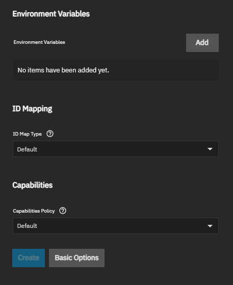
The Environment Variables settings configure optional environment variables to run on boot or execute.
Add shows a set of environment variable Name and Value fields each time it is clicked.
| Setting | Description |
|---|---|
| Name | Specifies the environment variable name (e.g., PATH, HOME). |
| Value | Specifies the value for the environment variable. |
The USB Devices settings configure USB devices for the container. USB device settings only show when creating a container, and only if the system reports an eligible device. Hubs and devices missing identification are left out. At least one USB device must be detectable, or the USB Devices settings do not show in the advanced settings.
USB devices found show as a selectable checkbox option. For example, Virtual Keyboard and Mouse by American Megatrends, Inc.
USB devices pass through to the container. Devices are identified by the physical port they are plugged into.
HA-capable systems cannot use USB passthrough.
Each USB device can only be attached once per container.
The ID Mapping settings configure how user and group IDs (UIDs/GIDs) inside the container map to UIDs/GIDs on the TrueNAS host. This setting is available at container creation only and cannot be changed after the container is created.
| Setting | Description |
|---|---|
| ID Map Type | Sets the UID/GID mapping mode for the container from the options:
|
Setting ID Map Type to Privileged removes all UID isolation between the container and the TrueNAS host. Container processes running as root have direct host root access. Use only when an application explicitly requires it, and you understand the security implications.
Capabilities settings control Linux capabilities, which are special permissions that divide root privileges into distinct units.
Allows containers to perform specific privileged operations without granting full root access.
| Setting | Description |
|---|---|
| Capabilities Policy | Sets the default policy for container capabilities:
|
Device configuration (network interfaces, GPU devices, and file system mounts) is performed after container creation using the detail cards on the Containers screen. You can select USB devices in the advanced settings when you create the container, or add them afterward using the USB Devices card. See Containers Cards for information on configuring devices.
The Edit Container: Container screen includes most settings from the Add Container Screen except Image, Pool, USB Devices, and ID Map Type.
Settings available in edit mode include Name, Description, Autostart, and these Advanced Options: CPU Configuration, Time Configuration, Init Process, Environment Variables, and Capabilities.
Note that the Init Process command field cannot be changed after creation, but Init Working Directory, Init User, and Init Group remain editable.
Device, disk, network, and other settings are configured via the Containers Cards on the Containers screen.
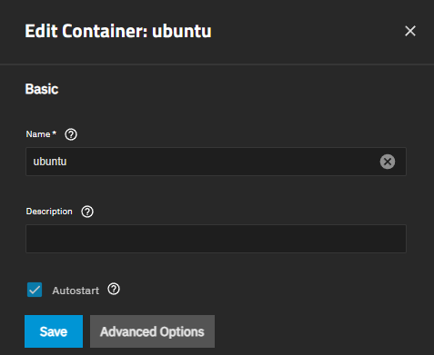
The screen has Basic settings (Name, Description, Autostart) visible by default. Advanced Options expands to show additional configuration sections.
For detailed field descriptions, see the Add Container Screen section. The edit screen uses the same fields except Image, Pool, USB Devices, ID Map Type, and the Init Process command (none of which can be changed after creation).
Autostart in HA Environments
In High Availability configurations, containers with autostart enabled automatically restart on the new active controller after a failover. Ensure containers have static IP addresses configured to maintain network connectivity after failover. See Containers in High Availability Environments for details.