Archival documentation for the TrueNAS SCALE 24.10 (Electric Eel) major version. This documentation is End of Life (EOL) and presented for reference only.
24.10 Electric Eel (Archived)
TrueNAS released 24.10 (Electric Eel) on December 17, 2024. This version received its final update on August 7, 2025. The terminal version of Electric Eel is 24.10.2.4.
TrueNAS employees maintain documentation and provide regular updates for current and in development (future) versions of TrueNAS software.
For documentation purposes, current and future releases are those recommended by the TrueNAS Software Status page for one or more user type.
Documentation for previous releases, that are no longer recommended for any user type, is archived and unmaintained.
All documentation provided here is end-of-life (EOL), intended for reference only, and no longer receives any updates.
24.10 (Electric Eel) brought many new features and improvements to the TrueNAS experience:
The TrueNAS Apps feature backend moves from Kubernetes to Docker to streamline App deployment and management (announcement). Custom App deployment of Docker images is available via a guided wizard or a Compose YAML file.
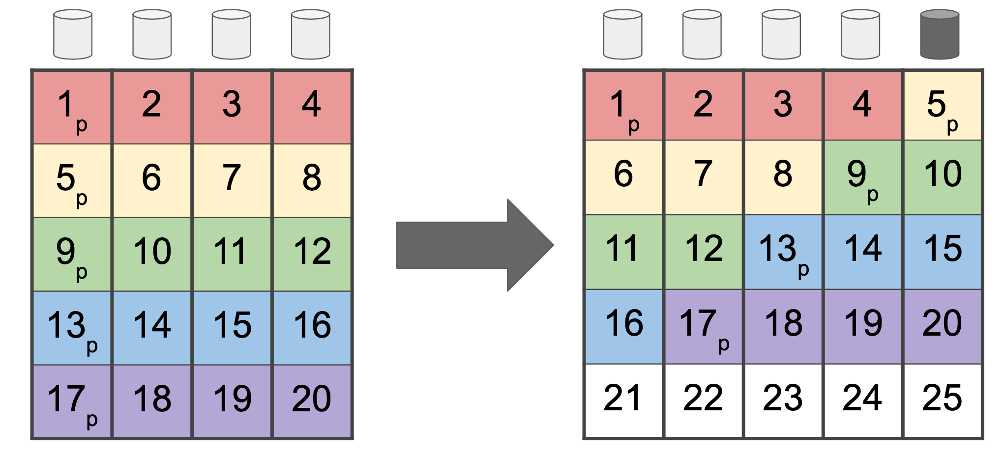
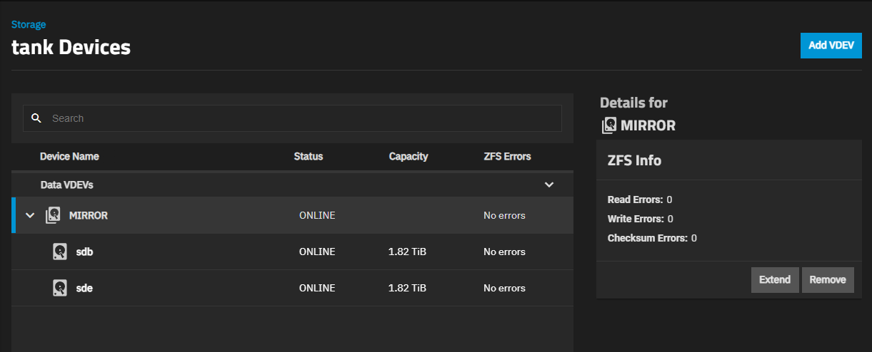
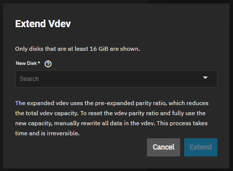
Extend a RAIDZ vdev with individual disks (OpenZFS feature sponsored by iXsystems).
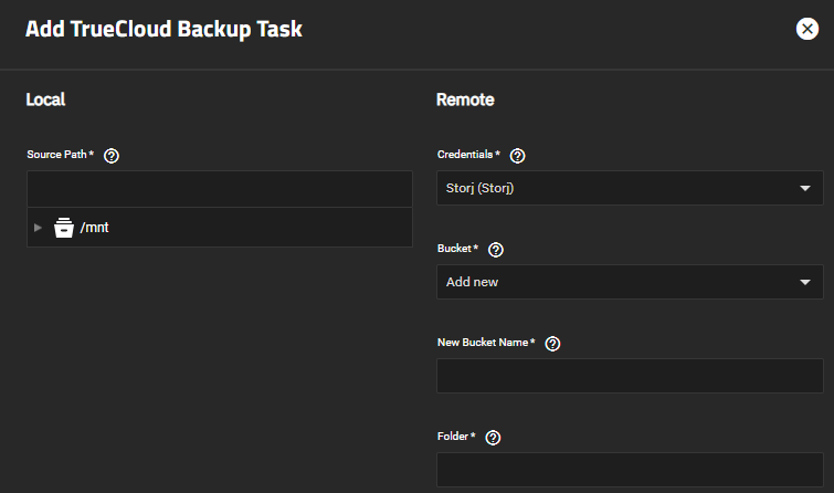
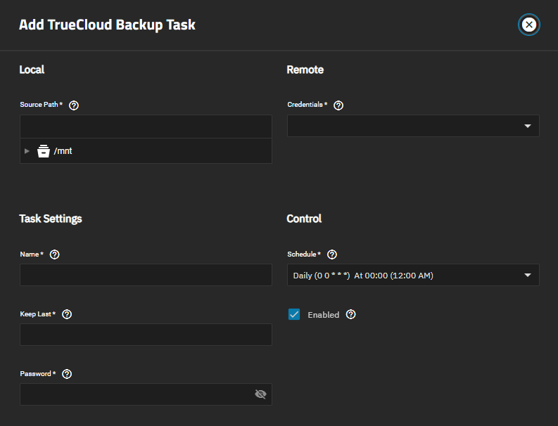
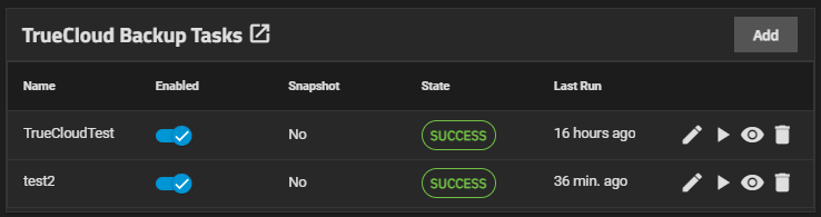
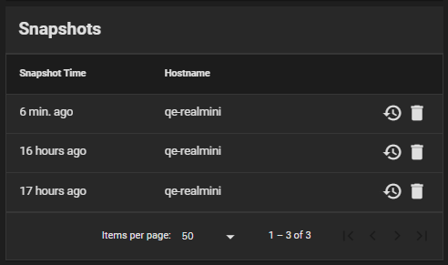
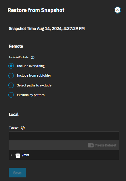
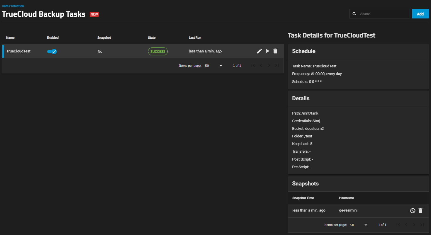
New TrueCloud Backup Tasks with streamlined functionality for Storj iX cloud backups and restoration.
New global search for finding pages and settings in the TrueNAS UI.
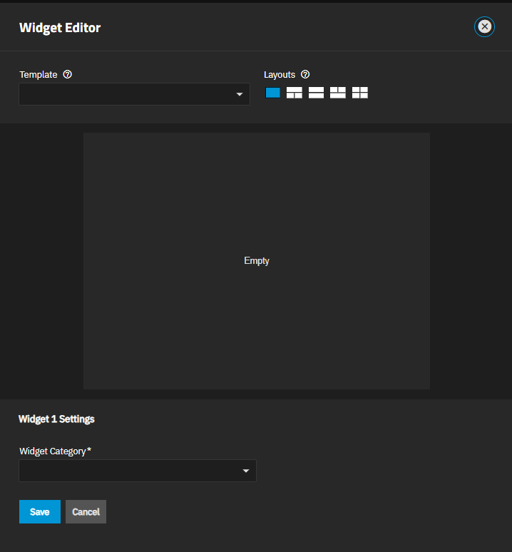
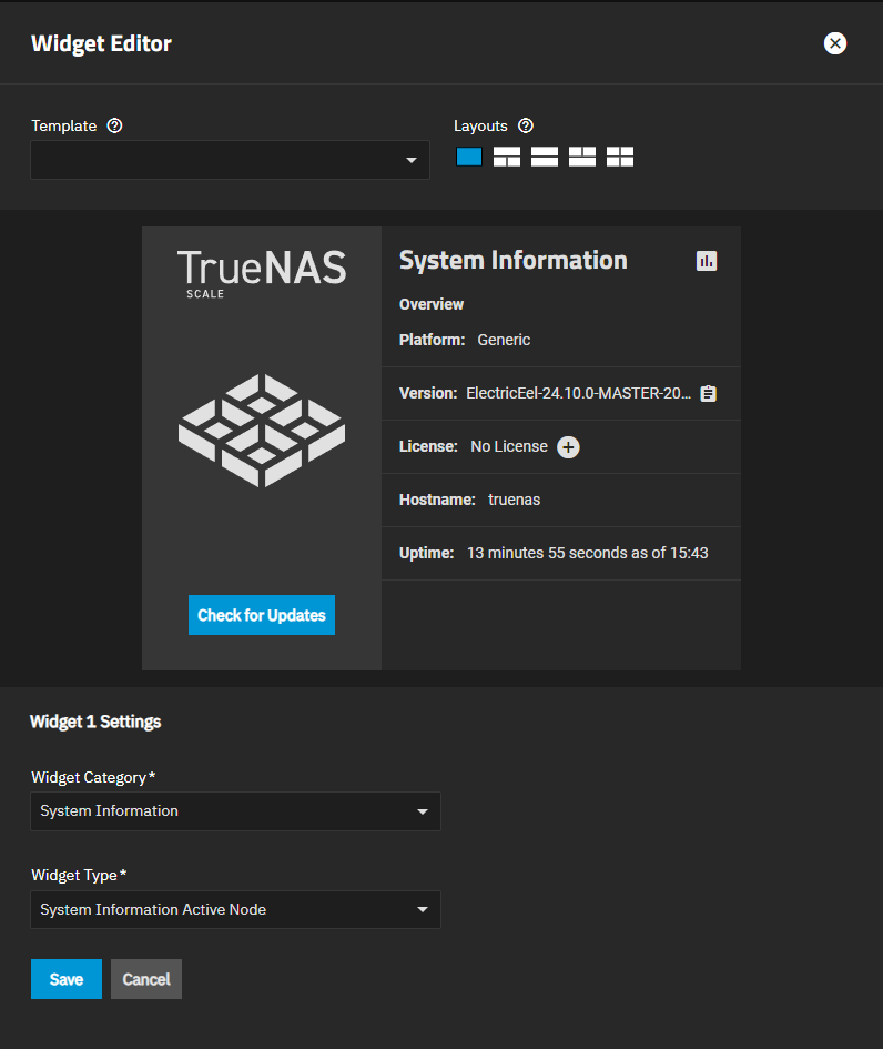
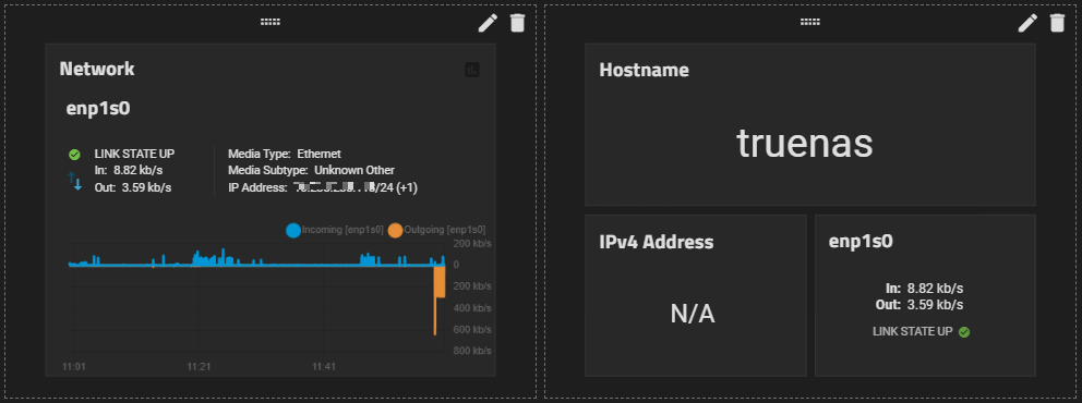
Dashboard reworked with more widgets, data reporting, and customization.
Rewrite TrueNAS installer to better support future development efforts.
Polish UI table presentation and integrate with global search (NAS-127222).
Replace nslcd with sssd to improve Kerberos, NFS, and SMB support in non-AD environments (NAS-127073).
Generate a unique system ID for each install (NAS-123519).
ZFS Fast Deduplication (OpenZFS feature sponsored by iXsystems): This feature is partially present in TrueNAS, but is considered experimental and disabled by default in 24.10. Full UI integration is anticipated in a future TrueNAS release (NAS-127088).
24.10 (Electric Eel) Featured Content
To view or search through documentation for previous TrueNAS major versions, use the Version dropdown at the top of this page.
This section guides you through installing TrueNAS SCALE, or migrating from CORE to SCALE, and using the UI to access and configure TrueNAS SCALE.
Configuration includes setting up initial storage, backup, and data sharing, and expanding TrueNAS with different application solutions.
The SCALE Evaluation Guide also provides video tutorials for installing and exploring the full potential of TrueNAS SCALE.
TrueNAS SCALE Getting Started Contents
⎙ Download or Print: View all SCALE Getting Started articles as a single page for download or print.
SCALE Hardware Guide: Provides information on system hardware and minimum requirements (CPU, memory, etc.). Covers storage considerations, media, controllers, device sizing and cooling, SAS expanders.
Third-Party Data Migration: Provides data migration instructions for users wanting move data from a third-party NAS solution to the SCALE NAS system storage using the Syncthing Enterprise app.
TrueNAS released 24.10 (Electric Eel) on December 17, 2024. This version received its final update on August 7, 2025. The terminal version of Electric Eel is 24.10.2.4.
Features
24.10 (Electric Eel) brought many new features and improvements to the TrueNAS experience:
The TrueNAS Apps feature backend moves from Kubernetes to Docker to streamline App deployment and management (announcement). Custom App deployment of Docker images is available via a guided wizard or a Compose YAML file.
Extend a RAIDZ vdev with individual disks (OpenZFS feature sponsored by iXsystems).
New TrueCloud Backup Tasks with streamlined functionality for Storj iX cloud backups and restoration.
New global search for finding pages and settings in the TrueNAS UI.
Dashboard reworked with more widgets, data reporting, and customization.
Rewrite TrueNAS installer to better support future development efforts.
Polish UI table presentation and integrate with global search (NAS-127222).
Replace nslcd with sssd to improve Kerberos, NFS, and SMB support in non-AD environments (NAS-127073).
Generate a unique system ID for each install (NAS-123519).
ZFS Fast Deduplication (OpenZFS feature sponsored by iXsystems): This feature is partially present in TrueNAS, but is considered experimental and disabled by default in 24.10. Full UI integration is anticipated in a future TrueNAS release (NAS-127088).
TrueNAS releases follow a general adoption guideline for their lifetime.
Starting with the NIGHTLY builds, each stage of a major release incorporates more testing cycles and bug fixes that represent a maturation of the release.
With each version release stage, users are encouraged to install, upgrade, or otherwise begin using the major version, depending on the specific TrueNAS deployment and use case:
Release Stage
Completed QA Cycles
Typical Use
Description
NIGHTLY
0
Developers
Incomplete
ALPHA
1
Testers
Not much field testing
BETA
2
Enthusiasts
Major Feature Complete, but expect some bugs
RC
4
Home Users
Suitable for non-critical deployments
RELEASE
6
General Use
Suitable for less complex deployments
U1
7
Business Use
Suitable for more complex deployments
U2+
8
Larger Systems
Suitable for higher uptime deployments
Visit the TrueNAS Software Status page for recommendations on which software version to use, tailored to user types ranging from Developer to Mission Critical.
Upgrade Notes
TrueNAS is an appliance built from specific Linux packages.
Updating TrueNAS using apt or any method other than the TrueNAS web interface can make the system inoperable.
Modifying the base OS can cause unexpected behavior during upgrades:
Users who manually installed Docker on TrueNAS 24.04 or earlier can experience TrueNAS Apps failure in 24.10 or later.
This occurs due to conflicts between the manually installed and native Docker configurations.
Affected systems can encounter app_lifecycle.compose_action errors, such as: 'group_add[0]' expected type 'string', got unconvertible type 'int', value: '568'
All auxiliary parameters can experience changes between TrueNAS major versions due to security and development changes.
We recommend removing all auxiliary parameters from TrueNAS configurations before upgrading as these settings can result in SMB share failures after an upgrade.
After updating, clear the browser cache (CTRL+F5) before logging in to SCALE. This ensures stale data doesn’t interfere with loading the SCALE UI.
24.10 moves the applications backend from Kubernetes to Docker (announcement).
All applications available from official catalogs in 24.04 are available to install in 24.10.
Supported catalog applications automatically migrate to Docker deployments on upgrade from from 24.04 (Dragonfish) to Electric Eel.
Applications from third-party catalogs, such as TrueCharts, do not automatically migrate to 24.10.
See Preparing for App Migration below for more information.
Custom applications based on Docker images can be installed using the installation wizard or a Docker Compose YAML file.
See Installing Custom Apps for more information.
Automatic app migration on upgrade from 24.04 is at parity for all official catalog applications.
A few applications might require manual migration steps, depending on the options enabled in 24.04.
For more information, see the comments for Home Assistant and Tailscale.
During the migration process, 24.10 creates a hidden Docker dataset on the apps pool that is mounted at /mnt/.ix-apps.
TrueNAS then reads the stored Kubernetes app data in the previous ix-applications dataset, ports them to Docker, and saves them in the new Docker dataset.
App storage ix-volumes present in ix-applications are cloned under the new Docker dataset and promoted.
Because the previous ix-applications dataset is retained as is, 24.10 maintains the ability to roll back to your previous Dragonfish installation.
You can re-initiate a failed migration of any previously-installed Kubernetes apps to Docker at any time after upgrading to Electric Eel.
From a shell session enter
midclt call -job k8s_to_docker.migrate poolname, where poolname is the name of the applications pool, for example tank.
Custom applications installed using the TrueNAS UI in 24.04 automatically migrate on upgrade to 24.10.
Custom applications with nonstandard networking, such as an external interface attached, migrate, but the interface configuration is discarded.
Users can either use the base networking as is or configure custom Docker networking using a YAML custom app deployment, Dockge, or Portainer.
Starting in 24.10, TrueNAS does not include a default NVIDIA GPU driver and instead provides a simple NVIDIA driver download option in the web interface.
This allows for driver updates between TrueNAS release versions.
Users can enable driver installation from the Installed applications screen.
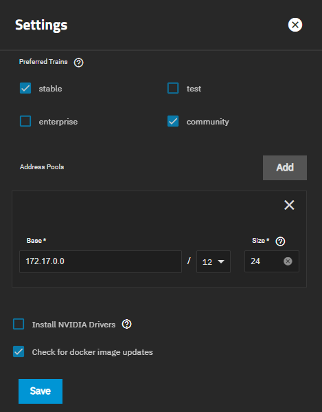
Click Configure > Settings and select Install NVIDIA Drivers.
This option is only available for users with a compatible NVIDIA GPU and no drivers installed or for users who have previously enabled the setting.
Support for the deprecated LDAP Samba Schema is removed in 24.10.
Users with both LDAP and SMB shares configured should migrate legacy Samba domains to Active Directory before upgrading to 24.10.
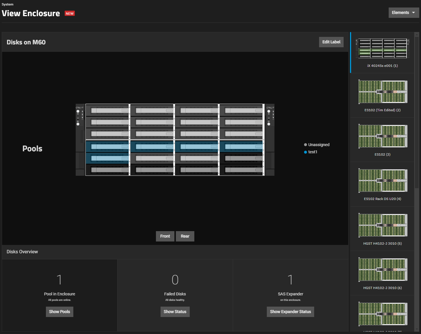
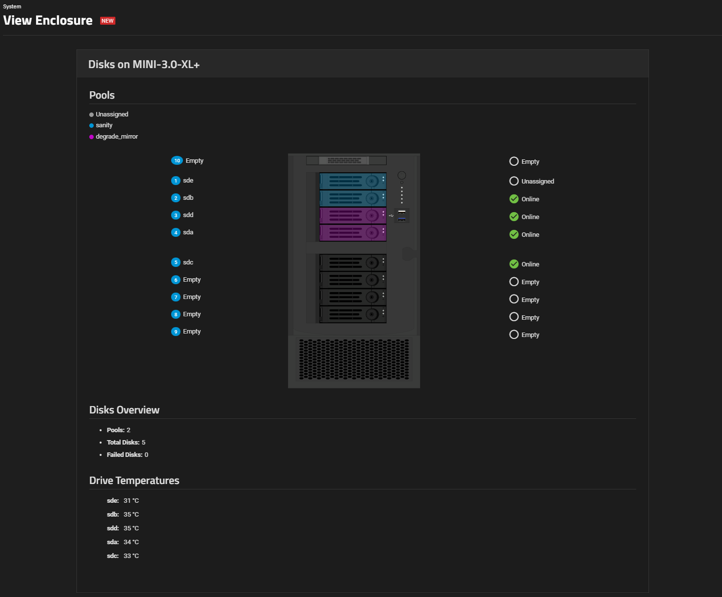
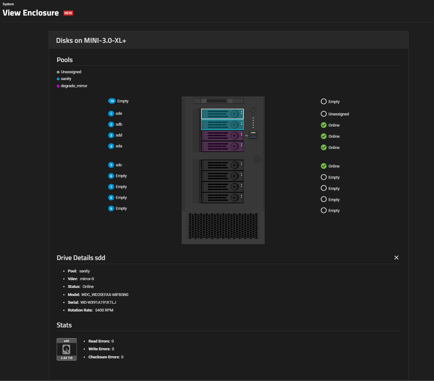
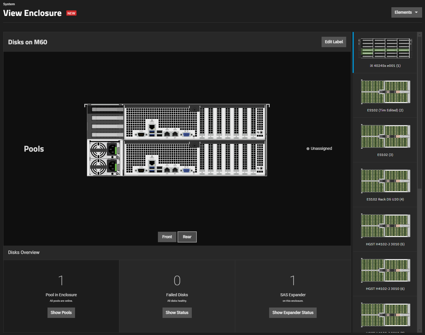
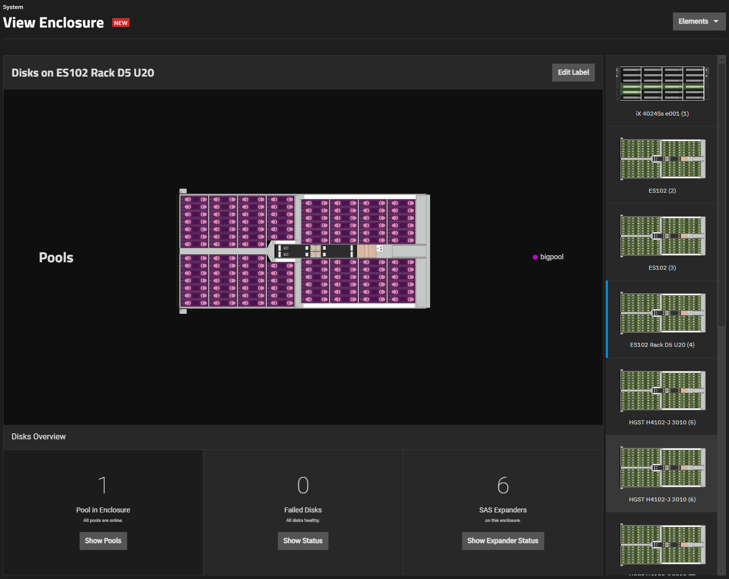
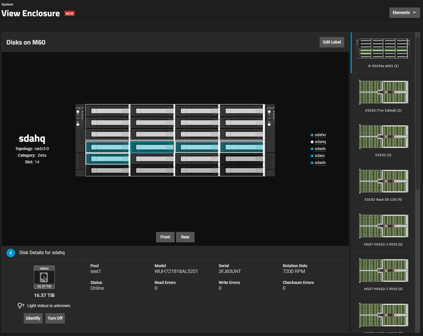
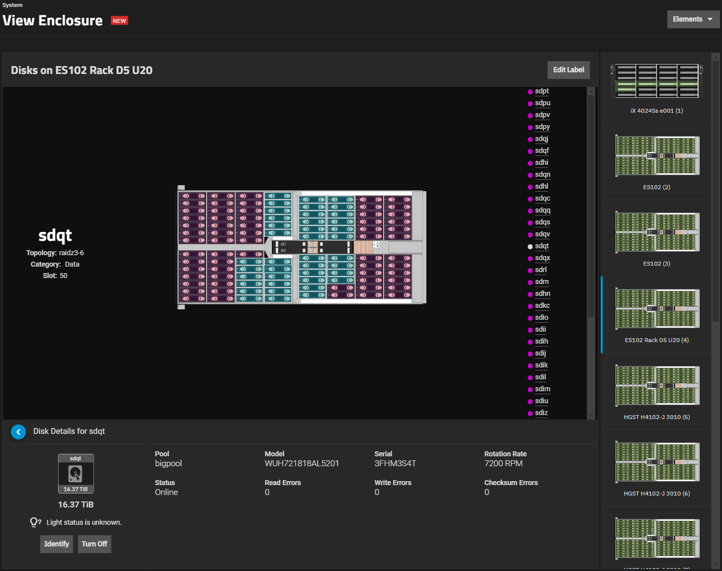
Electric Eel introduces redesigns of the UI Dashboard and View Enclosure screens with numerous improvements to system and enclosure management.
The legacy Dashboard and View Enclosure screens are removed in the RC.1 release version.
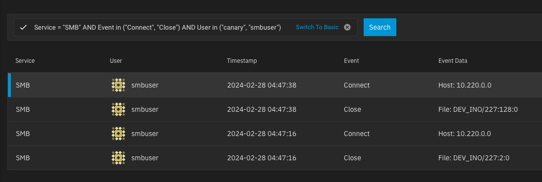
SMB audit log entries are omitted by default from the System > Audit screen.
To view SMB audit results, go to System > Services and click receipt_longAudit Logs for the SMB service or use advanced search on the main Audit screen to query SMB events.
TrueNAS Apps
TrueNAS Apps
Application maintenance, including version updates, features, and configuration options, is independent from TrueNAS version release cycles. See documentation and resources at the TrueNAS Apps Market and the truenas/apps repository issues tracker for more information.
TrueNAS Apps Support Timeline for 24.04 and 24.10
Summary:
Applications added to the TrueNAS Apps catalog before December 24, 2024, require updates to enable host IP port binding.
These updates roll out on June 1, 2025, and require TrueNAS 25.04 (or later).
Due to breaking changes involved in enabling host IP port binding, June 1, 2025 is the deadline for automatic apps migration on upgrade.
Migrate from 24.04 to 24.10 before June 1, 2025, to ensure automatic app migration.
Upgrade to 24.10.2.2 or 25.04 before June 1 to continue receiving regular app updates.
Previously installed apps on TrueNAS 24.10.2.1 (or earlier) do not receive updates after this point.
Normal application update functionality resumes after TrueNAS updates to 24.10.2.2 or 25.04.
Timeframe
App Migration 24.04 → 24.10
App Updates in 24.10
App Migration 24.10 → 25.04
App Updates in 25.04
Before June 1, 2025
✅ Supported
✅ Supported
✅ Supported
✅ Supported
After June 1, 2025
❌ Not Supported
✅ Supported (24.10.2.2 or later)
✅ Supported
✅ Supported
Read More
Application host IP port binding is being developed for all applications in the TrueNAS Apps catalog.
This feature allows per-app selection of any IP address from the available aliases assigned to an interface to bind the WebUI port to.
It includes port bind mode options to publish the port for external access or expose it for inter-container communication.
A small but growing list of applications currently support this functionality in TrueNAS 24.10 or later.
However, applications that were in the TrueNAS Apps catalog before implementation of this feature require OS-level changes to enable support.
Catalog updates to provide host IP port functionality to these applications are scheduled for June 1, 2025.
Applications that currently support host IP port binding
All applications added to the TrueNAS Apps catalog after December 24, 2024 support host IP port binding. As of May 9, 2025, these applications include:
ArchiSteamFarm
Arti
Authelia
Authentik
Bitcoind
Calibre Web
Change Detection
Channels DVR
Cockpit WS
Code Server
Codegate
Concourse
ConvertX
Crafty 4
Dozzle
Duplicati
Electrs
Emby
ESPHome
Flood
Forgejo
Gitea Act Runner
Glances
Handbrake Web
Heimdall
Homearr
Homebox
I2P
InfluxDB
Invoice Ninja
IT Tools
IX Remote Assist
Jackett
JDownloader2
Jelu
Karakeep
Kasm Workspaces
Lyrion Music Server
Minecraft Bedrock
Open Speed Test
Outline
Playwright
Romm
Satisfactory Server
Scrypted
Spottarr
Steam Headless
Stirling PDF
Terreria
Tianji
TrueNAS WebUI
TVHeadend
Umami
Unmanic
UrBackup
Versity Gateway
Warracker
Windmill
Wyze Bridge
Zigbee2MQTT
All applications added after this date also support this feature.
Applications that do not currently support host IP port binding
Actual Budget
Adguard Home
Asigra DS System
Audiobookshelf
Autobrr
Bazarr
Briefkasten
Calibre
Castopod
Chia
ClamAV
Collabora
Dashy
DDNS Updater
Deluge
Diskoverdata
Distribution
Dockge
Drawio
Eclipse Mosquitto
Elastic Search
Emby
Filebrowser
Filestash
Firefly III
Flame
Flaresolverr
FreshRSS
Frigate
FSCrawler
Gaseous Server
Gitea
Grafana
Handbrake
Home Assistant
Homepage
Homer
Immich
Invidious
IPFS
IX App (Custom App)
Jellyfin
Jellyseerr
Jenkins
Joplin
Kapowarr
Kavita
Komga
Lidarr
Linkding
Listmonk
Logseq
Mealie
Metube
Minecraft
Minecraft Bedrock
MineOS
MinIO™
Mumble
N8N
Navidrome
NetbootXYZ
Netdata
Nextcloud
Nginx Proxy Manager
Node RED
Odoo
Ollama
Omada Controller
Open Speed Test
Open WebUI
Organizr
Outline
Overseerr
Palworld
Paperless NGX
Passbolt
Penpot
PGAdmin
Photoprism
PiGallery2
PiHole
Piwigo
Planka
Plex
Portainer
Postgres
Prometheus
Prowlarr
Qbittorrent
Radarr
Readarr
Redis
Romm
Roundcube
Rsyncd
Rust Desk
Satisfactory Server
Sabnzbd
Scrutiny
SearxNG
Scrypted
SFTPGo
Sonarr
Storj
Syncthing
Tautulli
TDarr
Terraria
TFTPD HPA
Tiny Media Manager
Transmission
TrueNAS WebUI
Twofactor Auth
Unifi Controller
Umami
Uptime Kuma
UrBackup
Vaultwarden
Versitygw
Vikunja
Warracker
WebDAV
WG Easy
Whoogle
Windmill
Wordpress
Wyze Bridge
Zigbee2MQTT
These applications update to support host IP port binding on June 1, 2025.
App Migration from 24.04 to 24.10
TrueNAS 24.10 introduced a new Docker-based TrueNAS Apps backend and automated migration for Kubernetes-based apps on upgrade.
Due to breaking changes involved in enabling host IP port binding, June 1, 2025 is the deadline for automatic apps migration on upgrade.
Any users still running TrueNAS Apps on 24.04 after June 1 must re-deploy those apps after upgrading to 24.10 or later.
App Updates in 24.10
Update to TrueNAS 24.10.2.2 before June 1, 2025 to continue receiving app updates without interruption, including the new IP port binding functionality.
Previously installed apps on TrueNAS 24.10.2.1 (or earlier) do not receive updates after this point.
Normal application update functionality resumes after TrueNAS updates to 24.10.2.2 or 25.04.
App Updates in 25.04
Users of TrueNAS 25.04 continue receiving app updates without interruption, including the new IP port binding functionality.
Applications installed on TrueNAS 25.04 before June 1, 2025 automatically update to enable the new functionality.
No manual management is required.
Preparing for App Migration
To prepare applications for migration from Kubernetes to Docker, address the following configurations before upgrading to 24.10:
Configuration
Action Needed
Outdated Applications
Update all applications to the latest available version in the TrueNAS catalog before migrating.
Host Path ACLs
Users with applications installed on 24.04 using host path volume mounts with Enable ACL selected and ACL Entries defined in the app configuration, must go to the Edit Application screen and set the Force Flag checkbox under ACL Options before updating to 24.10. This ensures the app fully migrates and does not encounter issues when the mount point has existing data.
Encrypted Dataset
TrueNAS shows a warning and explains that applications do not migrate to 24.10 when the ix-applications dataset is configured on a pool with an encrypted dataset (see NAS-131561). Relocate installed applications to an unencrypted pool on 24.04 before attempting to upgrade to 24.10. TrueNAS does attempt to migrate predefined encrypted host mount paths.
Third Party Applications
Applications from third-party catalogs, such as TrueCharts, do not support automatic migration to 24.10. Migration of third-party applications generally requires manual data backup and redeployment.
Third-party catalogs are provided, maintained, and supported by individuals or organizations outside of iXsystems. Refer to the catalog maintainer or the TrueNAS Community forums for migration support.
Container Dependent Network Settings
Applications do not migrate if TrueNAS network settings are configured to depend on any client container or application hosted on the TrueNAS system, such as DNS services, proxy networks, firewalls, and routers (see NAS-131553). This is an unsupported configuration because TrueNAS cannot access the necessary networks during boot if the client container has not started.
Upgrade Paths
With a stable release, upgrading to TrueNAS 24.10 (Electric Eel) from an earlier release is primarily done using the web interface update process.
Another upgrade option is to use an .iso file to perform a fresh install on the system and then restore a system configuration file.
The chart below shows recommended paths for upgrading from earlier TrueNAS versions.
Update the system to the latest maintenance release of the installed major version before attempting to upgrade to a new major version.
Permitted upgrade methods are:
update: apply an automatic update using the Update screen in the TrueNAS UI or install a manual update file. Some upgrade paths do not support these options (see chart).
ISO install: save a current TrueNAS configuration file, perform a fresh install using an .iso file for the target version, and then upload the previously saved configuration.
Users can skip major versions with a fresh ISO install followed by a configuration file upload.
Carefully review release notes for each skipped major version before upgrading, noting any service deprecations or significant changes that impact the previous configuration.
Consider stopping at major versions with significant impacts to address changes before continuing the upgrade path or be prepared to manually reconfigure incompatibilities on the latest target version.
This chart shows the basic update path to and from the latest release of each TrueNAS major version.
Depending on your use case and risk tolerance, some users may prefer to remain on an earlier minor or major version for a period of time before updating.
Visit the TrueNAS Software Status page for recommendations on which software version to use, tailored to user types ranging from Developer to Mission Critical.
            flowchart LR
              A["11.3-U5"] -->|update| B["12.0-U8.1"]
              B -->|"update / ISO install"| C["13.0-U6.8 / 13.3-U2"]
              C -->|update| G
              C -->|ISO install| I
              D["22.02.4 (Angelfish)"] -->|update| E
              E["22.12.4.2 (Bluefin)"] -->|update| F
              F["23.10.2 (Cobia)"] -->|update| G
              G["24.04.2.5 (Dragonfish)"] -->|update| H
              H["24.10.2.4 (Electric Eel)"] -->|update| I
              I["25.04.2.4 (Fangtooth)"] -->|"(anticipated)"| J
            J["25.10 (Goldeye)"]
            flowchart LR
              A["11.3-U5"] -->|update| B
              B["12.0-U8.1"] -->|update| C
              C["13.0-U6.8"] -->|ISO install| G
              C -->|update| E
              D["23.10.2 (Cobia)"] -->|update| E
              E["24.04.2.5 (Dragonfish)"]  -->|update| F
              F["24.10.2.4 (Electric Eel)"] -->|update| G
              G["25.04.2.4 (Fangtooth)"] -->|"(anticipated)"| H
            H["25.10 (Goldeye)"]
Migrating from TrueNAS CORE
TrueNAS Enterprise
Enterprise customers should contact iXsystems Support for assistance with migrating.
iXsystems Support
When attempting to migrate from TrueNAS 13.0 (or 13.3 for community members), the general recommendation is to back up the system configuration file and use an .iso file to fresh install TrueNAS.
Upgrade your system to the latest publicly-available 13.0-U6.2 (or later) release before attempting to migrate.
After install, restore the system configuration and import the pools.
Depending on the specific system configuration, this can be a straightforward or complicated process.
See the Migration articles for cautions and notes about differences between each software and the migration process.
The only path to side-grade or migrate from 13.0-U6.2 or 13.3 is to install or upgrade to 24.04 (latest).
TrueNAS 24.10 and later releases do not support migrations from 13.X. These migrations cannot be done, and either fail or result in error conditions that cannot be resolved.
Download the iso for the latest maintenance release of TrueNAS 24.04 (see Software Releases) and follow the instruction articles in this section.
Enterprise customers should contact Support for assistance with migrating.
Component Versions
Component version numbers below are current as of the latest TrueNAS 24.10 release.
Click the component version number to see the latest release notes for that component.
TrueNAS integrates many features provided by the upstream OpenZFS project.
Any new feature flags introduced since the previous OpenZFS version that was integrated into TrueNAS (OpenZFS 2.1.11) are listed below:
The TrueNAS team is pleased to release TrueNAS 24.10.2.4!
This maintenance release contains a fix for Enterprise that makes HA environments more robust in situations where upstream network configurations are incorrect for the HA environment.
24.10.2.4 also contains optimizations for debug generation.
24.10.2.3
July 14, 2025
The TrueNAS team is pleased to release TrueNAS 24.10.2.3!
This maintenance release contains a single change to prevent Active Directory interruptions for TrueNAS systems using the “AD” idmap backend (NAS-135515).
See the linked NAS ticket for more information.
24.10.2.2
May 13, 2025
The TrueNAS team is pleased to release TrueNAS 24.10.2.2!
This maintenance release is intended to assist the community with the TrueNAS Apps transition to per-app IP address binding.
It contains a single change to backport app update logic from TrueNAS 25.04, allowing users who prefer to remain on 24.10 past the June 1 app migration cut-off to do so (NAS-135515).
See TrueNAS Apps in the 24.10 Upgrade Notes for more information.
Known Issues
An update to the Microsoft Netlogon RPC protocol affects systems using the “AD” idmap backend for Active Directory. Users are not able to connect to the SMB service provided by Samba for any domain configured to use the “AD” idmap backend.
A fix is expected in the TrueNAS 24.10.2.3 release.
24.10.2.1
April 3, 2025
The TrueNAS team is pleased to release TrueNAS 24.10.2.1!
This maintenance release is focused on fixing a few OpenZFS-related priority issues that impact 24.10.2.
Notable Changes
Error with device removal and block pointers remap with cloned blocks NAS-133555.
ZED fails to activate a hot spare if a device is removed by the kernel NAS-135033.
An OpenZFS patch was also submitted.
24.10.2
January 28, 2025
iXsystems is pleased to release TrueNAS 24.10.2!
This is a maintenance release and includes refinement and fixes for issues discovered or outstanding after the 24.10.1 release.
Notable Changes
Do not retrieve hidden zpool properties in py-libzfs by default (NAS-132988). These properties include name, tname, maxblocksize, maxdnodesize, dedupditto and dedupcached. Users needing these properties can see the linked ticket for the zpool command to retrieve them.
A Force Remove iXVolumes checkbox is exposed on app deletion for any apps migrated from 24.04 that were unable to be deleted due to a “dependent clones” error (NAS-132914).
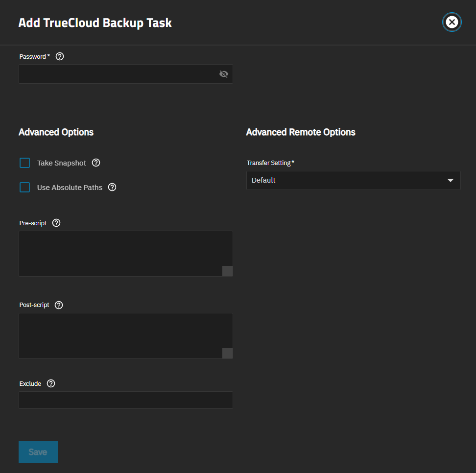
New cloud backup option: Use Absolute Paths (NAS-132920).
Fix loading the nvidia_drm kernel module to populate the /dev/dri directory for NVIDIA GPU availability in apps like Plex (NAS-133250).
Fix netbiosname validation logic if AD enabled (NAS-133167).
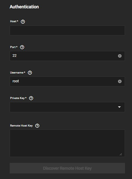
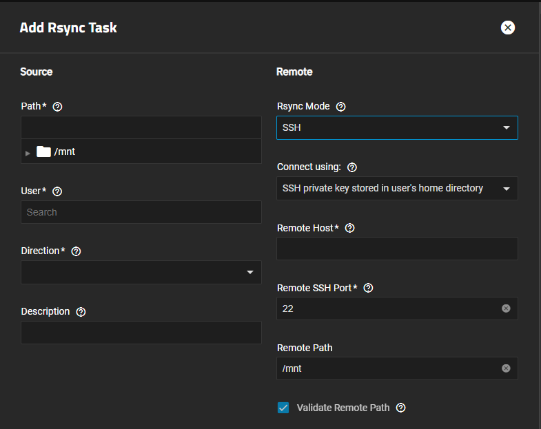
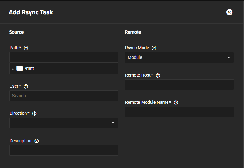
Disallow specifying SSH credentials when rsync mode is MODULE (NAS-132874 and NAS-132928).
Simplify CPU widget logic to fix reporting issues for CPUs that have performance and efficiency cores (NAS-133128).
Properly support OCI image manifest for registries other than Docker (NAS-133046).
Remove explicit calls to the syslog.syslog module (NAS-132657).
Fix an ACL Editor Group/User Search Bug (NAS-131841).
Prevent infinite recursion on corrupted databases when deleting network interfaces (NAS-132567).
Clean up FTP banner to prevent Reolink camera failures (NAS-132701).
Refresh cloud sync credentials even if cloud sync task fails (NAS-132851).
To switch between detail and list views for the changelog, press t.
Open the changelog in Jira to see the Export menu to print or download the changelog in various file formats.
Known Issues
We are aware of an issue affecting SED disk unlock at boot, particularly for systems configured with per-disk SED passwords.
A fix is expected in the TrueNAS 25.04 release.
Some users who have applications with have NVIDIA GPU allocations report the error Expected [uuid] to be set for GPU inslot [<some pci slot>] in [nvidia_gpu_selection]) (see NAS-132086).
Users experiencing this error should follow the steps below for a one time fix that should not need to be repeated.
Connect to a shell session and retrieve the UUID for each GPU with the command midclt call app.gpu_choices | jq.
For each application that experiences the error, run midclt call -job app.update APP_NAME '{"values": {"resources": {"gpus": {"use_all_gpus": false, "nvidia_gpu_selection": {"PCI_SLOT": {"use_gpu": true, "uuid": "GPU_UUID"}}}}}}'
Where:
APP_NAME is the name you entered in the application, for example “plex”.
PCI_SLOT is the pci slot identified in the error, for example “0000:2d:00.0”.
GPU_UUID is the UUID matching the pci slot that you retrieved with the above command.
iXsystems is pleased to release TrueNAS 24.10.1!
This is a maintenance release and includes refinement and fixes for issues discovered after the 24.10.0 and 24.10.0.X releases.
Notable Changes
The sendmail command is removed for security reasons (NAS-133174). Users previously using sendmail as part of their custom scripting should use exim instead.
The boot pool is now properly enforcing the default setuid and noexec options (NAS-127825). This restores the default boot pool behavior to be restricted from general use. Users that are currently attempting to exec scripts from a /home or other boot pool location should move these to a data pool location.
Fix issue with zpl_get_name (NAS-132930). This can improve performance in some specific NFS workloads with large directories (see the commit for more details).
Rework Dashboard CPU widgets to show metrics per physical core (NAS-131839).
Prevent incorrect translation of LDAP Base DN to kerberos realm (NAS-132192).
Increase the maximum permitted Samba (SMB) ACL size from 64 to 1024 entries (NAS-132344).
Prevent applications service failing after upgrade if an app requires an Nvidia GPU (NAS-132070 and NAS-132131).
Cache installed Nvidia kernel modules on upgrades within the same release train (i.e. 24.10.0, 24.10.1, etc.) so they do not need to be reinstalled and compiled (NAS-132359).
Allow limited administrative users to view and download logs of certain jobs, even if they did not initiate the job (NAS-132031).
Ensure installed apps are shown correctly after system reset (NAS-131913).
Prevent KeyError: 'pool_name' resulting from pool name collision in zpool.status (NAS-132742).
Allow unsetting/changing the apps pool in cases where the ix-apps dataset no longer exists (NAS-132065).
Fix memory context for IPC read allocations to prevent potential Use After Free (UAF) corruption (NAS-132685).
Make sure helm secret is safely serialized when listing App backups to migrate (NAS-132077). This fix prevents a Unicode decode error, Failed to list backups: 'utf-8' codec can't decode byte 0xa6 in position 0: invalid start byte, that prevented some users from migrating apps from 24.04 to 24.10.0.X versions.
To switch between detail and list views for the changelog, press t.
Open the changelog in Jira to see the Export menu to print or download the changelog in various file formats.
Known Issues
The Plex app doesn’t show Nvidia GPUs being passed to the app and transcode stops working (NAS-133250). A fix is anticipated in a future release and the linked Jira ticket has a workaround for the 24.10.1 release.
Configured SED drives do not migrate from FreeBSD-based TrueNAS releases to 24.10 (or earlier) releases, due to differences in how FreeBSD-based and Linux-based TrueNAS releases manage SED configurations. A fix to allow cleaner migrations of SED configurations is anticipated in TrueNAS 25.04.
The Dashboard CPU widgets have an issue displaying metrics for some types of hyper-threaded CPUs (NAS-133128). This is being addressed in future 24.10 maintenance releases.
An issue was discovered with restoration of ZFS snapshots via TrueCloud back up tasks (NAS-132608). The Take Snapshot option for TrueCloud back up tasks is disabled in 24.10.1 until the underlying issue is addressed in a future TrueNAS release.
OAuth support for Microsoft Outlook is no longer supported in 24.10 due to Microsoft removal of username and password authentication to their email server. Restoration of Outlook OAuth support is anticipated in the 25.04 release version (NAS-132807).
An issue has been discovered for cloud sync tasks configured with Filename Encryption, which is available in Advanced Remote Options (NAS-132472). As this is an upstream issue in rclone, we recommend that users should not create new cloud sync tasks with Filename Encryption enabled. Existing users of this feature must leave it enabled for existing cloud sync tasks to be able to recover backups.
Some users report an error when trying to delete applications that previously migrated from 24.04 to 24.10 and are configured with ixVolumes (NAS-131911). Attempting to delete an affected app returns the error Failed to delete dataset: cannot destroy 'POOL/ix-apps/app_mounts/APPNAME': filesystem has dependent clones. A fix is expected in the 24.10.2 release (NAS-132914).
VMs might not start due to an issue with memory allocation and the ZFS cache (NAS-128544). This is resolved in the upcoming TrueNAS 25.04 version.
If an SMB or NFS bind IP address is set and an administrator changes the host system IP without first removing the current NFS and/or SMB bind IP, the UI does not display the current NFS and/or SMB bind ip address(es) and provides no mechanism for unsetting the bad IP address (NAS-133049). This breaks functionality of the NFS and/or SMB service.
Users who encounter this bug can manually remove the existing bind IP address(es) and then use the TrueNAS UI to reconfigure bind IP addresses.
Connect to a TrueNAS shell session and enter one or both of these command(s), as needed:
midclt call smb.update '{"bindip": []}' to clear the SMB bind address(es)
midclt call nfs.update '{"bindip": []}' to clear the NFS bind address(es)
A UI fix for this issue is expected in a future release.
TrueNAS Enterprise
An issue was found with configuring Chelsio T580 NICs in different modes with TrueNAS 24.10.1. This is under investigation and a fix is forthcoming in a future 24.10 maintenance release.
iXsystems is pleased to release TrueNAS 24.10.0.2!
This is a release to address another high-impact issue discovered with SMB memory management.
Fix Management of SMB AIO read buffers (NAS-132365).
Users with 24.10.0.1 installed and SMB shares in use are encouraged to upgrade to this release immediately.
Known Issues
Please see the 24.10.0 changelog below and use the Jira filter links to see the full changelog and known issues related to the 24.10.0, 24.10.0.1, and 24.10.0.2 releases.
24.10.0.1
Click to expand
November 7, 2024
iXsystems is pleased to release TrueNAS 24.10.0.1!
This is a release to address a small number of issues discovered in the 24.10.0 release.
Notable Changes
Fix memory consumption related to SMB AIO reads (NAS-132166).
Users have reported an issue with SMB memory management under heavy SMB loads.
A fix for this issue is in the 24.10.0.2 release version.
Please see the 24.10.0 changelog below and use the Jira filter links to see the full changelog and known issues related to the 24.10.0 and 24.10.0.1 releases.
24.10.0
Click to expand
October 29, 2024
iXsystems is pleased to release TrueNAS 24.10.0!
This is the first stable release of TrueNAS SCALE 24.10 (Electric Eel).
It includes numerous software component updates and polished features, as well as fixes for issues discovered in 24.10-RC.1 and 24.10-RC.2.
Rewrite enclosure plugin in 24.10 to match performance improvements in 13.3 (NAS-123474).
Prevent phantom partitions that TrueNAS erroneously reported as disconnected pools (NAS-131171).
Revised Docker networking logic for applications (NAS-131617).
Enable editing of custom YAML applications (NAS-131147).
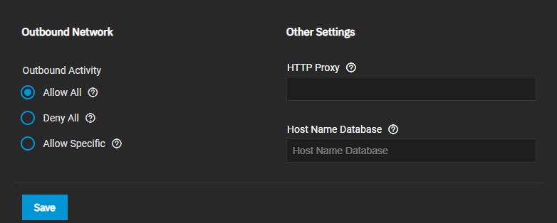
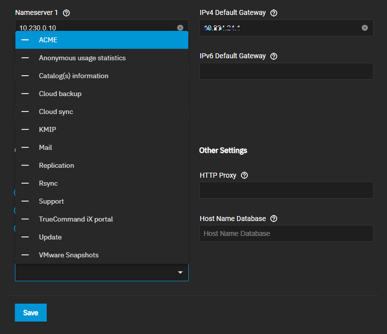
Prevent the TrueNAS UI from sending an improper payload for the Outboard Activity option when re-saving an edit to global network settings (NAS-131787).
When moving from an existing applications pool to a new pool, TrueNAS does not present the option to Migrate applications to the new pool because the underlying functionality is not present in the new Docker apps framework (NAS-131610). Users who need to redeploy the applications pool can either choose to leave existing applications on the previous location, remove existing applications and reinstall on the new pool, or manually relocate and clean up data.
Documentation Hub Update: To reflect the continuing process of application maintenance and updates as separate from TrueNAS major version releases, all application Tutorials are moved from the Tutorials section in TrueNAS version documentation to a dedicated and unversioned TrueNAS Apps section.
Community contributions to TrueNAS Apps documentation are highly encouraged!
The Community Apps documentation is pre-populated with placeholder templates for each application available in the TrueNAS Community train and ready to accept Pull Requests.
See Contributing to TrueNAS Application Documentation for more information.
To switch between detail and list views for the changelog, press t.
Open the changelog in Jira to see the Export menu to print or download the changelog in various file formats.
Known Issues
SED devices are not consistently unlocking on system restart (NAS-132518). Users are cautioned to avoid using SED devices in 24.10 or attempting to migrate a functional SED environment from TrueNAS 13.0-U6.3 (Enterprise) or TrueNAS 13.3-U1 (Community) until this issue is resolved.
A bug with sudo v1.9.13 causes commands like sudo su - and sudo su before starting tmux to break in TrueNAS 24.10.
Sudo v1.9.14 fixes this issue and is planned for inclusion in a future TrueNAS release.
Application Update Available tooltips display the current installed version as the available update version (NAS-131747). A fix for this issue is expected in the 24.10.1 release version.
Installed custom applications do not alert for available updates in the TrueNAS UI (NAS-132202). A fix for this issue is expected in the 24.10.1 release version.
Some users who have upgraded to 24.10.0 from a previous version, and who have applications with have NVIDIA GPU allocations, report the error Expected [uuid] to be set for GPU inslot [<some pci slot>] in [nvidia_gpu_selection]) (see NAS-132086).
Users experiencing this error should follow the steps below for a one time fix that should not need to be repeated.
Connect to a shell session and retrieve the UUID for each GPU with the command midclt call app.gpu_choices | jq.
For each application that experiences the error, run midclt call -job app.update APP_NAME '{"values": {"resources": {"gpus": {"use_all_gpus": false, "nvidia_gpu_selection": {"PCI_SLOT": {"use_gpu": true, "uuid": "GPU_UUID"}}}}}}'
Where:
APP_NAME is the name you entered in the application, for example “plex”.
PCI_SLOT is the pci slot identified in the error, for example “0000:2d:00.0”.
GPU_UUID is the UUID matching the pci slot that you retrieved with the above command.
Drives that have been formatted with previous TrueNAS versions can show exported pools in the TrueNAS UI (NAS-131890). This is typically due to obsolete filesystem labels in the boot drives still being detected by TrueNAS. The underlying bug is fixed in 24.10.0-RC.2 and newer, but these labels can remain on boot drives used with previous TrueNAS releases. Removing these labels from the boot drives requires backing up your TrueNAS configuration, reinstalling 24.10.0 fresh on the boot drives, then restoring the TrueNAS configuration.
If TrueNAS is updated to 24.10.0 from a previous 24.10 release candidate version and the Install Nvidia Drivers option is selected, TrueNAS downloads and installs drivers to the upgraded OS in the background before starting the Applications service (NAS-132070).
This can be a lengthy process with no UI progress feedback.
If a network interruption on boot prevents driver installation, TrueNAS does not retry and a manual workaround is required (see linked NAS issue for steps).
TrueNAS Enterprise
There is a known issue with the ES24 expansion shelf not displaying on the Enclosure Management screen in 24.10.0. A fix is anticipated in the next 24.10 release. In the meantime, customers with an ES24 shelf connected to their TrueNAS appliance should plan their 24.10 upgrade time frame for the first maintenance release, 24.10.1.
* Replication task (and possibly other Backup Task) logs aren't properly downloading for non-full admin users ([NAS-132031](https://ixsystems.atlassian.net/browse/NAS-132031)).
A full admin user can download these task logs and a fix for admin users with fewer permissions is pending in the 24.10.1 release.
* Some users report that after rebooting TrueNAS, the Installed applications screen does not display the apps that are installed and states **Applications are not running**.
Users encountering this issue can refresh the web page to correct it.
Early releases are intended for testing and feedback purposes.
Do not use early release software for critical tasks.
October 4, 2024
iXsystems is pleased to release TrueNAS 24.10-RC.2!
This is a small hot fix to correct applications-related issues discovered after the release of 24.10-RC.1.
Notable Changes
Revised Docker networking logic to prevent users with 15 or more applications installed encountering network exhaustion, which resulted in the apps service failing to initialize (NAS-131485).
Please use the 24.10-RC.1 Jira filter links below to see the full changelog and known issues related to the 24.10 release candidates.
24.10-RC.1
Click to expand
Early releases are intended for testing and feedback purposes.
Do not use early-release software for critical tasks.
October 2, 2024
iXsystems is pleased to release TrueNAS 24.10-RC.1!
This release candidate version has software component updates and new features that are in the polishing phase as well as fixes for issues discovered in 24.10-BETA.1.
Notable Changes
Convert audit message_timestamp for sudo to UTC (NAS-130373).
The previous Dashboard and View Enclosure UI screens are removed (NAS-130582).
Prevent incorrect auto-populated portal group IDs on iSCSI target (NAS-130656).
All administrators receive a daily alert for all login failures by any account to the TrueNAS UI or API (NAS-127040).
Enterprise administrators also receive a daily alert for all successful logins by default administrator accounts (root / admin / truenas_admin).
Prevent systemd journal from producing duplicate audit entries on upgrade (NAS-131125).
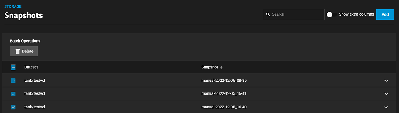
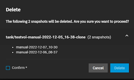
Ensure snapshot batch deletion targets only selected snapshots (NAS-130874).
Remove acltype normalization for datasets (NAS-130877).
Fix dRAID logic for number of children when creating a pool (NAS-130678).
UI support for installing NVIDIA GPU drivers is added (NAS-130588).
Improve handling for file renaming in case insensitive filesystems (NAS-130743).
This prevents name collision errors some MacOS users experience when trying to rename a file to change its case on a case-insensitive filesystem.
Prevent applications from running startup processes before acquiring the default interface (NAS-130863).
Fix issues with user.update endpoint (NAS-130696).
To switch between detail and list views for the changelog, press t.
Open the changelog in Jira to see the Export menu to print or download the changelog in various file formats.
Known Issues
Nvidia GPU transcoding is not functioning with the Plex application (NAS-131591).
Users with 15 or more applications installed can experience a network exhaustion error on upgrade to 24.10-RC.1, resulting in the apps service failing to initialize (NAS-131485).
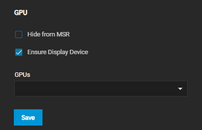
GPU passthrough issues can occur due to the UI passing malformed data to system.advanced.update_gpu_pci_ids resulting in an error dialog on VM creation (NAS-130983).
Users who encounter this issue can simply close the dialog.
The VM should be created with the GPU attached, as expected.
Custom Docker Compose applications deployed via the Custom App button and YAML editor cannot be edited after deployment in 24.10-RC.1 (NAS-131147).
A fix is expected in the 24.10.0 release.
RC.1 users can delete, edit the YAML file, and then redeploy custom applications to make changes.
Custom applications deployed via the Ix-app deployment wizard can be edited in the TrueNAS UI.
Docker applications do not support IPv6 at present (NAS-131333).
A user reports errors restarting the Docker service on system reboot (NAS-131328).
Applications with available updates display an option to view changelogs. These changelogs are not populated at present (NAS-131297).
Application Web UI buttons, accessed from the Application Info widget, can default to a 0.0.0.0:port address after app install or restart (NAS-131308).
Refresh the browser window, or manually access the port in the form hostname or IP address:port, to correct button function and access the app UI.
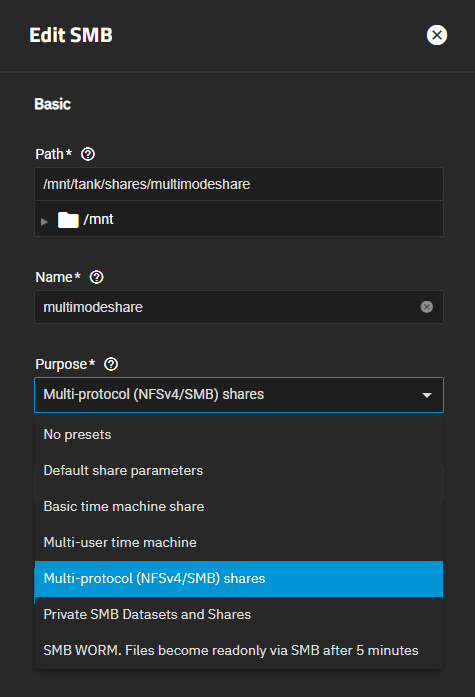
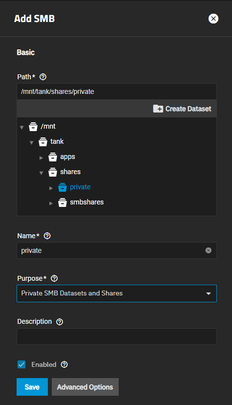
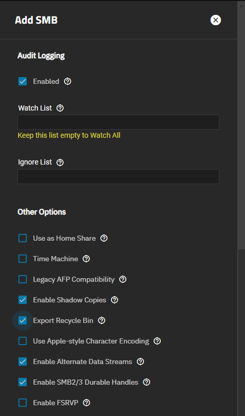
The SMB Share Purpose presets on the Add SMB screen do not adjust advanced options when set (NAS-131374).
Users encountering this issue can manually set the required advanced options.
See Advanced Options Presets in the UI reference guide for more information.
Some users have reported incomplete shutdown and reboot behavior (NAS-130118). This issue has not been reported in iXsystems hardware.
Unexpected behavior can occur when unlocking a dataset with recursive set to false (NAS-130329). Child datasets with inherited keys are also unlocked with the parent dataset.
Development of the new RAIDZ pool expansion feature is ongoing, with fixes for known issues expected in the 24.10.0 release (NAS-131207 and NAS-131028).
Early releases are intended for testing and feedback purposes.
Do not use early-release software for critical tasks.
August 29, 2024
iXsystems is pleased to release TrueNAS 24.10-BETA.1!
This has software component updates and new features that are in the polishing phase.
Notable Changes
Dashboard reworked with more widgets, data reporting, and customization (NAS-127217).
Applications backend framework is shifted from Kubernetes to Docker. See the official announcement for more information. The Custom App installation screen is disabled in 24.10-BETA.1. A redesigned screen, including Docker Compose support, is anticipated for the RC.1 version. See Upgrade Notes for more information.
Preserve SMB alternate data streams when ingesting data from remote servers (NAS-127114).
Rewrite TrueNAS installer to better support future development efforts (NAS-127092).
The Allow root login option is removed from the FTP service (NAS-128837).
Implement a globally unique system ID (NAS-123519).
Remove creation/reporting/management of swap on TrueNAS (NAS-12887).
Rename the default administrator account (UID 950) from admin to truenas_admin to prevent DS conflicts (NAS-129997).
This change affects fresh installs of 24.10 only.
Existing admin accounts are preserved on upgrade.
For improved security, we recommended that users create a unique administrator account and disable password access for default administrator accounts.
See Using Administrator Logins for more information.
SMB audit log entries are omitted by default from the System > Audit screen (NAS-130498).
To view SMB audit results, go to System > Services and click receipt_longAudit Logs for the SMB service or use advanced search on the main Audit screen to query SMB events.
To switch between detail and list views for the changelog, press t.
Open the changelog in Jira to see the Export menu to print or download the changelog in various file formats.
Known Issues
The System > Audit screen can display different values for Timestamp in the entries list and Localtime in Event Data, depending on the local timezone of the system (NAS-130373).
Some users have reported incomplete shutdown and reboot behavior (NAS-130118). This issue has not been reported in iXsystems hardware.
Unexpected behavior can occur when unlocking a dataset with recursive set to false (NAS-130329). Child datasets with inherited keys are also unlocked with the parent dataset.
Development of the new TrueCloud backup feature for TrueNAS and Storj integration is ongoing, with fixes for known issues expected in a future 24.10 development version release (NAS-130320, NAS-130794, and NAS-130644).
Auto-populated portal group IDs for iSCSI configurations can differ between the Portals and Targets screen. This is a cosmetic issue in the UI and underlying functionality is not impacted (NAS-130656).
Audit logging status indicators on SMB share tables might not accurately reflect if logging is or is not enabled on a given share (NAS-130830).
App icons can periodically fail to render on the Discover applications screen, especially when searching for applications (NAS-130831).
On the virtual machine creation screen, a validation error displays if a configured GPU device is not valid for use in the VM. However, in some cases it can be possible to continue and create the VM with an invalid GPU configuration (NAS-130754). If you receive a GPU validation error during VM creation, remove or correct the invalid GPU before creating the VM.
From repurposed systems to highly custom builds, the fundamental freedom of TrueNAS is the ability to run it on almost any x86 computer.
Minimum Hardware Requirements
Processor
Memory
Boot Device
Storage
2-Core Intel 64-Bit or AMD x86_64 processor
8 GB memory
16 GB SSD boot device
Two identically-sized devices for a single storage pool
The TrueNAS installer recommends 8 GB of RAM.
TrueNAS installs, runs, and operates jails (in TrueNAS 13).
It also hosts SMB shares and replicates TBs of data with less. iXsystems recommends the above for better performance and fewer issues.
You do not need an SSD boot device, but we discourage using a spinner or a USB stick.
We do not recommend installing TrueNAS on a single disk or striped pool unless you have a good reason to do so.
You can install and run TrueNAS without any data devices, but we strongly discourage it.
TrueNAS does not require two cores, as most halfway-modern 64-bit CPUs likely already have at least two.
For help building a system according to your unique performance, storage, and networking requirements, keep reading.
Storage Considerations
The heart of any storage system is the symbiotic pairing of the file system and physical storage devices.
The ZFS file system in TrueNAS provides the best available data protection of any file system at any cost and makes effective use of both spinning-disk and all-flash storage or a mix of the two.
ZFS is prepared for the eventual failure of storage devices and is highly configurable to achieve the perfect balance of redundancy and performance to meet any storage goal.
A properly configured TrueNAS system can tolerate multiple storage device failures and recreate its boot media with a copy of the configuration file.
Storage Device Quantities
TrueNAS can manage many storage devices as part of a single storage array.
With more enterprise-level tuning in the mature 13.0 release and similar tuning in the upcoming SCALE Cobia release, TrueNAS can manage as many as 1,250 drives in a single storage array!
Storage Media
Choosing storage media is the first step in designing the storage system to meet immediate objectives and prepare for future capacity expansion.
Spinning Disks
Until the next scientific breakthrough in storage media, spinning hard disks are here to stay thanks to their balance of capacity and cost.
The arrival of double-digit terabyte consumer and enterprise drives provides more choices to TrueNAS users than ever.
TrueNAS Mini systems ship with Western Digital NAS and NL-SAS by default. Understanding the alternatives explains why.SATA NAS Disks
Serial Advanced Technology Attachment (SATA) is still the de facto standard disk interface found in many desktop/laptop computers, servers, and some non-enterprise storage arrays.
The first SATA disks offered double-digit gigabyte capacities. Newer SATA disks meet many size, reliability, and performance goals.
While consumer desktop SATA disks do not have the overall reliability issues they once had, they are still not designed or warrantied for continuous operation or use in RAID groups.
Enterprise SATA disks address the always-on factor, vibration tolerance, and drive error handling required in storage systems.
However, the price gap between desktop and enterprise SATA drives is so vast that many users push their consumer drives into 24/7 service pursuing cost savings.
Drive vendors, likely tired of honoring warranties for failed desktop drives used in incorrect applications, responded to this gap in the market by producing NAS drives.
NAS drives achieved fame from the original Western Digital (WD) Red™ drives with Conventional Magnetic Recording (CMR) technology (now called WD Red Plus).
Western Digital designed the WD Red™ Plus NAS drives (non-SMR) for systems with up to 8 hard drives, the WD Red™ Pro for systems with up to 16 drives, and the WD UltraStar™ for systems beyond 16 drives.
The iXsystems Community Forum prefers WD drives for TrueNAS builds due to their exceptional quality and reliability.
All TrueNAS Minis ship with WD Red™ Plus drives unless requested otherwise.
Consult your drive manufacturer, such as Western Digital or Seagate, to determine whether a disk uses CMR or SMR technology.
Nearline SAS Disks
Nearline SAS (NL-SAS) disks are 7200 RPM enterprise SATA disks with the industry-standard SAS interface in most enterprise storage systems.
SAS stands for serial attached SCSI, with the traditional SCSI disk interface in serial form.
SAS systems, designed for data center storage applications, have accurate, verbose error handling, predictable failure behavior, reliable hot swapping, and the added feature of multipath support.
Multipath access means that each drive has two interfaces and can connect to two storage controllers or one controller over two cables.
This redundancy protects against cable, controller card, or complete system failure in the case of the TrueNAS high-availability architecture in which each controller is an independent server that accesses the same set of NL-SAS drives.
NL-SAS drives are also robust enough to handle the rigors of systems with more than 16 disks.
So, capacity-oriented TrueNAS systems ship with Western Digital UltraStar NL-SAS disks thanks to the all-around perfect balance of capacity, reliability, performance, and flexibility that NL-SAS drives offer.SAS Disks
Enterprise SAS disks, built for the maximum performance and reliability that a spinning platter can provide, are the traditional heavy-lifters of the enterprise storage industry.
SAS disk capacities are low compared to NL-SAS or NAS drives due to the speed at which the platters spin, reaching as high as 15,000 RPMs.
While SAS drives might sound like the ultimate answer for high-performance storage, many consumer and enterprise flash-based options have come onto the market and significantly reduced the competitiveness of SAS drives.
For example, we almost completely replaced enterprise SAS drives discontinued from the TrueNAS product lines with flash drives (SSDs or NVMe) in 2016 due to their superior performance/cost ratio.SATA & SAS Flash Storage SSDs
Flash storage technology has progressed significantly in recent years, leading to a revolution in mobile devices and the rise of flash storage in general-purpose PCs and servers.
Unlike hard disks, flash storage is not sensitive to vibration and can be much faster with comparable reliability.
Flash storage remains more expensive per GB, but is becoming more common in TrueNAS systems as the price gap narrows.
The shortest path for introducing flash storage into the mainstream market was for vendors to use standard SATA/SAS hard disk interfaces and form factors that emulate standard hard disks without moving parts.
For this reason, flash storage Solid State Disks (SSDs) have SATA interfaces and are the size of 2.5" laptop hard disks, allowing using them as drop-in replacements for traditional hard disks.
Flash storage SSDs can replace HDDs for primary storage on a TrueNAS system, resulting in a faster, albeit smaller or more expensive storage solution.
If you plan to go all-flash, buy the highest-quality flash storage SSDs your budget allows, focusing on power, safety, and write endurance that matches your expected write workload.
NVMe
While SSDs pretending to be HDDs made sense for rapid adoption, the Non-Volatile Memory Express (NVMe) standard is a native flash protocol that takes full advantage of the flash storage non-linear, parallel nature.
The main advantage of NVMe is low-latency performance. NVMe is becoming a mainstream option for boot and other tasks.
At first, NVMe only came in expansion-card form factors such as PCIe and M.2.
The new U.2 interface offers a universal solution that includes the 2.5" drive form factor and an externally accessible (but generally not hot-swappable) NVMe interface.
NVMe devices can run quite hot and might need dedicated heat sinks.
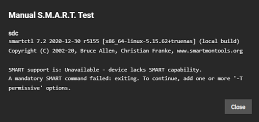
Manual S.M.A.R.T. tests on NVMe devices are currently not supported.
USB Hard Disks
Avoid using USB-connected hard disks for primary storage with TrueNAS. You can use USB Hard Disks for very basic backups in a pinch.
While TrueNAS does not automate this process, you can connect a USB HDD, replicate at the command line, and then take it off-site for safekeeping.
Warning: USB-connected media (including SSDs) might report their serial numbers inaccurately, making them indistinguishable.
These storage device media arrange together to create powerful storage solutions.
Storage Solutions
Hybrid Storage & Flash Cache (SLOG/ZIL/L2ARC)
With hard disks providing double-digit terabyte capacities and flash-based options providing even higher performance, a best-of-both-worlds option is available.
With TrueNAS and OpenZFS, you can merge flash and disk to create hybrid storage that makes the most of both types.
Hybrid setups use high-capacity spinning disks to store data, while DRAM and flash perform hyper-fast read and write caching.
The technologies work together with a flash-based separate write log (SLOG). Think of it as a write cache keeping the ZFS-intent log (ZIL) that speeds up writes.
On the read side, flash is a level two adaptive replacement (read) cache (L2ARC) to keep the hottest data sets on the faster flash media.
Workloads with synchronous writes, such as NFS and databases, benefit from SLOG devices, while workloads with frequently-accessed data might benefit from an L2ARC device.
An L2ARC device is not always the best choice because the level one ARC in RAM always provides a faster cache, and the L2ARC table uses some RAM.
SLOG devices do not need a large capacity since they only need to service five seconds of data writes delivered by the network or a local application.
A high-endurance, low-latency device between 8 GB and 32 GB is adequate for most modern networks, and you can strip or mirror several devices for either performance or redundancy.
Pay attention to the published endurance claims for the device since a SLOG acts as the funnel point for most of the writes made to the system.
SLOG devices also need power protection.
The purpose of the ZFS intent log (ZIL), and thus the SLOG, is to keep sync writes safe during a crash or power failure.
If the SLOG is not power-protected and loses data after a power failure, it defeats the purpose of using a SLOG in the first place.
Check the manufacturer specifications for the device to ensure the SLOG device is power-safe or has power loss/failure protection.
The most important quality to look for in an L2ARC device is random read performance.
The device must support more IOPS than the primary storage media it caches.
For example, using a single SSD as an L2ARC is ineffective in front of a pool of 40 SSDs, as the 40 SSDs can handle far more IOPS than the single L2ARC drive.
As for capacity, 5x to 20x more than the RAM size is a good guideline.
High-end TrueNAS systems can have NVMe-based L2ARC in double-digit terabyte sizes.
Remember that for every data block in the L2ARC, the primary ARC needs an 88-byte entry.
Poorly-designed systems can cause an unexpected fill-up in the ARC and reduce performance.
For example, a 480 GB L2ARC filled with 4KiB blocks needs more than 10GiB of metadata storage in the primary ARC.
Self Encrypting Drives
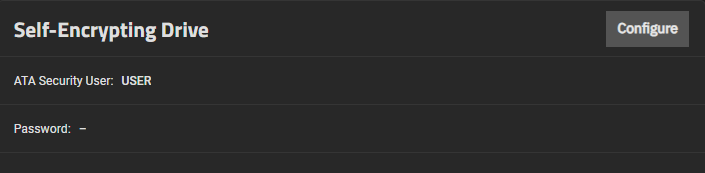
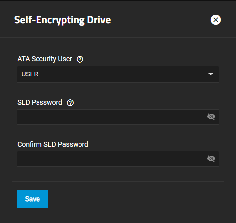
TrueNAS supports two forms of data encryption at rest to achieve privacy and compliance objectives: native ZFS encryption and self-encrypting drives (SEDs).
SEDs do not experience the performance overhead introduced by software partition encryption but are not as readily available as non-SED drives (and thus can cost a little more).Boot Devices
Booting legacy FreeNAS systems from 8 GB or larger USB flash drives was once very popular.
We recommend looking at other options since USB drive quality varies widely, and modern TrueNAS versions perform increased drive writes to the boot pool.
For this reason, all pre-built TrueNAS Systems ship with either M.2 drives or SATA DOMs.
SATA DOMs, or disk-on-modules, offer reliability close to consumer 2.5" SSDs with a smaller form factor that mounts to an internal SATA port and does not use a drive bay.
Because SATA DOMs and motherboards with M.2 slots are not as common as the other storage devices mentioned here, users often boot TrueNAS systems from 2.5" SSDs and HDDs (often mirrored for added redundancy).
The recommended size for the TrueNAS boot volume is 8 GB, but 16 or 32 GB (or a 120 GB 2.5" SATA SSD) provides room for more boot environments.
Hot Swapability
TrueNAS systems come in all shapes and sizes.
Many users want external access to all storage devices for efficient replacement if issues occur.
Most hot-swap drive bays need a proprietary drive tray into which you install each drive.
These bay and tray combinations often include convenient features like activity and identification lights to visualize activity and illuminate a failed drive with sesutil(8) for CORE or for SCALE.
TrueNAS Mini systems ship with four or more hot-swap bays.
TrueNAS R-Series systems can support dozens of drives in their head units and external expansion shelves.
Pre-owned or repurposed hardware is popular among TrueNAS users. Pay attention to the maximum performance offered by the hot-swap backplanes of a given system.
Aim for at least 6 Gbps SATA III support.
Note that hot-swapping PCIe NVMe devices is not currently supported.
Pool layout (the organization of LUNs and volumes, in TrueNAS/ZFS parlance) is outside of the scope of this guide.
The availability of double-digit terabyte drives raises a question TrueNAS users now have the luxury of asking: How many should I use to achieve my desired capacity?
You can mirror two 16 TB drives to achieve 16 TB of available capacity, but that does not mean you should.
Mirroring two large drives offers the advantage of redundancy and balancing reads between the two devices, which could lower power draw, but little else.
The write performance of two large drives is similar to that of a single drive.
By contrast, an array of eight 4 TB drives offers a wide range of configurations to optimize performance and redundancy at a lower cost.
If configured as striped mirrors, eight drives can yield four times greater write performance with a similar total capacity.
You might also consider adding a hot-spare drive with any pool configuration, which lets the pool automatically rebuild itself if one of its primary drives fails.
Storage Device Burn-In
Spinning disk hard drives have moving parts that are highly sensitive to shock and vibration and wear out with use.
Consider pre-flighting every storage device before putting it into production, especially:
Start a long HDD self-test (smartctl -t long /dev/). After the test completes (could take 12+ hrs):
Check the results (smartctl -a /dev/)
Check pending sector reallocations (smartctl -a /dev/ | grep Current_Pending_Sector)
Check reallocated sector count (smartctl -a /dev/ | grep Reallocated_Sector_Ct)
Check the UDMA CRC errors (smartctl -a /dev/ | grep UDMA_CRC_Error_Count)
Check HDD and SSD write latency consistency (diskinfo -wS for CORE or iostat or fio for SCALE systems) Unformatted drives only!
Check HDD and SSD hours (smartctl -a /dev/ | grep Power_On_Hours)
Take time to create a pool before deploying the system.
Subject it to as close to a real-world workload as possible to reveal individual drive issues and help determine if an alternative pool layout is better suited to that workload.
Be cautious of used drives, as vendors might not be honest or informed about their age and health.
Verify vendors have not recertified drives by checking the hours using smartctl(8) for all new drives.
A drive vendor might also zero the hours of a drive during recertification, masking the drive age.
iXsystems tests all storage devices it sells for at least 48 hours before shipment.
Storage Controllers
The uncontested most popular storage controllers used with TrueNAS are the 6 and 12 Gbps (Gigabits per second, sometimes expressed as Gb/s) Broadcom (formerly Avago, formerly LSI) SAS host bus adapters (HBA).
Controllers ship embedded on some motherboards but are generally PCIe cards with four or more internal or external SATA/SAS ports.
The 6 Gbps LSI 9211 and rebranded siblings with the LSI SAS2008 chip, such as the IBM M1015 and Dell H200, are legendary among TrueNAS users who build systems using parts from the second-hand market.
Flash using the latest IT or Target Mode firmware to disable the optional RAID functionality found in the IR firmware on Broadcom controllers.
For those with the budget, newer models like the Broadcom 9300/9400 series give 12 Gbps SAS capabilities and even NVMe to SAS translation abilities with the 9400 series.
TrueNAS includes the sas2flash, sas3flash, and storcli commands to flash or perform re-flashing operations on 9200, 9300, and 9400 series cards.
Onboard SATA controllers are popular with smaller builds, but motherboard vendors are better at catering to the needs of NAS users by including more than the traditional four SATA interfaces.
Be aware that many motherboards ship with a mix of 3 Gbps and 6 Gbps onboard SATA interfaces and that choosing the wrong one can impact performance.
If a motherboard includes hardware RAID functionality, do not use or configure it, but note that disabling it in the BIOS might remove some SATA functionality, depending on the motherboard.
Most SATA compatibility-related issues are immediately apparent.
There are countless warnings against using hardware RAID cards with TrueNAS.
ZFS and TrueNAS provide a built-in RAID that protects your data better than any hardware RAID card.
You can use a hardware RAID card if it is all you have, but there are limitations.
First and most importantly, do not use their RAID facility if your hardware RAID card supports HBA mode, also known as passthrough or JBOD mode (there is one caveat in the bullet list below). When used, it allows it to perform indistinguishably from a standard HBA.
If your RAID card does not have this mode, you can configure a RAID0 for every disk in your system.
While not the ideal setup, it works in a pinch.
If repurposing hardware RAID cards with TrueNAS, be aware that some hardware RAID cards can:
Mask disk serial number and S.M.A.R.T. health information
Perform slower than their HBA equivalents
Cause data loss if using a write cache with a dead battery backup unit (BBU)
SAS Expanders
A direct-attached system, where every disk connects to an interface on the controller card, is optimal but not always possible.
A SAS expander (a port multiplier or splitter) enables each SAS port on a controller card to service many disks.
You find SAS expanders only on the drive backplane of servers or JBODs with more than twelve drive bays.
For example, a TrueNAS JBOD that eclipses 90 drives in only four rack units of space is not possible without SAS expanders.
Imagine how many eight-port HBAs you need to access 90 drives without SAS expanders.
While SAS expanders, designed for SAS disks, can often support SATA disks via the SATA Tunneling Protocol or STP, we still prefer SAS disks for reasons mentioned above in the NL-SAS section (SATA disks function on a SAS-based backplane).
Remember that you cannot use a SAS drive in a port designed for SATA drives.
Storage Device Cooling
A much-cited study floating around the Internet asserts that drive temperature has little impact on drive reliability.
The study makes for a great headline or conversation starter, but carefully reading the report indicates that they tested the drives under optimal environmental conditions.
The average temperature that a well-cooled spinning hard disk reaches in production is around 28 °C, and one study found that disks experience twice the number of failures for every 12 °C increase in temperature.
Before adding drive cooling that often comes with added noise (especially on older systems), know that you risk throwing money away by running a server in a data center or closet without noticing that the internal cooling fans are at their lowest setting.
Pay close attention to drive temperature in any chassis that supports 16 or more drives, especially if they are exotic, high-density designs.
Every chassis has certain areas that are warmer for whatever reason. Watch for fan failures and the tendency for some models of 8 TB drives to run hotter than other drive capacities.
In general, try to keep drive temperatures below the drive specification provided by the vendor.
Memory, CPU, and Network Considerations
Memory Sizing
TrueNAS has higher memory requirements than many Network Attached Storage solutions for good reason: it shares dynamic random-access memory (DRAM or simply RAM) between sharing services, add-on plugins and/or jails (in CORE) or apps (in SCALE), virtual machines, and sophisticated read caching.
RAM rarely goes unused on a TrueNAS system, and enough RAM is vital to maintaining peak performance.
You should have 8 GB of RAM for basic TrueNAS operations with up to eight drives. Other use cases each have distinct RAM requirements:
Add 1 GB for each drive added after eight to benefit most use cases.
Add extra RAM (in general) if more clients connect to the TrueNAS system.
A 20 TB pool backing many high-performance VMs over iSCSI might need more RAM than a 200 TB pool storing archival data.
If using iSCSI to back up VMs, plan to use at least 16 GB of RAM for good performance and 32 GB or more for optimal performance.
Add 2 GB of RAM for directory services for the Winbind internal cache.
Add more RAM for plugins and jails, as each has specific application RAM requirements.
Add more RAM for virtual machines with a guest operating system and application RAM requirements.
Add the suggested 5 GB per TB of storage for deduplication that depends on an in-RAM deduplication table.
Add approximately 1 GB of RAM (conservative estimate) for every 50 GB of L2ARC in your pool.
Attaching an L2ARC drive to a pool uses some RAM, too. ZFS needs metadata in ARC to know what data is in L2ARC.
Error Correcting Code Memory
Electrical or magnetic interference inside a computer system can cause a spontaneous flip of a single bit of RAM to the opposite state, resulting in a memory error.
Memory errors can cause security vulnerabilities, crashes, transcription errors, lost transactions, and corrupted or lost data.
So RAM, the temporary data storage location, is one of the most vital areas for preventing data loss.
Error-correcting code or ECC RAM detects and corrects in-memory bit errors as they occur.
If errors are severe enough to be uncorrectable, ECC memory causes the system to hang (become unresponsive) rather than continue with errored bits.
For ZFS and TrueNAS, this behavior virtually eliminates any chances that RAM errors pass to the drives to cause corruption of the ZFS pools or file errors.
To summarize the lengthy, Internet-wide debate on whether to use error-correcting code (ECC) system memory with OpenZFS and TrueNAS, most users strongly recommend ECC RAM as another data integrity defense. However:
Some CPUs or motherboards support ECC RAM but not all
Many TrueNAS systems operate every day without ECC RAM
RAM of any type or grade can fail and cause data loss
RAM failures usually occur in the first three months, so test all RAM before deployment.
Central Processing Unit (CPU) Selection
Choosing ECC RAM limits your CPU and motherboard options, but that can be beneficial.
Intel® limits ECC RAM support to workstation and server motherboards.
The 13th generation of their consumer CPUs, such as the Core i5 and i7, support ECC as long as they are paired with a workstation motherboard chipset, such as the W680.
Refer to Intel ARK for a full list of Intel CPUs with ECC support.
Which CPU to choose can come down to a short list of factors:
An underpowered CPU can create a performance bottleneck because of how OpenZFS compresses and encrypts (optional) data and performs checksums.
A higher-frequency CPU with fewer cores usually performs best for SMB-only workloads because of Samba, the lightly-threaded TrueNAS SMB daemon.
A higher-core-count CPU is better suited for parallel encryption and virtualization.
A CPU with AES-NI encryption acceleration support improves the speed of the file system and network encryption.
A server-class CPU is recommended for power and ECC memory support.
A Xeon E5 CPU (or similar) is recommended for software-encrypted pools.
An Intel Ivy Bridge CPU or later is recommended for virtual machine use.
Watch for VT-d/AMD-Vi device virtualization support on the CPU and motherboard to pass PCIe devices to virtual machines.
Be aware if a given CPU contains a GPU or requires an external one. Also note that many server motherboards include a BMC chip with a built-in GPU. See below for more details on BMCs.
AMD CPUs are becoming more popular thanks to the Ryzen and EPYC (Naples/Rome) lines.
Support for these platforms is limited on FreeBSD and, by extension, TrueNAS 13. However, Linux has more support, and TrueNAS 24.10 should work with AMD CPUs without issue.
SHA Extensions for x86 instruction set architecture
SHA Extensions in the x86 instruction set architecture support Secure Hash Algorithm family hardware acceleration.
Intel Goldmont (and later), Ice Lake (and later), and Rocket Lake (and later), as well as AMD Zen (and later) processors support the SHA instruction set.
Remote Management: IPMI
As a courtesy to further limit the motherboard choices, consider the Intelligent Platform Management Interface or IPMI (a.k.a. baseboard management controller, BMC, iLo, iDrac, and other names depending on the vendor) if you need:
Remote power control and monitoring of remote systems
Remote console shell access for configuration or data recovery
Remote virtual media for TrueNAS installation or reinstallation
TrueNAS relies on its web-based user interface (UI), but you might occasionally need console access to make network configuration changes.
TrueNAS administration and sharing use a single network interface by default, which can be challenging when you upgrade features like LACP aggregated networking.
The ideal solution is to have a dedicated subnet to access the TrueNAS web UI, but not all users have this luxury.
The occasional visit to the hardware console is necessary for global configuration and system recovery.
The latest TrueNAS Mini and R-Series systems ship with full-featured, HTML5-based IPMI support on a dedicated gigabit network interface.
Power Supply Units
The top criteria to consider for a power supply unit (or PSU) on a TrueNAS system are:
Power capacity (in watts) for the motherboard and the number of drives it must support
Reliability
Efficiency rating
Relative noise
Optional redundancy to keep critical systems running if one power supply fails
Select a PSU rated for the initial and a future load placed on it.
Have a PSU with adequate power to migrate from a large-capacity chassis to a fully-populated chassis.
Also, consider a hot-swappable redundant PSU to help guarantee uptime.
Users on a budget can keep a cold spare PSU to limit their potential downtime to hours rather than days.
A good, modern PSU is efficient and integrates into the IPMI management system to provide real-time fan, temperature, and load information.
Most power supplies carry a certified efficiency rating known as an 80 Plus rating.
The 80 plus rating indicates the PSU loses the power drawn from the wall as heat, noise, and vibration instead of powering your components.
If a power supply needs to draw 600 watts from the wall to provide 500 watts of power to your components, it operates at 500/600 = ~83% efficiency.
The other 100 watts get lost as heat, noise, and vibration.
Power supplies with higher ratings are more efficient but also far more expensive.
Do some return-on-investment calculations if you are unsure what efficiency to buy.
For example, if an 80 Plus Platinum PSU costs $50 more than the comparable 80 Plus Gold, it should save you at least $10 per year on your power bill for that investment to pay off over five years.
You can read more about 80 Plus ratings in this post.
Uninterruptible Power Supplies
TrueNAS allows the system to communicate with a battery-backed, uninterruptible power supply (UPS) over a traditional serial or USB connection to coordinate a graceful shutdown in the case of power loss.
TrueNAS works well with APC brand UPS, followed by CyberPower. Consider budgeting for a UPS with pure sine wave output.
Some models of SSD can experience data corruption on power loss.
If several SSDs experience simultaneous power loss, it could cause total pool failure, making a UPS a critical investment.
Ethernet Networking
The network in Network Attached Storage is as important as storage, but the topic has a few key points:
Simplicity - Simplicity is often the secret to reliability with network configurations.
Individual interfaces - Faster individual interfaces such as 10/25/40/100GbE are preferable to aggregating slower interfaces.
Interface support - Intel and Chelsio interfaces are the best-supported options.
Packet fragmentation - Only consider jumbo framesMTU with dedicated connections, such as between servers or video editors and TrueNAS that are unlikely to experience packet fragmentation.
LRO/LSO offload features - Interfaces with LRO and LSO offload features generally alleviates the need for jumbo frames, and their use can result in lower CPU overhead.
High-Speed Interconnects
Higher-band hardware is becoming more accessible as the hardware development pace increases and enterprises upgrade more quickly.
Home labs can now deploy and use 40 GB and higher networking components. Home users are now discovering the same issues and problems with these higher speeds found by Enterprise customers.
iXsystems recommends using optical fiber over direct attached copper (DAC) cables for the high-speed interconnects listed below:
10Gb NICs: SFP+ connectors
25Gb NICs: SFP28 connectors
40Gb NICs: QSFP+ connectors
100Gb NICs: QSFP28 connectors
200Gb NICs: QSFP56 connectors
400Gb NICs: QSFP-DD connectors
iXsystems also recommends using optical fiber for any transceiver form factors mentioned when using fiber channels.
Direct attached copper (DAC) cables can create interoperability issues between the NIC, cable, and switch.
Virtualized TrueNAS
Finally, the ultimate TrueNAS hardware question is whether to use actual hardware or choose a virtualization solution.
At the heart of the TrueNAS design is OpenZFS. OpenZFS works best with physical storage devices. It is aware of their strengths and compensates for their weaknesses.
TrueNAS developers virtualize TrueNAS every day as part of their work, and it is intended only for use as a development environment.
While you can deploy TrueNAS in a virtual environment, we do not recommend doing so for regular deployment of TrueNAS when storing production or critical data.
Virtualizing TrueNAS and using virtual disks for your pool is fine for ad hoc proof-of-concept, but it is not a supported configuration and might result in data corruption.
When the need arises to virtualize TrueNAS (for ad hoc proof-of-concept):
Pass hardware disks or the entire storage controller to the TrueNAS VM if possible (requires VT-d/AMD-Vi support).
Disable automatic scrub pools on virtualized storage such as VMFS, and never scrub a pool while running storage repair tasks on another layer.
Use at least three vdevs to provide adequate metadata redundancy, even with a striped pool.
Provide one or more 8 GB or larger boot devices.
Provide the TrueNAS VM with adequate RAM per its usual requirements.
Consider jumbo frame networking if all devices support it.
Understand that the guest tools in FreeBSD might lack features other guest operating systems have.
Enable MAC address spoofing on virtual interfaces and enable promiscuous mode to use VNET jail and plugins.
Installation Instructions
This section provides instructions for users that are installing TrueNAS SCALE the first time on their own system hardware and for users that need to do a clean install of SCALE.
TrueNAS Enterprise
TrueNAS SCALE Enterprise customers should contact iXsystems Support for assistance with the initial set up and configuration of their systems.
Contacting iX Support
Customers who purchase iXsystems hardware or that want additional support must have a support contract to use iXsystems Support Services. The TrueNAS Community forums provides free support for users without an iXsystems Support contract.
The installation process covers installing SCALE using an iso.
TrueNAS SCALE uses DHCP to provide the initial system IP address.
After that, either use the Console setup menu to reconfigure the primary network interface with a static IP address or use the SCALE UI to make network changes and complete the initial configuration.
Finally, it covers backing up your system configuration to a file and saving an initial system debug file.
Installing SCALE: Provides the SCALE iso file installation instructions for physical hardware and virtual machines. Describes the iso verification process using an OpenPGP encryption application.
Installing SCALE Enterprise (HA): Provides a sequential process to complete the installation of a SCALE Enterprise (HA) dual controller NAS system using an iso file and the SCALE UI.
Using the Console Setup Menu: Provides information on using the Console Setup menu after installing TrueNAS SCALE from the iso file to configure network settings.
Preparing for SCALE UI Configuration
SCALE users installing and configuring SCALE on their own servers should use the information in this article to prepare for their SCALE system deployments.
For SCALE support or assistance refer to the TrueNAS community forums, Discord, or the tutorials included in the TrueNAS Documentation Hub.
If you are not the administrator responsible for network access in your company, contact your network administrator for assistance.
If your company obtains network hardware and support from an Internet or cable service provider, contact them for assistance with where to obtain this information.
Physical Access
When in the same location as the hardware designated for the TrueNAS installation, you can connect a monitor and keyboard to the system to do the initial installation and configuration.
An additional USB port is required when using a USB storage device to install TrueNAS from an .iso file.
IPMI Access
Intelligent Platform Management Interface (IPMI) servers provide access to servers and allow remote users to install software and configure or administrate systems at the console level, or as though you are in the room with the server when you are working remotely. Ensure IPMI is properly configured for secure remote management of TrueNAS servers.
To provide for remote administration of your TrueNAS SCALE system, assign access through an IPMI server to the TrueNAS server.
To make this possible assign an IP address to use for access and set up administrator credentials (user name and password) to access the TrueNAS IPMI connections.
Network Access
TrueNAS uses DHCP to assign the IP address to the primary system network interface. DHCP only provisions one IP address.
You can use this DHCP-provided address, or you can assign a static IP address.
You must assign an IP address to each network interface card (NIC) installed in your system if you want to communicate over your network using the interfaces.
To configure your TrueNAS server to work with your network, you need:
DHCP broadcast messages enabled on the network or the subnet(s) in your network where TrueNAS is installed.
DNS name sever IP addresses in your network (SCALE can accommodate up to three name server IP addresses).
IP address for the Network Time Protocol (NTP) server you use to synchronize time across your servers and network.
Main domain name or the domain name for the portion of your network where the TrueNAS SCALE server is deployed.
Host name you want to use if not using the default-assigned host name in SCALE (truenas is the default host name in SCALE).
IP address for each additional network interface added in your system and connected to your network (static IP not provided by DHCP).
IP address assigned to the controller.
Either allow DHCP to assign the IP address or assign a static IP.
If you obtained network equipment and Internet service access from either an Internet or cable service provider, contact their support departments for assistance with network addresses.
SMTP Access
Simple Mail Transfer Protocol (SMTP) service or servers allow for the transfer of electronic mail across an Internet connection.
TrueNAS uses either SMTP to send mail from SCALE to administrator or designated individual email addresses for system alert notifications.
If you do not know this information and do not have a network administrator in your company, or if you are a home user, contact your Internet or cable service provider to obtain the SMTP addresses to allow TrueNAS to send emails from your network.
Directory Service Access
This section does not apply to small companies with very few users or home deployments of SCALE.
TrueNAS SCALE works with either Active Directory or LDAP directory servers, and it can also work with Kerberos and IDmap.
Active Directory and LDAP configuration settings have similar requirements.
Active Directory
Provide the following information to configure SCALE Active Directory access:
Domain name for where the Active Directory server is located
Authentication credentials for access to the Active Directory server (admin user name and password to allow SCALE to communicate with the server)
List of trusted domains SCALE should allow
LDAP
Provide the following information to configure SCALE LDAP access:
Host name where the LDAP sever is located and where SCALE accesses it
Base and bind distinguished names (DN) and the bind password which are the authentication credentials
Kerberos realm and keytab information if used in your directory server deployment for SCALE to use for authentication
Advanced Directory Services
When configuring Kerberos and/or IDmap, you might need to provide:
Kerberos realm and keytab information
IDmap schema information
Preparing for SCALE UI Configuration (Enterprise)
TrueNAS Enterprise
SCALE Enterprise customers, or those that purchased systems and service contracts from iXsystems, should use the information in this article to prepare for their SCALE system deployments.
The iXsystems Support department provides assistance with the configuration areas documented in this section.
Contacting Support
Customers who purchase iXsystems hardware or that want additional support must have a support contract to use iXsystems Support Services. The TrueNAS Community forums provides free support for users without an iXsystems Support contract.
Because there are many possible scenarios for network configurations, this section covers the basics of the access and information required to configure SCALE to work in your network environment.
If you are the individual tasked with installing and configuring the TrueNAS SCALE server but are not responsible for network services in your company, contact your network administrator to request they provision and verify new IP address assignments and provide the other information for access.
Physical Access
When in the same location as the hardware designated for the TrueNAS installation, you can connect a monitor and keyboard to the system to do the initial installation and configuration.
An additional USB port is required when using a USB storage device to install TrueNAS from an .iso file.
IPMI Access
The Intelligent Platform Management Interface (IPMI) provides a way for system administrators to remotely access their TrueNAS system.
Through this remote access, administrators can install software, and configure or administer systems at the console level as though they are in the room with the server.
TrueNAS Enterprise systems sold by iXsystems provide IPMI network ports, but other hardware might not have IPMI ports.
iXsystems requires access through your IPMI server to access the TrueNAS server to provide remote administration support.
To make this possible:
Assign an IP address to the IPMI port of each controller in the TrueNAS array.
If you have a High Availability (HA) system, the server is equipped with two controllers so assign two IP addresses, one for each controller.
Create and provide administrator credentials (user name and password) for access to the TrueNAS IPMI connections.
Configure the administrator credentials to access both IP addresses assigned to the HA system controllers.
Network Access
TrueNAS uses DHCP to assign the IP address to the primary system network interface. DHCP only provisions one IP address.
You can use this DHCP-provided address, or you can assign a static IP address.
You must assign an IP address to each network interface card (NIC) installed in your system if you want to communicate over your network using the interfaces.
To configure your TrueNAS server to work with your network, you need:
DHCP broadcast messages enabled on the network or the subnet(s) in your network where TrueNAS is installed.
DNS name sever IP addresses in your network (SCALE can accommodate up to three name server IP addresses).
IP address for the Network Time Protocol (NTP) server you use to synchronize time across your servers and network.
Main domain name or the domain name for the portion of your network where the TrueNAS SCALE server is deployed.
Host name you want to use if not using the default-assigned host name in SCALE (truenas is the default host name in SCALE).
IP address for each additional network interface added in your system and connected to your network (static IP not provided by DHCP).
IP address assigned to the controller.
Either allow DHCP to assign the IP address or assign a static IP.
If you have an HA system with two controllers, you must assign a total of three IP addresses:
A virtual IP for access to the UI when either controller is active
An IP address for the primary network port on controller A
An IP address for the primary network port on controller B
iXsystems Support can assist you with any questions you have with these network requirements.
Provide the information listed to iXsystems when requested to expedite configuring your system network settings.
The failover feature on TrueNAS Enterprise platforms with High Availability (HA) can malfunction in network environments that heavily use the Spanning Tree Protocol (STP).
When configuring or troubleshooting HA failover, if TrueNAS HA failover does not function properly, investigate STP use in the network and consider disabling STP on network switch ports connected to the TrueNAS platform.
SMTP Access
Simple Mail Transfer Protocol (SMTP) service or servers allow for the transfer of electronic mail across an Internet connection.
TrueNAS uses either SMTP to send mail from SCALE to administrator or designated individual email addresses for system alert notifications.
Have your network administrators provide the SMTP addresses to allow TrueNAS to send emails from your network.
Directory Service Access
TrueNAS SCALE works with either Active Directory or LDAP directory servers, and it can also work with Kerberos and IDmap.
Active Directory and LDAP configuration settings have similar requirements.
Additionally, consider implementing two-factor authentication (2FA) for enhanced security when authenticating users against Active Directory or LDAP directory servers.
Active Directory
Provide the following information to configure SCALE Active Directory access:
Domain name for where the Active Directory server is located
Authentication credentials for access to the Active Directory server (admin user name and password to allow SCALE to communicate with the server)
List of trusted domains SCALE should allow
LDAP
Provide the following information to configure SCALE LDAP access:
Host name where the LDAP sever is located and where SCALE accesses it
Base and bind distinguished names (DN) and the bind password which are the authentication credentials
Kerberos realm and keytab information if used in your directory server deployment for SCALE to use for authentication
Advanced Directory Services
When configuring Kerberos and/or IDmap, you might need to provide:
Kerberos realm and keytab information
IDmap schema information
Preparing for SCALE UI Configuration (Home Users)
SCALE users installing and configuring SCALE on their home server should follow the instructions in this article to prepare for their SCALE system deployment.
For SCALE support or assistance refer to the TrueNAS community forums, Discord, or the tutorials included in the TrueNAS Documentation Hub.
Physical Access
When in the same location as the hardware designated for the TrueNAS installation, you can connect a monitor and keyboard to the system to do the initial installation and configuration.
An additional USB port is required when using a USB storage device to install TrueNAS from .iso file.
IPMI Access
Intelligent Platform Management Interface (IPMI) servers provide a way for system administrators to remotely access and control systems.
Through this remote access, administrators can install software, and configure or administer systems at the console level as though they are in the room with the server.
Home users with compatible hardware have the option to use an IPMI connection to remotely administer their system over the Internet.
To make this remote access possible you need an IPMI capable system or service:
Assign an IP address to access to the controller in the TrueNAS system.
Set up your administrator credentials (user name and password) for access through the TrueNAS IPMI connections.
Network Access
TrueNAS uses DHCP to assign the IP address to the primary system network interface. DHCP only provisions one IP address.
You can use this DHCP-provided address, or you can assign a static IP address.
You must assign an IP address to each network interface card (NIC) installed in your system if you want to communicate over your network using the interfaces.
To configure your TrueNAS server to work with your network, you need:
DHCP broadcast messages enabled on the network or the subnet(s) in your network where TrueNAS is installed.
DNS name sever IP addresses in your network (SCALE can accommodate up to three name server IP addresses).
IP address for the Network Time Protocol (NTP) server you use to synchronize time across your servers and network.
Main domain name or the domain name for the portion of your network where the TrueNAS SCALE server is deployed.
Host name you want to use if not using the default-assigned host name in SCALE (truenas is the default host name in SCALE).
IP address for each additional network interface added in your system and connected to your network (static IP not provided by DHCP).
IP address assigned to the controller.
Either allow DHCP to assign the IP address or assign a static IP.
Home users obtaining network equipment and Internet service access from either an Internet or cable service provider can contact the provider support departments for assistance with network addresses.
SMTP Access
Simple Mail Transfer Protocol (SMTP) service or servers allow for the transfer of electronic mail across an Internet connection.
TrueNAS uses either SMTP to send mail from SCALE to either the administrator or designated individual email addresses for system alert notifications.
Contact your Internet or cable service provider to obtain the SMTP addresses to allow TrueNAS to send emails from your network.
Consider utilizing two-factor authentication (2FA) for enhanced security when accessing SMTP servers for email delivery from SCALE.
Installing SCALE
After you download the .iso file, you can start installing TrueNAS!
This article describes verifying the .iso file and installing TrueNAS using that file, and selecting the type of installation as either on physical hardware or a virtual machine (VM).
TrueNAS Enterprise
TrueNAS Enterprise customers should receive their systems already installed and ready for UI configuration. If there are any issues with that require you to install or reinstall TrueNAS, contact TrueNAS Enterprise Support for assistance.
Enterprise customers with High Availability (HA) systems should not attempt to reinstall their systems independently. The dual controller installation process is complicated, and the risk of causing serious network issues is high. Contact TrueNAS Enterprise Support for assistance!
Contacting Support
Customers who purchase iXsystems hardware or that want additional support must have a support contract to use iXsystems Support Services. The TrueNAS Community forums provides free support for users without an iXsystems Support contract.
The TrueNAS Security Team cryptographically signs TrueNAS .iso files so that users can verify the integrity of their downloaded file.
This section demonstrates how to verify an .iso file using the Pretty Good Privacy (PGP) and SHA256 methods.
Performing PGP ISO Verification
You need an OpenPGP encryption application for this method of ISO verification.
Click here for the verification process.
Obtain an OpenPGP encryption application to use.
There are many free applications available, but the OpenPGP group provides a list of available software for different operating systems at https://www.openpgp.org/software/.
The examples in this section show verifying the TrueNAS .iso using gnupg2 in a command prompt, but Gpg4win is also a good option for Windows users.
To verify the .iso source, go to https://www.truenas.com/download-tn-scale/, expand the Security option,
and click PGP Signature to download the Gnu Privacy Guard signature file. This file can be a (.gpg) or a (.sig) file.
Open the PGP Public key link and note the address in your browser and Search results for string.
Use one of the OpenPGP encryption tools mentioned above to import the public key and verify the PGP signature.
Go to the .iso and the .iso.gpg or .iso.sig download location and import the public key using the keyserver address and search results string:
user@ubuntu /tmp> gpg --keyserver keys.gnupg.net --recv-keys 0xc8d62def767c1db0dff4e6ec358eaa9112cf7946
gpg: DBG: Using CREATE_BREAKAWAY_FROM_JOB flag
gpg: key 358EAA9112CF7946: public key "IX SecTeam <security-officer@ixsystems.com>" imported
gpg: DBG: Using CREATE_BREAKAWAY_FROM_JOB flag
gpg: Total number processed: 1
gpg:               imported: 1
user@ubuntu /tmp>
Use gpg --verify to compare the .iso and the .iso.gpg or .iso.sig files:
user@ubuntu /tmp>  gpg --verify TrueNAS-SCALE-21.04-ALPHA.1.iso
gpg: Signature made Thu May 27 10:49:02 2021 EDT using RSA key ID 12CF7946
gpg: Good signature from "IX SecTeam <security-officer@ixsystems.com>"
gpg: WARNING: This key is not certified with a trusted signature!
gpg:          There is no indication that the signature belongs to the owner.
Primary key fingerprint: C8D6 2DEF 767C 1DB0 DFF4  E6EC 358E AA91 12CF 7946
user@ubuntu /tmp>
This response means the signature is correct but still untrusted.
Go back to the browser page that has the PGP Public key.
Open and manually confirm that the key is issued for TrueNAS SecTeam <security-officer@ixsystems.com> (TrueNAS Security Team) on October 15, 2019 and is signed by a TrueNAS account.
Using SHA256 Verification
SHA256 verification uses the checksum to validate/verify the file.
The SHA256 checksum file for each TrueNAS release is published alongside the .iso file on the TrueNAS Download page and in the TrueNAS software CDN.
Click here for the verification process.
The command to verify the checksum varies by operating system:
BSD: use command sha256 isofile
Linux: use command sha256sum isofile
Mac: use command shasum -a 256 isofile
Windows: use command certutil -hashfile. For example, certutil -hashfile "path to sha256 file"
The value produced by running the command must match the value in the .iso.sha256 checksum file for your release.
Different checksum values indicate a corrupted installer file that you should not use.
Installing TrueNAS
You can install TrueNAS on either physical hardware or a virtual machine.
Prior to starting the update process, confirm that the system storage has enough space to handle the update.
The update stops if there is insufficient space to complete.
Installing on Physical Hardware
TrueNAS is very flexible and can run on any x86_64 compatible (Intel or AMD) processor.
TrueNAS requires at least 8GB of RAM (more is better) and a 20GB Boot Device.
Preparing the Install File
Physical hardware requires burning the TrueNAS installer to a device, typically a CD or a removable USB device.
This device is temporarily attached to the system to install TrueNAS to the system permanent boot device.
Writing the TrueNAS installer to a USB stick on Linux
To write the TrueNAS installer to a USB stick on Linux, plug the USB stick into the system and open a terminal.
Start by making sure the USB stick connection path is correct.
There are many ways to do this in Linux, but a quick option is to enter the command lsblk -po +vendor,model and note the path to the USB stick.
This shows in the NAME column of the lsblk output.
Next, use command dd to write the installer to the USB stick.
Be very careful when using dd, as choosing the wrong of= device path can result in irretrievable data loss!
Enter command dd status=progress if=path/to/.iso of=path/to/USB in the CLI.
If this results in a permission denied error, use command sudo dd with the same parameters and enter the administrator password.
Installing From the Device Media
Before you begin:
Locate the hotkey defined by the manufacturer of your motherboard to use in this process.
Disable SecureBoot if your system supports it so or set it to Other OS, so you can boot to the install media.
With the installer added to a device (CD or USB), you can now install TrueNAS onto the desired system using the TrueNAS installer.
Insert the installation media and reboot or boot the system.
At the motherboard splash screen, use the hotkey defined by your motherboard manufacturer to boot into the motherboard UEFI/BIOS.
Choose to boot in UEFI mode or legacy CSM/BIOS mode.
When installing TrueNAS, make the matching choice for the installation.
For Intel chipsets manufactured in 2020 or later, UEFI is likely the only option.
If your system supports SecureBoot, and you have not disabled it or set it to Other OS, do it now, so you can boot the install media.
Select the install device as the boot drive, exit, and reboot the system.
If the USB stick is not shown as a boot option, try a different USB slot.
Slots available for boot differ by hardware. For optimal performance, consider using NVMe S.M.A.R.T. tests to ensure the reliability of your storage devices before installation.
Using the TrueNAS Installer
If you are doing a clean install from the TrueNAS .iso file as part of migrating from a different TrueNAS version, or to recover from a serious issue that requires you to re-install TrueNAS from the .iso, have your network configuration information ready to use after the installation completes.
Also have your TrueNAS system configuration file and data backups handy, so you can recover your system settings and import your data into the recovered TrueNAS clean-install system.
After the system boots into the installer, follow these steps.
Select option 1 Administrative user (truenas_admin) then OK to install SCALE and create the truenas_admin user account and password.
SCALE has implemented an administrator login as a replacement for the root user login as a security hardening measure.
The system retains root as a fallback, but it is no longer the default.
The truenas_admin account has full control over TrueNAS and is used to log in to the web interface.
Select Yes at the Legacy Boot prompt to allow the system to boot via UEFI, or select No if your system hardware requires legacy BIOS boot.
Press Enter to begin the installation.
Select OK when the Installation Succeeded screen shows and press Enter to exit from the installer.
After following the steps to install, reboot the system and remove the installation media.
Troubleshooting
If the system does not boot into TrueNAS, there are several things you can check to resolve the situation:
Check to see if the system BIOS has an option to change the USB emulation from CD/DVD/floppy to hard drive.
If it still does not boot after making the change, check to see if the card/drive is UDMA compliant.
Check to see if the system BIOS supports UEFI with BIOS emulation.
If not, see if it has an option to boot using legacy BIOS mode.
If the system starts to boot but hangs with this repeating error message: run_interrupt_driven_hooks: still waiting after 60 seconds for xpt_config, go into the system BIOS and look for an onboard device configuration for a 1394 Controller.
If present, disable that device and try booting again.
If the burned image fails to boot and you burned the image using a Windows system, wipe the USB stick before trying a second burn using a utility such as Active@ KillDisk.
Otherwise, the second burn attempt fails as Windows does not understand the partition written from the image file.
Be very careful to specify the correct USB stick when using a wipe utility!
Installing on a Virtual Machine
Because TrueNAS is built and provided as an .iso file, it works on all virtual machine solutions (Proxmox, VMware, VirtualBox, Citrix Hypervisor, etc).
This section describes installing on a VM using VMware Workstation Player on Windows.
Minimum Virtual Machine Settings
Regardless of the virtualization application, use these minimum settings:
RAM: at least 8192MB (8GB)
DISKS: two virtual disks with at least 16GB, one for the operating system and boot environments, and at least one additional virtual disk to use as data storage.
NETWORK: Use NAT, bridged, or host-only depending on your host network configuration.
Networking Checks for VMware
When installing TrueNAS in a VMware VM, double-check the virtual switch and VMware port group.
A misconfigured virtual switch or VMware port group can cause network connection errors for TrueNAS systems with additional applications installed inside the TrueNAS VM.
Enable MAC spoofing and promiscuous mode on the switch first, and then on the port group the VM is using.
If not using static IP addresses, configure your VM to use DHCP to assign IP addresses for seamless network connectivity.
Jail Networking
If you have installed TrueNAS in VMware, you need functional networking to create a jail.
For the jail to have functional networking, you have to change the VMware settings to allow Promiscuous, MAC address changes, and Forged Transmits.
Setting
Description
Promiscuous Mode
When enabled at the virtual switch level, objects defined within all portgroups can receive all incoming traffic on the vSwitch.
MAC Address Changes
When set to Accept, ESXi accepts requests to change the effective MAC address to a different address than the initial MAC address.
Forged Transmits
When set to Accept, ESXi does not compare source and effective MAC addresses.
Installing on a Generic Virtual Machine
The procedure for creating a TrueNAS VM is the same for most hypervisors.
Generic VM Installation Instructions
Create a new virtual machine as usual, taking note of the following:
Point a bootable CD/DVD device in the virtual hardware to the TrueNAS installer image (this is usually an .iso).
Configure the virtual network card to allow your network to reach it.
Bridged mode is optimal as this treats the network card as one plugged into a simple switch on the existing network.
Identify the OS you plan to install on the VM. This is required by some products. The ideal option is Debian 11 64 bit.
If not available, try options like Debian 11, Debian 64-bit, 64-bit OS, or others.
Install in BIOS mode for VMware hypervisors.
Ensure the VM has sufficient memory and disk space. For TrueNAS, set to at least 8 GB RAM and 20 GB disk space.
Not all hypervisors allocate enough memory by default.
Boot the VM and install TrueNAS as usual.
After the installation completes, shut down the VM instead of rebooting, and disconnect the CD/DVD from the VM before rebooting the VM.
After rebooting into TrueNAS, install VM tools if applicable for your VM, and if they exist for Debian 11, or ensure they load on boot.
Installing Using VMWare Player 15.5
This example describes installing TrueNAS using VMware Player 15.5.
Installation Instructions
Open VMware Player and click Create a New Virtual Machine to enter the New Virtual Machine Wizard.
Install the disk image file.
Select the Installer disk image file (.iso) option, click Browse…, and upload the TrueNAS .iso downloaded earlier.
Name the virtual machine.
You can change the virtual machine name and location.
Specify the disk capacity.
Specify the maximum disk size for the initial disk.
The default 20GB is enough for TrueNAS.
Next, select Store virtual disk as a single file.
Review the virtual machine configuration.
Review the virtual machine configuration before proceeding.
By default, VMware Player does not set enough RAM for the virtual machine.
Click Customize Hardware… > Memory.
Drag the slider up to 8GB and click Ok.
Power on the machine after creation if desired. Select Power on this virtual machine after creation.
Adding Virtual Disks
After installing TrueNAS on a virtual machine (VM), add virtual disks to the VM.
You need a minimum of two disks, 16 GB each.
One disk is for the boot environment, and the other for data storage.
Adding Virtual Disk Instructions
After creating the virtual machine, select it on the virtual machine list and click Edit virtual machine settings.
Click Add… and select Hard Disk. Select SCSI as the virtual disk type.
Select Create a new virtual disk. Specify the maximum size for this additional virtual disk.
This disk stores data in TrueNAS.
If desired, allocate the disk space immediately by setting Allocate all disk space now.
Select Store virtual disk as single file.
Enter a name and choose a location for the new virtual disk.
Repeat this process until enough disks are available for TrueNAS to create ideal storage pools.
This depends on your specific TrueNAS use case.
See Pool Creation for descriptions of the various pool (“vdev”) types and layouts.
Using the TrueNAS Installer
Just as with installing TrueNAS on physical hardware, complete the installation in the VM by booting into the TrueNAS installer.
Using the TrueNAS Installer in a Virtual Machine
Select the virtual machine from the list and click Play virtual machine.
The machine starts and boots into the TrueNAS installer.
Select option 1 Administrative user (truenas_admin) then OK to install SCALE and create the truenas_admin user account and password.
SCALE has implemented an administrator login as a replacement for the root user login as a security hardening measure.
The system retains root as a fallback, but it is no longer the default.
The truenas_admin account has full control over TrueNAS and is used to log in to the web interface.
Select Yes at the Legacy Boot prompt to allow the system to boot via UEFI, or select No if your system hardware requires legacy BIOS boot.
Press Enter to begin the installation.
Select OK when the Installation Succeeded screen shows and press Enter to exit from the installer.
After the TrueNAS installation completes, reboot the system.
The Console Setup menu displays when the system boots successfully.
Congratulations! TrueNAS is now installed.
The next step is to configure the TrueNAS network and general settings.
Experienced users can use the Console Setup Menu to configure network settings, but if you are unfamiliar with the Console setup menu and how network configuration works, we recommend using the TrueNAS UI to configure settings.
TrueNAS uses DHCP to assign an IP address to the primary system interface and displays it at the top of the Console Setup menu screen. Use this IP address to log into the web UI.
Installing SCALE Enterprise (HA)
TrueNAS Enterprise
TrueNAS SCALE Enterprise is generally available with the release of SCALE 22.12.2.
Do not attempt to install Enterprise High Availability systems with TrueNAS SCALE until it becomes generally available, unless the deployment is experimental in nature.
Installing TrueNAS SCALE on High Availability (HA) systems is complicated and should be guided by Enterprise-level support.
Contact iXsystems Support for assistance whenever attempting to install TrueNAS SCALE on Enterprise HA hardware.
Contacting Support
Customers who purchase iXsystems hardware or that want additional support must have a support contract to use iXsystems Support Services. The TrueNAS Community forums provides free support for users without an iXsystems Support contract.
Do NOT use Linux or CLI commands to recover or clean-install the SCALE iso file or configure any initial configuration settings!
Incorrect use of CLI commands can further disrupt your system access and can potentially do greater damage to your system. Proceed at your own risk.
Installing SCALE for an Enterprise (HA) System
This article outlines a procedure to do a clean install of a SCALE Enterprise High Availability (HA) systems using an iso file.
HA systems are dual controller systems with the primary controller referred to as controller 1 (sometimes also as controller A) and controller 2 (or controller B).
For best results, we recommend executing this procedure on both controllers at the same time.
You can simultaneously install using two USB flash drives inserted into the USB port for each controller (1 and 2) or by establishing an IPMI connection with each controller in separate browser sessions.
Alternately, install and configure controller 1 while keeping controller 2 powered off.
When controller 1 is completely configured, power on controller 2 to install TrueNAS and reboot the controller.
When controller 2 boots after installing, sync the system configuration from controller 1 to controller 2.
SCALE includes features and functions to help with completing the configuration process after installing and getting access to the SCALE web interface. This includes utilizing numerous high availability (HA) features to ensure data integrity and availability.
Have this information handy to complete this procedure:
All the assigned network addresses and host names (VIP, controller 1 and 2 IP addresses).
Other network information including domain name(s), and DNS server, default gateway, alias, or other static IP addresses.
The IPMI access addresses for each controller and the administration credentials for IPMI access to these addresses.
SCALE license file provided by iXsystems.
SCALE Storage Controller 1 (A) and 2 (B) serial numbers (refer to contracts or documentation provided with the system or contact iXsystems Support and provide your contract number).
HA system controllers each have serial numbers, the lower number assigned is for controller 1 (e.g. of two controller serial numbers assigned A1-12345 and A1-12346, the A1-12345 is for controller 1 and A1-12346 is for controller 2).
When restoring after a clean install, also have ready:
Storage data backups to import into the Enterprise HA system.
System configuration file from the previous TrueNAS install.
Overview of the Installation Procedure
For best results, we recommend executing this procedure on both controllers at the same time.
You can simultaneously install using two USB flash drives inserted into the USB port for each controller (1 and 2) or by establishing an IPMI connection with each controller in separate browser sessions.
Alternately, install and configure controller 1 while keeping controller 2 powered off.
When controller 1 is completely configured, power on controller 2 to install TrueNAS and reboot the controller.
When controller 2 boots after installing, sync the system configuration from controller 1 to controller 2.
There are two ways to install the HA dual controller system to ensure controller 1 comes online as the primary controller:
Install both controllers simultaneously beginning with controller 1, then immediately starting the install on controller 2.
Installing each controller individually to specific points in the installation process.
Simultaneous installation must start with controller 1, so it comes online first.
Installing each controller individually follows a particular method to ensure controller 1 comes online as the primary controller.
The sections in this article cover the primary steps as a simultaneous installation:
Download the iso file from the TrueNAS website and prepare the USB flash drives if not using IPMI for remote access.
Log into your IPMI system using the network address assigned to controller 1, and then establish a second connection with controller 2 in a new browser session.
Install SCALE using the iso file and select the Fresh Install option.
Install on controller 1, then immediately begin installing on controller 2 in the other IPMI session to simultaneously install SCALE on both controllers.
Disable DHCP, then enter the network settings to controller 1 using the Console Setup Menu.
Enter the IP address and netmask assigned to controller 1, then enter the global network settings for host name, domain name, and nameservers.
Use the SCALE UI for system configuration as it has safety mechanisms in place to prevent disrupting network access that could require you to repeat the clean install to access your system.
However, if you are experienced with the Console Setup Menu and are using it to configure network settings you can configure the rest of the controller 1 network settings with the Console setup menu.
Log into the SCALE UI for controller 1 to sign the EULA agreement and apply the system HA license.
Disable failover to configure the rest of the network settings and edit the primary network interface on controller 1, and then enable failover.
Complete the minimum storage requirement by adding or importing one pool on controller 1.
Sign in using the Virtual IP (VIP) address.
With controller 2 powered up, on controller 1 sync to peer to complete the install and make controller 2 the standby controller.
The sections that follow describe these steps in detail.
Overview of the Alternative Installation Process
This process of installing each controller sequentially has two methods:
Install and configure controller 1 up to the point where you are ready to sync to controller 2.
When complete, install controller 2 and reboot. After the console setup menu displays, switch back to controller 1 and sync to peer.
This synchronizes the completed configuration from controller 1 to controller 2 and keeps controller 1 designated as the primary controller.
Or
Begin installing controller 2 immediately after installing controller 1. When controller 2 finishes installing, power it off and keep it powered down.
When finished configuring controller 1, power up controller 2 and wait for it to finish booting up. Switch back to controller 1 and sync the configuration to controller 2.
This section provides an overview of the alternative method to clean install an HA system with controller 2 powered off while installing and configuring controller 1.
These steps are nearly identical to the section above but controller 2 is either powered off or not installed while you install and configure controller 1.
Use either the prepared USB flash drive inserted into a USB port for controller 1 or log into an IPMI session and install SCALE on controller 1.
Finish the installation and allow controller 1 to complete its first boot.
Use either the prepared USB flash drives inserted into a USB port for controller 2 or log into an IPMI session for controller 2 to install SCALE.
When the installation finishes, power down controller 2.
Configure the required network settings on controller 1 with the Console setup menu.
Log into controller 1 using the IP address assigned to controller 1.
Apply the HA license, sign the EULA, and complete the UI configuration to the point where you are ready to sync to peer on controller 1, but do not sync yet.
Power up controller 2 and wait for it to complete the boot process.
Log into controller 1, go to System > Failover, and click Sync to Peer.
This synchronizes controller 2 with controller 1 and reboots controller 2. Controller 2 becomes the standby controller when it finishes rebooting.
If you are remote to the system and are installing through an IPMI connection you do not need to save the .iso file to a USB flash drive.
If you are physically present with the TrueNAS SCALE system, burn the .iso file to a USB flash drive and use that as the install media.
Using IPMI to Install the ISO on a Controller
Use this process to install the iso file on both controller 1 and controller 2. Best practice is to begin the install on controller 1, then immediately begin the install on controller 2.
Installing ISO Steps
Enter the IP address assigned to the controller 1 IPMI port into a web browser and log into your IPMI system with admin credentials.
Select Remote Control > iKVM/HTML5 to open the Console Setup window.
IPMI interfaces can vary but they generally have options for Remote Control and iKVM/HTML5 to open a console session on the platform.
Install the .iso file. Select the Virtual Media > CD-ROM image option in your IPMI system.
a. Enter the IP address of where you downloaded the .iso file into Share Host.
You might need assistance from your Network or IT department to obtain this address.
b. Enter the path to the .iso file.
For example, if you stored the file in an iso folder enter /iso/TrueNAS-SCALE-22.12.1.iso in Path to Image.
c. Click Save, then Mount. You should see the .iso file under Device 1 or the device name your IPMI configures.
Return to the Remote Control > iKVM/HTML5 window opened in step 2. Either use your keyboard or open the keyboard in the window then:
a. Type 8 to reboot controller 1 (also repeat for controller 2), and type y to confirm and reboot.
b. As the system reboots, be prepared to hit the F11 key when you first see the TrueNAS Open Storage splash screen.
Alternatively, you can start clicking on the F11 key on the online keyboard until you see the TrueNAS SCALE Installer screen.
c. Select the UEFI: ATEN Virtual CDROM device from the boot list. The bootstrap loader begins. When it ends the SCALE installer opens.
Using the SCALE Installer
If you are doing a clean install from the SCALE .iso file to recover from an issue that requires you to re-install SCALE from the .iso, have your network configuration information ready to use for controller 1 after the installation completes. Do not configure network settings on controller 2.
Also have your SCALE system configuration file and data backups handy, so you can recover your system settings and import your data into the recovered SCALE clean-install system.
Select option 1 Administrative user (truenas_admin) then OK to install SCALE and create the truenas_admin user account and password.
SCALE has implemented an administrator login as a replacement for the root user login as a security hardening measure.
The system retains root as a fallback, but it is no longer the default.
The truenas_admin account has full control over TrueNAS and is used to log in to the web interface.
Select Yes at the Legacy Boot prompt to allow the system to boot via UEFI, or select No if your system hardware requires legacy BIOS boot.
Press Enter to begin the installation.
Select OK when the Installation Succeeded screen shows and press Enter to exit from the installer.
Select OK after the The TrueNAS installation on succeeded displays. The Console setup menu screen displays.
Enter 3 to Reboot System and immediately return to the IPMI Virtual Media > CD-ROM image screen to click Unmount. Click Save.
If you fail to unmount the iso image before the system completes the reboot, the bootstrap install continues in a boot loop.
After installing the SCALE .iso file on both controller 1 and 2 and finishing the TrueNAS SCALE Installer process, use the Console setup menu to configure the required network settings on controller 1, so it can access the SCALE UI.
TrueNAS SCALE single controller systems use the DHCP-assigned IP address for the primary network interface to access the SCALE UI to complete the rest of the network and other configuration settings.
However, HA systems with dual controllers must use static IP addresses.
To allow controller 1 to access the UI, you must disable DHCP and add the controller 1 static IP address and netmask as an alias on the primary network interface, and then enter the network settings for host name, domain name, default gateway, and the name servers (1 and 2).
You can configure the rest of the HA global network settings in the SCALE web UI.
To use the Console setup menu to configure required network settings on controller 1:
Use either Tab or the arrow keys to select the interface assigned as your primary network interface.
If you have more than one interface installed and wired to your network, the primary interface is typically eno1.
With the interface highlighted, press Enter to open the Update Network Interface screen.
Tab or arrow down to ipv4_dhcp and change it to no.
Tab or arrow down to the aliases setting and enter the static IP address for controller 1.
Tab or arrow down to Save, and then press Enter. A pending network changes notice displays with additional options.
Type a to apply the change, then p to make it persist.
Type q to return to the main Console setup menu.
Type 2 and then press Enter to open the Network Configuration screen.
SCALE UI Enterprise customers see the End User License Agreement (EULA) screen the first time they log in.
Sign the agreement to open the main SCALE Dashboard.
Apply the system license next.
Go to System > General Settings and click Add License on the Support widget. Copy your license and paste it into the License field, then click Save License.
The Reload dialog opens. Click Reload Now. Controller 1 restarts, and displays the EULA for controller 2. Sign the EULA agreement for controller 2, and add the license.
The controller 1 and 2 (or a and b) serial numbers display on the Support widget on the System > General Settings screen.
Configuring Network Settings
Both controllers must be powered on and ready before you configure network settings.
You must disable the failover service before you can configure network settings!
Only configure network settings on controller 1! When ready to sync to peer, SCALE applies settings to controller 2 at that time.
SCALE Enterprise (HA) systems use three static IP addresses for access to the UI:
VIP to provide UI access regardless of which controller is active.
If your system fails over from controller 1 to 2, then fails over back to controller 1 later you might not know which controller is active.
IP for controller 1. If enabled, DHCP assigns an IP to the primary network interface on non-HA systems.
Disable DHCP, and then manually enter the Controller 1 static IP address your network administrator assigned for this controller.
IP for Controller 2. Manually enter the second IP address assigned for this controller.
Have the list of network addresses, name sever and default gateway IP addresses, and host and domain names ready so you can complete the network configuration without disruption or system timeouts.
SCALE safeguards allow a default of 60 seconds to test and save changes to a network interface before reverting changes.
This is to prevent users from breaking their network connection in SCALE.
To configure network settings on controller 1:
Disable the failover service.
Go to System > Services locate the Failover service and click edit.
Select Disable Failover and click Save.
Edit the primary network interface to add failover settings.
Go to Network and click on the primary interface eno1 to open the Edit Interface screen for this interface.
First, enter the IP address for controller 1 into IP Address (This Controller) and select the netmask (CIDR) number from the dropdown list.
Next, enter the controller 2 IP address into IP Address (TrueNAS Controller 2).
Finally, enter the VIP address into Virtual IP Address (Failover Address).
Click Save
Click Test Changes after editing the interface settings.
You have 60 seconds to test and then save changes before they revert. If this occurs, edit the interface again.
Adding the Storage Pool
Create or import a storage pool from a backup. You must have at least one storage pool on controller 1.
After saving the storage pool, controller 2 automatically restarts. Wait until it comes back online before syncing controller 1 with controller 2.
For more information on how to create a new pool click here.
For more information on how to import a pool click here.
Syncing Controller 1 and 2
Turn the failover service back on. Go to System > Services locate the Failover service and click edit.
Select Disable Failover to clear the checkmark and turn failover back on, then click Save.
The system might reboot. Use IPMI to monitor the status of controller 2 and wait until the controller is back up and running.
Log out of the controller 1 UI, and log in using the VIP address.
Sync controller 1 and 2.
With controller 2 powered on, but not configured, from controller 1 click Sync To Peer.
Select Reboot standby TrueNAS controller and Confirm, then click Proceed to start the sync operation.
This sync controller 2 with controller 1 which adds the network settings and pool to controller 2.
When the system comes back up, log into SCALE using the virtual IP address.
The main Dashboard displays two System Information widgets. In standard configurations by iXsystems, Controller 1 shows its serial number and a host name that includes the letter a. Controller 2 is labeled as Standby Controller and shows its serial number and a host name that includes the letter b.
Take note of this information.
The failover feature on TrueNAS Enterprise platforms with High Availability (HA) can malfunction in network environments that heavily use the Spanning Tree Protocol (STP).
When configuring or troubleshooting HA failover, if TrueNAS HA failover does not function properly, investigate STP use in the network and consider disabling STP on network switch ports connected to the TrueNAS platform.
If controller 2 comes online as the primary and controller 1 as the standby, you installed and configured the controllers incorrectly.
Go to System > Failover, clear the Default TrueNAS Controller option, and click Save. The system reboots and fails over to the current standby controller (in this case, to controller 1).
Log back into the UI with the VIP address. Go to System > Failover and select Default TrueNAS Controller to make controller 1 the primary controller.
Select Sync to Peer. SCALE makes controller 2 the standby controller and syncs the configuration on controller 1 to controller
Click Save.
Using the Console Setup Menu
The Console Setup menu displays at the end of the iso installation process and after the system boots up.
You can access this menu to administer the TrueNAS system if it has a keyboard and monitor.
By default, TrueNAS does not display the Console Setup menu with SSH or web shell connections.
The admin user, the root user (if enabled), or another user with administrator or root-level permissions can start the Console Setup menu by entering this command:
For network configuration options 1, 2, and 3, we recommend using the SCALE UI to configure network interfaces, as it has safeguards to prevent breaking network access to SCALE.
1) Configure network interfaces
Use this to configure the primary network interface with a static IP.
This is for switching away from the DHCP-assigned IP address TrueNAS provides when the system boots after installing SCALE.
Also, use this to set up other network interfaces or to add alias IP addresses, also referred to as static IP addresses, for the primary interface.
2) Configure network settings
Use this to set up the network default gateway, host name, domain, IPv4 gateway and DNS name servers.
Configured options display in the Global Configuration widget in the web UI Network screen.
3) Configure static routes
Use this to set up static IP routes, but this is not required as part of the initial configuration setup.
4) Change local administrator password
Use to change the administrator user password.
If you selected option 1 on the iso installer menu, you have already configured the truenas_admin user and password.
You can use this to change the admin password before you log into the SCALE UI.
This is not the password for the root user in the CLI or the root user login password for the web UI.
The root user password is disabled by default as part of security hardening.
Activating the root user is not recommended.
5) Reset configuration to defaults
Use to wipe all system configuration settings and return the system to a fresh install state.
6) Open TrueNAS CLI Shell
Use to start a shell for running TrueNAS commands, or use the SCALE UI System Settings > Shell.
Type exit to leave the shell.
7) Open Linux Shell
Use to start a shell window for running Linux CLI commands.
Configuration changes made here are not written to the database and are reset on each system boot.
We do not recommend using the Linux shell unless you are an advanced user. Type exit to leave the shell.
8) Reboot
Use to restart the system by powering down and then automatically powering on the system.
9) Shut down
Use to power down the system.
During the first boot, TrueNAS attempts to connect to a DHCP server from all live interfaces.
If it receives an IP address, the Console Setup menu displays it under The web user interface is at: so you can access the SCALE web UI.
You might be able to access the web UI using a hostname.domain command at the prompt (default is truenas.local) if your system:
Does not have a monitor.
Is on a network that supports Multicast DNS (mDNS).
Console Setup Menu Network Settings
You can either use SCALE UI or the Console Setup menu to configure your network settings for the primary network interface or other interfaces such as a link aggregate (LAGG) or virtual LAN (VLAN), or aliases for an interface, and to configure other network settings such as the default gateway, host name, domain, and the DNS name servers, or add static routes.
We recommend that only experienced administrators familiar with network configuration and the Console setup menu use it and that less experienced and knowledgeable system administrators use the SCALE UI to configure your network interfaces and other network configuration settings.
The TrueNAS SCALE UI includes safety measures to prevent you from completely disrupting network connectivity for your TrueNAS SCALE if you make a mistake with network interface settings.
Enter 1 to display the Configure Network Interfaces screen and select the interface settings.
Follow the instructions on the screen to configure an IP for a network interface.
Type n to open the new interface screen or press Enter to edit the existing interface.
You can enter aliases for an interface when you create a new one or edit an existing interface.
One or More Aliases?
Static IP addresses set a fixed address for an interface that external devices or websites need to access or remember, such as for VPN access.
Use aliases to add multiple internal IP addresses, representing containers or applications hosted in a VM, to an existing network interface without having to define a separate network interface.
In the UI, you can add aliases when adding or editing an existing interface using the Add button to the right of the Aliases.
To add a static IP. Click Add again to add an additional alias.
From the Console Setup menu, select option 1 to configure network settings and add alias IP addresses.
Type q to return to the main Console Setup menu screen.
Enter 2 to display the Network Settings screen to set up the host name, domain, default gateway and name servers. You can also add these settings using the web UI.
Static IP addresses set a fixed address for an interface that external devices or websites need to access or remember, such as for VPN access.
Use aliases to add multiple internal IP addresses, representing containers or applications hosted in a VM, to an existing network interface without having to define a separate network interface.
In the UI, you can add aliases when adding or editing an existing interface using the Add button to the right of the Aliases.
To add a static IP. Click Add again to add an additional alias.
From the Console Setup menu, select option 1 to configure network settings and add alias IP addresses.
Configuring Required Network Settings
TrueNAS uses DHCP to assign the IP address required to access the SCALE UI and displays it on the Console Setup Menu screen, and it sets the host name to truenas.
If you do not plan to use the DHCP-assigned network addresses provided by SCALE, identify your host and domain names, the static or fixed IP addresses you plan to assign to your network interface card(s), the default gateway, subnet mask(s), and the DNS name servers in your network.
TrueNAS Enterprise
For Enterprise systems, have your network information ready to provide iXsystems Support when they guide you through your configuration.
All other users should have their network information ready before starting to configure network settings. This makes the process go faster and reduces the risk of issues when you configure SCALE.
To use the Console Setup menu to change the network interface IP address:
Type 1 and then press Enter to open the Configure Network Interfaces screen.
Use either Tab or the arrow keys to select the interface to use as your primary network interface if you have more than one interface installed and wired to your network.
Enter in the IP address, then use either Tab or the arrow keys to move through the menu and down to select Save, and then press Enter.
After saving, enter q to return to the main Console Setup menu.
To configure the default gateway, host name, domain and DNS name severs using the Console Setup menu type 2 and then press Enter to open the Network Settings screen.
To configure network settings in the SCALE UI, enter the IP address displayed on the Console Setup menu screen in a browser URL field and press Enter.
Log in with the admin user name and password set for the administration user during the iso installation process, and then go to Network to edit an interface or global network configuration settings.
Configuring Home User Network Settings
Home users have a few options to allow Internet access using TrueNAS SCALE:
Use 8.8.8.8 as the DNS nameserver address
Use your ISP provider DNS servers (contact them for assistance with these addresses)
SCALE has implemented administrator account logins as replacements for the root user.
The truenas_admin user account is the default account, and the root password is now disabled by default.
If you migrate from CORE to SCALE and need to upload the CORE system configuration file, the root user password is not disabled but you must recreate the truenas_admin (or an admin) user account and disable the root password to comply with FIPS-compliance standards and security hardening practices.
Existing SCALE systems migrating from earlier SCALE release with the admin user retain this administrator account.
Only a clean install using a SCALE 24.10 iso creates the truenas_admin administrator account.
Both the earlier admin and new truenas_admin accounts have the same permissions and privileges.
You can change the admin user password in the UI or from the Console Setup menu.
You can set and enable the root user password in the UI, but for security hardening, we recommend leaving it disabled.
Changing an admin user (or root if you have not created the admin user) password disables 2FA (Two-Factor Authentication).
Disabling a password in the UI prevents the user from logging in with it.
If both the root and local admin user passwords are disabled and the web interface session times out with these passwords disabled, SCALE provides a temporary sign-in screen to allow logging into the UI.
Immediately go to the Credentials > Local User screen, select the admin user, click Edit and re-enable the password.
Resetting the System Configuration
Caution!
Resetting the configuration deletes all settings and reverts TrueNAS to default settings.
Before resetting the system, back up all data and encryption keys/passphrases!
After the system resets and reboots, you can go to Storage and click Import Pool to re-import pools.
Enter 5 in the Console Setup menu, then enter y to reset the system configuration. The system reboots and reverts to default settings.
Completing your System Setup
After setting up network requirements, log into the web UI to complete your system setup by:
[Completing network configuration] (/scaletutorials/network/) if not already set up using the Console Setup menu.
This section provides information and instructions for TrueNAS CORE users wanting to migrate to SCALE.
TrueNAS users wanting to migrate from the latest FreeBSD-based 13.0 or 13.3 CORE release to the Linux-based TrueNAS version 24.10 or later can migrate to 24.04 and earlier using the UI update process, but must clean install if migrating to later releases.
Attempting to migrate directly to 24.10 or later using the UI is not supported.
TrueNAS community users can download a copy of the iso for the latest maintenance release of the target major version, then follow the migration instructions in Performing a Clean Install or use the UI update screen or download a manual update file then follow the instructions in Updating to 24.04 to move from the FreeBSD-based to the Linux-based version of TrueNAS.
TrueNAS Enterprise
Linux treats device names differently than FreeBSD so please read Component Naming for more information.
After migration, review each area of the UI that was previously configured in CORE.
Migration Articles
Preparing to Migrate: Guides CORE users through preparation elements and steps before beginning the one-way CORE to SCALE migration process.
Migrating TrueNAS CORE to SCALE: Provides instructions on migrating from TrueNAS CORE to SCALE. Migration methods include using an ISO or manual update file.
Enterprise HA Migrations: Discusses migrating a TrueNAS CORE High Availability (HA) system to SCALE.
Component Naming: Provides information on disk and interface naming changes related to the change from FreeBSD storage and sharing in CORE to Linux in TrueNAS SCALE.
Preparing to Migrate
TrueNAS Enterprise
CORE Enterprise customers should contact iXsystems Support for assistance with the process of moving from CORE to SCALE, especially customers with HA systems.
Contacting Support
Customers who purchase iXsystems hardware or that want additional support must have a support contract to use iXsystems Support Services. The TrueNAS Community forums provides free support for users without an iXsystems Support contract.
Migrating TrueNAS from CORE to SCALE is a one-way operation.
Attempting to activate or roll back to a CORE boot environment can break the system.
Upgrade your CORE system to the latest publicly-available version, 13.0-U6.2 (or 13.3 for community users), release before attempting to migrate from CORE to SCALE.
See Software Releases for current recommended update paths to make sure you download and migrate to the correct SCALE version.
What can or cannot migrate?
Although TrueNAS attempts to keep most of your 13.0-U6.x configuration data when upgrading to TrueNAS 24.04 and later releases, some 13.0-specific items do not transfer.
These are the items that do not migrate from 13.0-U6.x:
Microsoft OneDrive Cloud Sync credentials and tasks. OneDrive compatibility is not available in TrueNAS.
FreeBSD GELI encryption. If you have GELI-encrypted pools on your system that you plan to import into TrueNAS 24.04 and later, you must migrate your data from the GELI pool to a non-GELI encrypted pool before migrating to TrueNAS.
Malformed certificates. TrueNAS validates the system certificates when a 13.0-U6.x system migrates to 24.04 or later. When a malformed certificate is found, TrueNAS generates a new self-signed certificate to ensure system accessibility.
13.0-U6.x plugins and jails. Save the configuration information for your plugin and back up any stored data.
After completing the TrueNAS 24.04 or later install, add the equivalent TrueNAS application using the Apps option.
If your 13.0-U6.x plugin is not listed as an available application in TrueNAS, use the Custom App option to add it as an application and import data from the backup into a new TrueNAS dataset for the application.
NIS data.
System tunables.
ZFS boot environments.
SMB auxiliary parameters. As of TrueNAS 23.10 (Cobia), the Auxiliary Parameters option is no longer available in the UI as a configurable option.
We recommend removing any auxiliary parameter settings in 13.-U6.x before migrating to TrueNAS 24.10.
AFP shares also do not transfer, but migrate into an SMB share with AFP compatibility enabled.
13.0-U6.x netcli utility. A new CLI utility is used for the Console Setup Menu and other commands issued in a CLI.
By default, any TrueNAS user account with netcli as the chosen Shell updates to use the nologin option instead.
See the Users Screens reference article for descriptions of all Shell options.
SAS multipath is not supported in TrueNAS 24.04 and later.
TrueNAS 13 account names beginning with a number are not supported in TrueNAS 24.04 and later.
Usernames in 24.04 and later must begin with a letter or an underscore. Before attempting a migration, review the local user accounts and rename or replace any accounts that begin with a numeric character (0-9).
VM storage and its basic configuration transfer over during a migration, but you need to double-check the VM configuration and the network interface settings specifically before starting the VM.
SED drive configurations. Due to differences between master password management between FreeBSD-based TrueNAS releases (13.0, 13.3) and Linux-based TrueNAS releases (24.10 and previous), configured SED drives do not migrate to 24.10. This is anticipated to change in TrueNAS 25.04 and future releases.
Preparing for Migration
Read this article before you attempt to migrate your 13.0-U6.x system to TrueNAS 24.10.
We strongly recommend not using USB flash drives or USB-attached drives for backups as these can have issues, including with recovering backed up files.
For more information on using USB drives and devices in general, read the CORE Hardware Guide.
If you must use a USB type device, verify you can access files on the device before you upgrade/migrate to SCALE.
Upgrade your CORE system to the most recent publicly-available CORE major maintenance release version.
CORE systems at the latest 13.0 release can use the iso upgrade method to migrate to SCALE.
Migrate GELI-encrypted pools to a non-GELI-encrypted pool before upgrading from CORE 12.0x or earlier releases!
Verify the root user is not locked.
Go to Accounts > Users, select the root user and click Edit to view current settings and confirm Lock User is not selected.
Write down, copy, or take screenshots of settings to use in the event of a post-upgrade/migration issue or to duplicate in SCALE.
Use the checklist below to guide you through this step:
Check the release notes for each major release version. Release notes contain information on feature changes and deprecated services you need to be aware of. Record the settings for deprecated services, and take the steps documented in the release notes to deploy an alternate solution if you choose.
System dataset - Identify your system dataset. If you want to use the same dataset for the system dataset in SCALE, note the pool and system dataset.
When you set up the first required pool on SCALE import this pool first.
VMs - If you have virtual machines configured in CORE, write down or screenshot network and other setting information.
Plugins or jails - Plugins and jails do not migrate. Record settings for each plugin/jail and back up the data associated with each.
CAs, certificates, CSRs - If you added certificate authorities, certificates, or certificate signing requests to CORE, they should migrate with the system config file, but as a precaution against possible malformed certificates copy private and public certificate keys and save each, then copy or screenshot all CA, certificate, and CSR setting. Make sure you have backed-up copies of certificates used in CORE to import or configure in SCALE.
Usernames beginning with (0-9) - Review local user account names and rename or replace these with a letter or underscore before migrating.
Tunables on CORE - SCALE does not use Tunables the way CORE does. SCALE allows adding script configurations on the System > Advanced Settings screen, using the Sysctl widget.
Init/shutdown scripts - If using init/shutdown scripts in CORE, copy them or take a screenshot to add them to SCALE.
Cron jobs - If configured in CORE, copy or use screenshots of cron job scripts if you want to add the same jobs in SCALE.
Global self-encrypting drive (SED) Password - Unlock these drives in CORE before you clean install SCALE. Write down the SED password configured in CORE to use in SCALE.
Credentials - Copy or write down the credentials for SSH connections and keypairs, and any cloud service backup providers configured in CORE if you do not have the credential settings saved in other files kept secured outside of CORE.
Data protection tasks - Write down or take screenshots of replication, periodic snapshot, cloud sync, or other task settings to reconfigure these in SCALE if you want to duplicate these tasks.
Write down or take screenshots of your network configuration information.
Capture the global network settings, interfaces (LAGG, VLAN, bridge settings), static IP addresses, and aliases.
FreeBSD and Linux use different nomenclature for network interfaces, bridges, LAGGs, and VLANs.
Because of the difference, network settings can either get lost or not transfer which means you have no network connectivity.
You can find interface names in the CORE UI on the Network > Interfaces screen.
When using a TrueNAS Enterprise system from iXsystems, refer to the network port ID manuals of your TrueNAS Systems to find the network port assignments in TrueNAS SCALE.
When using custom hardware for TrueNAS, refer to the manual or documentation provided with your system or locate this information on your server hardware and take note of it.
If there are issues after a clean install of SCALE from an iso file or you are not using DHCP for network and interface configuration, use the information from your CORE settings to configure your SCALE network settings and to reconfigure your static IPs or aliases.
TrueNAS uses DHCP to assign the IP address to the primary system network interface. DHCP only provisions one IP address.
You can use this DHCP-provided address, or you can assign a static IP address.
You must assign an IP address to each network interface card (NIC) installed in your system if you want to communicate over your network using the interfaces.
To configure your TrueNAS server to work with your network, you need:
DHCP broadcast messages enabled on the network or the subnet(s) in your network where TrueNAS is installed.
DNS name sever IP addresses in your network (SCALE can accommodate up to three name server IP addresses).
IP address for the Network Time Protocol (NTP) server you use to synchronize time across your servers and network.
Main domain name or the domain name for the portion of your network where the TrueNAS SCALE server is deployed.
Host name you want to use if not using the default-assigned host name in SCALE (truenas is the default host name in SCALE).
IP address for each additional network interface added in your system and connected to your network (static IP not provided by DHCP).
IP address assigned to the controller.
Either allow DHCP to assign the IP address or assign a static IP.
Make sure S3 MinIO data is backed up as a precaution. The migration process from the S3 service requires first migrating to the MinIO plugin in TrueNAS CORE, migrating from CORE to SCALE, then installing the SCALE MinIO app and importing S3 data.
Back up any critical data.
Download your system configuration file and a debug file.
After updating to the latest publicly-available release of CORE and making any changes to CORE user accounts or any other settings download these files and keep them in a safe place and where you can access them if you need to revert to CORE with a clean install using the CORE iso file.
After completing the steps that apply to your CORE system listed above, download the SCALE ISO file and save it to your computer.
Burn the iso to a USB drive (see Installing on Physical Hardware in Installing SCALE) when upgrading a physical system.
MinIO is a trademark of the MinIO Corporation.
Migrating TrueNAS CORE to SCALE
Migration Overview
This article provides information and instructions for migrating non-Enterprise FreeBSD-based TrueNAS versions (13.0 or 13.3) to Linux-based TrueNAS (22.12 and later).
TrueNAS Enterprise
TrueNAS Enterprise customers with High Availability (HA) or Non-HA TrueNAS Hardware should consult with TrueNAS Enterprise Support before attempting to migrate.
The process requires an extended maintenance window, requires executing steps in the correct order to prevent issues with system configuration and operation, and additional system review post-migration to catch and correct any configuration issues.
Contacting iXsystems Support
Customers who purchase iXsystems hardware or that want additional support must have a support contract to use iXsystems Support Services. The TrueNAS Community forums provides free support for users without an iXsystems Support contract.
Review the Migration Preparation article for detailed recommendations and preparation steps before attempting to migrate from CORE to SCALE.
Depending on system configuration, migrating from CORE to SCALE can be more or less complicated.
Migration Methods
Migrating TrueNAS from CORE to SCALE is a one-way operation.
Attempting to activate or roll back to a CORE boot environment can break the system.
Upgrade your CORE system to the latest publicly-available version, 13.0-U6.2 (or 13.3 for community users), release before attempting to migrate from CORE to SCALE.
See Software Releases for current recommended update paths to make sure you download and migrate to the correct SCALE version.
TrueNAS users wanting to migrate from the latest FreeBSD-based 13.0 or 13.3 CORE release to the Linux-based TrueNAS version 24.10 or later can migrate to 24.04 and earlier using the UI update process, but must clean install if migrating to later releases.
Attempting to migrate directly to 24.10 or later using the UI is not supported.
TrueNAS community users can download a copy of the iso for the latest maintenance release of the target major version, then follow the migration instructions in Performing a Clean Install or use the UI update screen or download a manual update file then follow the instructions in Updating to 24.04 to move from the FreeBSD-based to the Linux-based version of TrueNAS.
TrueNAS Enterprise
For all migration methods, you must upgrade to the latest maintenance release of TrueNAS 13.0 or 13.3 before attempting to migrate.
See Software Releases to confirm the latest version.
Performing a Clean Install
To migrate directly from TrueNAS 13.0 or 13.3 to the latest TrueNAS Community Edition release (24.10 or later), perform a clean install using an iso file for the target version.
After obtaining a file from the Software Releases page or Download TrueNAS Community Edition follow the instructions in Installing TrueNAS to install TrueNAS Community Edition.
You can migrate from TrueNAS 13.0 or 13.3 to 24.04 using either the update train method or a manual update file.
After migrating, you can follow the standard update process to step through each major release until you reach the latest version.
Select Update Train
This method is only available for non-Enterprise community systems.
To migrate to TrueNAS 24.04 using the UI Update screen and Train selector:
Go to System > Update
From the Train dropdown, choose the latest stable TrueNAS release, 24.04 (Dragonfish) or newer.
Review the TrueNAS migrations warning and verify the system is ready to migrate before confirming and continuing.
When the latest update for that chosen TrueNAS release is loaded, click Apply Pending Update or Download Updates to begin the update process documented in Updating TrueNAS.
It is strongly recommended to download the system configuration backup before starting the update.
After the system installs the update and reboots, log in and review the system configuration to ensure the migration was successful.
Manual Update
To migrate to TrueNAS 24.04 using the UI Update screen and a TrueNAS 24.04 update file:
If this process fails, retry using the iso file method above.
Confirm that the system is on the latest public release of TrueNAS 13.0 or 13.3.
Select a Temporary Storage Location (either Memory Device or a Pool) for the manual update file.
Click Choose File and select the update file you downloaded.
After gaining access to the UI, sign in with the admin user credentials created during installation.
Go to System > General Settings and upload the system config file.
Uploading a previously-saved system config file migrates your settings and including accounts, directory services, networking, services, shares, storage configuration, system setting, data protection tasks, and more.
The system reboots to apply the uploaded configuration.
After TrueNAS reboots, sign in with the root user credentials from the previous configuration.
Uploading the config file deletes the truenas_admin user account created during a clean install and therefore requires you to recreate an administrative user.
After migrating to 24.04, you can use the 24.04 update options to update to 24.10 as a regular, non-migration update.
Recreating the Admin User Account
Root account logins are deprecated in SCALE Bluefin 22.12.0 or newer for security hardening and to comply with Federal Information Processing Standards (FIPS).
All TrueNAS users should create an administrator account with all required permissions and begin using it to access TrueNAS.
When the root user password is disabled, only an administrative user account can log in to the TrueNAS web interface.
TrueNAS SCALE plans to permanently disable root account access in a future release.
The default SCALE administrator account name changes from admin to truenas_admin in TrueNAS SCALE 24.10 (Electric Eel) fresh installations.
Earlier releases of SCALE with the admin account retain this account when upgrading to 24.10 through the UI.
To improve security and minimize username discoverability, create one or more administrator accounts with unique usernames and passwords and disable password access for default administrator accounts (root, admin, or truenas_admin).
Configure appropriate administrative privileges for each admin account.
Follow the principle of least privilege (PoLP) and assign the lowest permissions required to perform the administrative tasks expected for that user.
If a task requires SSH login or sudo command permission, temporarily enable these settings then disable when the task is complete.
See Security Recommendations and Allowing Sudo Commands for more information.
After adding the admin user account and group privileges, login to confirm UI access then disable the root and/or default administrator user password(s).
Go to Credentials > Users, click on the user, and select Edit.
Click the Disable Password toggle to disable the password, then click Save.
Enter memorable name that is difficult to guess for the administrator account.
You can create multiple admin users with different names and assign each different administration roles and privileges.
Select Create New Primary Group to create a group with the same name as the admin user.
To assign the new admin to an existing group with appropriate administrative privileges, either assign the group as an auxiliary group or deselect Create New Primary Group and select the group as the primary group.
Add the home directory for the new admin user.
Enter or browse to select the location where SCALE creates the home directory.
For example, /mnt/tank. If you created a dataset to use for home directories, select that dataset.
Select the Read, Write, and Execute permissions for User, Group, and Other this directory should have, then select Create Home Directory.
Select the shell for this admin user from the Shell dropdown list.
We recommend setting shell to TrueNAS Console as this provides access to the Console Setup menu and the Linux shell from the SCALE Shell screen.
If required, set the sudo permissions to assign.
For improved security, temporarily enable limited sudo permissions only when required to complete an administrative task and disable sudo after completing the task.
See Allowing Sudo Commands for more information.
For administrator accounts generated during the initial installation process, TrueNAS SCALE sets authorization to Allow all sudo commands.
Alternatively, accept default user sudo permissions and apply permissions to the group.
Click Save.
The system adds the user to the builtin-users group after clicking Save.
Enterprise HA Migrations
TrueNAS Enterprise
TrueNAS Enterprise customers with High Availability (HA) or Non-HA TrueNAS Hardware should consult with TrueNAS Enterprise Support before attempting to migrate.
The process requires:
Backing up critical data.
An extended maintenance window.
Executing the migration process in a precise order.
Additional system configuration to update network interfaces and add new administrator accounts.
Customers who purchase iXsystems hardware or that want additional support must have a support contract to use iXsystems Support Services. The TrueNAS Community forums provides free support for users without an iXsystems Support contract.
TrueNAS SCALE incorporates all the major TrueNAS CORE storage and sharing features with a web interface based on Debian GNU/Linux.
Because SCALE shares the same UI as the FreeBSD-based TrueNAS CORE, users might notice there are similarities.
However, SCALE does incorporate some differences, primarily in component naming.
TrueNAS SCALE automatically renames components, such as disks and interfaces, migrated from TrueNAS 13, but does not modify the component Description.
For example, the Name of an interface identified as igb0 in TrueNAS 13 is updated to eno1 after migration to TrueNAS 24.04, but the Descriptionigb0 is retained.
This difference is purely cosmetic and does not affect functionality.
Disks
TrueNAS Core utilizes a numerical listing of drives in a system.
TrueNAS SCALE uses a lettered format for drive identification.
SCALE still labels NVMe drives with a numeric value.
Interfaces
TrueNAS 13 enumerates interface names using interface drivers, such as igb for Intel devices, followed by a number.
TrueNAS 13 Enterprise systems use ix followed by a number.
TrueNAS 24.10 enumerates interface names using PCI locations. By default, systems identify their network ports with eno or enp followed by a number.
TrueNAS CORE identifies bonded interfaces or link aggregations with lagg followed by a number (lagg1).
TrueNAS SCALE uses bond followed by a number (bond1).
See the TrueNAS Systems section for lists of the default port names for each platform.
Third-Party Data Migration
Users of TrueNAS 24.04 (Dragonfish) or newer can migrate data from a third-party NAS solution onto TrueNAS SCALE using the Syncthing Enterprise application.
The Syncthing Enterprise application can mount remote SMB shares in a manner that preserves relevant metadata.
TrueNAS 24.10 (Electric Eel) also adds migration support for SMB alternate data streams (ADS), used to store application-specific metadata.
Syncthing Overview
TrueNAS Enterprise
Third-party data ingest is available to TrueNAS Enterprise customers with TrueNAS 24.04 (Dragonfish) and newer deployed, as well as the appropriate applications license.
iXsystems Support staff are available to assist with deploying the Syncthing Enterprise Application and migrating data.
Please contact iXsystems Support to learn more and schedule a time to deploy the app and begin migration.
Contacting iXsystems Support
Customers who purchase iXsystems hardware or that want additional support must have a support contract to use iXsystems Support Services. The TrueNAS Community forums provides free support for users without an iXsystems Support contract.
Data migration from a third-party NAS requires advanced configuration of both the remote source and TrueNAS SCALE target.
Ensure the source NAS supports the SMB protocol version 3 or newer.
Older versions of the SMB protocol are not supported.
Plan for one-way migration of data from the source to the TrueNAS SCALE target.
Remote shares must be mounted read-only.
Read-write configuration or bidirectional synchronization is not supported.
Configure both source and target systems with directory services and synchronize accounts.
All accounts referenced in NFSv4 ACLs and Windows Security Descriptors must be available on the TrueNAS server.
The remote NAS must not have any security information that references local NAS accounts rather than domain accounts.
Remove ACL entries that reference local accounts or non-domain users and groups before migration.
Mounting a remote NAS for data ingest purposes without a common identity source and agreement in place for handling local accounts is an unsupported configuration.
Process Overview
The process of setting up data migration from an external NAS to TrueNAS SCALE consists of:
Installing two instances of the Syncthing Enterprise app, configuring the first instance to ingest data from the external source and the second instance to write data to a local dataset on the target system.
Creating the target dataset for the data ingest on TrueNAS SCALE.
Configuring a Syncthing marker folder on the remote source.
Connecting the two Syncthing instances and initiating data sync.
Setting Up Data Migration
Install the first instance of the Syncthing Enterprise app on TrueNAS SCALE.
a. Go to Apps > Discover Apps, locate the Syncthing enterprise app widget.
Ensure the widget reflects the Enterprise train version of the app.
If the Enterprise version is not available, add the Enterprise train to the TRUENAS catalog.
Adding Enterprise Train Apps
Go to Apps, click on Settings at the top of the Installed applications screen, and select Train Settings to open the Train Settings screen.
You can also access this from the Discover screen by clicking on Manage Installed Apps at the top of the Discover screen to open the Installed screen.
Select enterprise to add it to the list of trains, and then click Save.
Click Install to open the Install Syncthing screen.
b. To avoid name conflicts, use a unique name to indicate this Syncthing instance is mounting the remote share. For example Syncthing-ingest.
c. Accept the defaults in Version, Syncthing Configuration, and User and Group Configuration.
d. Deselect Host Network under Network Configuration. Default ports can be used for this Syncthing instance.
e. Select ixVolume (Dataset created automatically by the system) or configure an existing host path for Syncthing Home Storage under Storage Configuration.
f. Select SMB Share (Mounts a persistent volume claim to an SMB share) from the Type dropdown for Additional Storage.
Enter a clear identifying name, such as INGEST, and click Save.
Create a new dataset on TrueNAS SCALE to be the target for the data ingest, for example, /mnt/tank/ingest.
Click Advanced Options and set ACL Type to SMB/NFSv4.
Set ACL Mode to Restricted.
Install the second instance of the Syncthing Enterprise app on TrueNAS SCALE.
a. Go to Apps > Discover Apps, locate the Syncthing enterprise app widget.
Ensure the widget reflects the Enterprise train version of the app.
b. To avoid name conflicts, use a unique name to indicate this Syncthing instance is writing to a local dataset. For example Syncthing-migrate.
c. Accept the defaults in Version, Syncthing Configuration, and User and Group Configuration.
d. Deselect Host Network under Network Configuration.
Use non-default ports for this Syncthing instance that differ from the configured ports on the first instance.
e. Select ixVolume (Dataset created automatically by the system) or configure an existing host path for Syncthing Home Storage under Storage Configuration.
f. Select Host Path (Path that already exists on the system) from the Type dropdown for Additional Storage.
Enter or browse to select the Host Path for the target dataset created in step 3.
Enter a clear identifying name, such as MIGRATE, and click Save
Configure a Syncthing marker folder on the remote source.
By default, Syncthing places a hidden folder, called .stfolder, on the root of each share.
This folder allows Syncthing to confirm that the volume is properly mounted.
Syncthing cannot sync without a marker folder.
As the remote SMB share is mounted read-only, Syncthing is not be able to create this marker folder.
There are two ways to manually configure a marker folder:
Manually create a hidden folder named .stfolder at the root level of the remote share.
Access the root directory of the remote source from a client that has read-write access to create the folder.
or
Access the Syncthing UI for the ingest instance.
Click Actions in the top toolbar and select Advanced to open the Advanced Configuration screen.
Select the ingest folder and change Marker Name from .stfolder to another folder or file that is present on the remote source.
a. Copy the device ID from the first Syncthing instance UI.
Click Actions in the top toolbar and select Show ID to open the Device Identification screen.
Click Copy.
b. Add a remote device on the UI of the second Syncthing instance.
Click Add Remote Device and paste in the device ID copied from the first instance.
Click Advanced.
Enter the device address and port for the first Syncthing instance, in the format
tcp://ip:port.
c. Repeat steps a and b in the opposite direction to add a remote device to the first Syncthing instance using the device ID, IP address, and port of the second instance.
Initiate migration.
Access the Syncthing UI for the first instance.
Click Edit on the remote SMB folder created during step 2.
Click Sharing and select the migrate instance. Click Save.
Syncthing begins syncing data from the remote source to the ingest dataset on TrueNAS SCALE.
Configuration Instructions
This section provides instructions for users that are configuring TrueNAS SCALE for the first time.
TrueNAS Enterprise
TrueNAS SCALE Enterprise customers should contact iXsystems Support for assistance with the initial set up and configuration of their systems.
Contacting iX Support
Customers who purchase iXsystems hardware or that want additional support must have a support contract to use iXsystems Support Services. The TrueNAS Community forums provides free support for users without an iXsystems Support contract.
After completing the installation process, you can either use the Console setup menu to reconfigure the primary network interface with a static IP address or use the SCALE UI to make network changes and complete the initial configuration.
Configuring your system includes:
Setting up your first pool
Setting up data sharing
Setting up backup for the system and your stored data
Configuration Articles
Logging Into SCALE the First Time: Describes the web interface, logging in to the TrueNAS SCALE web interface for the first time, changing from root to the admin user, and navigating through the UI.
Configuring SCALE Using the UI: Provides a sequential process to complete the SCALE initial configuration using the SCALE NAS storage software UI.
Setting Up Storage: Provides basic instructions for setting up your first storage pool and dataset or zvol.
Setting Up Data Sharing: Provides general information on setting up basic data sharing on TrueNAS SCALE.
Backing Up TrueNAS: Provides general information and instructions on setting up data storage backups, saving the system configuration and initial system debug files, and creating a boot environment.
Now that you have installed TrueNAS SCALE or migrated from TrueNAS CORE to SCALE, you can log into the SCALE web user interface (UI) to complete your initial system configuration and begin managing data!
Use only the web user interface (UI) to make configuration changes to the system.
By default, using the LINUX shell command-line interface (CLI) to modify the system does not modify the settings database.
After a system restart, changes made in the CLI revert to the original database settings, wiping away any user-made command line changes.
Web Interface Access
TrueNAS automatically creates several ways to access the UI, but you might need to adjust the default settings for your network environment.
By default, a fresh install of TrueNAS SCALE provides a default address for logging in to the web interface.
To view the web interface IP address or reconfigure web interface access, either connect a monitor and keyboard to your TrueNAS system or connect with IPMI for out-of-band system management.
When powering on a TrueNAS system, the system attempts to connect to a DHCP server from all live interfaces to access the web UI.
On networks that support Multicast Domain Name Services (mDNS), the system can use a host name and domain to access the TrueNAS web interface.
By default, TrueNAS uses the host name and domain truenas.local.
To change the host name and domain in the web interface, go to Network and click Settings on the Global Configuration widget.
To access the web interface using an IP address, either use the DHCP-assigned IP address displayed at the top of the Console Setup menu after installing SCALE or use the static IP address you assigned using the Console Setup menu.
TrueNAS Enterprise
SCALE Enterprise (HA) systems have specific network configuration requirements.
Installing TrueNAS SCALE on High Availability (HA) systems and configuring networking is complicated and should be guided by Enterprise-level support.
Contact iXsystems Support for assistance whenever attempting to install TrueNAS SCALE on Enterprise HA hardware or configure network settings.
Customers who purchase iXsystems hardware or that want additional support must have a support contract to use iXsystems Support Services. The TrueNAS Community forums provides free support for users without an iXsystems Support contract.
Use a computer with access to the same network as the TrueNAS system.
Enter the host name and domain or IP address assigned to the primary network interface in a web browser to connect to the SCALE web interface.
The browser used to access the SCALE UI can impact the quality of your user experience. We generally recommend using Firefox, Edge, or Chrome.
Root account logins are deprecated in SCALE Bluefin 22.12.0 or newer for security hardening and to comply with Federal Information Processing Standards (FIPS).
All TrueNAS users should create an administrator account with all required permissions and begin using it to access TrueNAS.
When the root user password is disabled, only an administrative user account can log in to the TrueNAS web interface.
TrueNAS SCALE plans to permanently disable root account access in a future release.
The default SCALE administrator account name changes from admin to truenas_admin in TrueNAS SCALE 24.10 (Electric Eel) fresh installations.
Earlier releases of SCALE with the admin account retain this account when upgrading to 24.10 through the UI.
To improve security and minimize username discoverability, create one or more administrator accounts with unique usernames and passwords and disable password access for default administrator accounts (root, admin, or truenas_admin).
Configure appropriate administrative privileges for each admin account.
Follow the principle of least privilege (PoLP) and assign the lowest permissions required to perform the administrative tasks expected for that user.
If a task requires SSH login or sudo command permission, temporarily enable these settings then disable when the task is complete.
See Security Recommendations and Allowing Sudo Commands for more information.
After adding the admin user account and group privileges, login to confirm UI access then disable the root and/or default administrator user password(s).
Go to Credentials > Users, click on the user, and select Edit.
Click the Disable Password toggle to disable the password, then click Save.
With the implementation of administrator accounts, the root user is no longer the default administrator username.
Based on the method used to install SCALE, you can be presented with different first-time login scenarios, each described below.
Clean Installing SCALE
When installing SCALE from an iso file, and based on the authentication method selected in step 4 of the SCALE TrueNAS installer process, you can see a different sign-in screen for the web UI and need to use different login credentials.
Selecting 1. Administrative user (truenas_admin) opens the standard SCALE sign-in screen where you enter the new truenas_admin username and password created during installation.
The root user password is disabled by default. We recommend this option, as it creates the required administrative user and disables the root user password, and which brings the system into compliance with FIPS security hardening standards.
The root user still exists but with the password disabled by default, which means only the truenas_admin user can log into the system.
You can activate the password for the root user for some limited uses, but you should return to a security-hardened operation by disabling the root password immediately after you finish with the limited use.
Selecting 2. Configure using Web UI opens a SCALE sign-in screen with two options. Select the option to either create the admin or root user and password.
If creating and logging in as the admin user, after logging in you must immediately disable the root user password to comply with FIPS security hardening standards.
If creating and logging in as the root user, after logging in you must create the admin user and then immediately disable the root user password to comply with FIPS security hardening standards.
The root user still exists but with the password disabled by default, which means only the admin user can log into the system.
You can activate the password for the root user for some limited uses, but you should return to a security-hardened operation by disabling the root password immediately after you finish with the limited use.
Upgrading from SCALE Early Releases
Early releases of SCALE (Angelfish and pre-22.12.3 Bluefin release) use the root user credentials to log into the system.
After upgrading from an earlier release, use the existing root user credentials to log into SCALE.
After logging in with the root user credentials, you must immediately create the admin user account and then disable the root user password to comply with FIPS security hardening standards.
The root user still exists but with the password disabled by default.
This means only an administrative user can log into the system.
You can activate the password for the root user for some limited uses, but you should return to a security-hardened operation by disabling the root password immediately after you finish with the limited use.
Migrating/Upgrading from CORE to SCALE
TrueNAS Enterprise
Customers with a TrueNAS Enterprise High Availability (HA) system should review Migration Preparation, Enterprise HA Migrations, and consult with iXsystems Support prior to migrating from TrueNAS CORE to SCALE.
For non-HA systems, there are two possible scenarios when migrating from CORE to SCALE:
Clean installing SCALE using the iso file and then uploading the CORE configuration file.
Using the CORE Update UI option to upgrade to SCALE.
If performing a clean install using the SCALE iso file, after installing SCALE and uploading the CORE configuration file, your SCALE network settings get overwritten by the CORE config file uploaded so you cannot use the new IP address and admin user to access to the web UI.
Use the CORE IP address and root credentials to access the UI.
See Migrating CORE to SCALE for instructions on recovering the new network settings and access to the UI, and recreating the administrator account.
If using the CORE Update UI option, log into SCALE with the CORE root user credentials.
After logging in with the root user credentials, you must immediately create the admin user account and then disable the root user password to comply with FIPS security hardening standards.
The root user still exists but with the password disabled by default.
This means only an administrative user can log into the system.
You can activate the password for the root user for some limited uses, but you should return to a security-hardened operation by disabling the root password immediately after you finish with the limited use.
Logging In as Truenas_Admin
After setting up the truenas_admin user from one of the scenarios documented above, enter truenas_admin and the password to log into SCALE.
To modify user credentials, go to Credentials > Users, click anywhere on the user row, then click Edit.
For more information, see Managing Users.
Logging In as Root
If logging in with the root user credentials, enter root as the user and the root password.
After logging in with the root user credentials, you must immediately create the admin user account and then disable the root user password to comply with FIPS security hardening standards.
The root user still exists but with the password disabled by default.
This means only an administrative user can log into the system.
You can activate the password for the root user for some limited uses, but you should return to a security-hardened operation by disabling the root password immediately after you finish with the limited use.
Follow the directions in Managing Users to create an administration user with all required settings.
For environments requiring specific configurations, such as non-AD environments or those using LDAP, ensure that your admin user is properly set up to manage all aspects of the system.
Creating an Administrator Account at First Log in
If you selected the SCALE installation option 2. Configure using Web UI, the sign-in screen shows two authentication methods.
One allows you to log in as root or you can create the administration account.
Select either the Administrative user or Root user (not recommended) option, then enter the password to use with that user.
If you choose Root user (not recommended) as the TrueNAS authentication method, go to the Credentials > Users screen and create the admin account immediately after you enter the UI.
Enter the admin user name and password, make sure the password is enabled, and click Save.
After setting up the admin user, click on the root user and then click Edit. Disable the root user password and then click Save.
This brings the system into compliance with FIPS system security-hardening standards.
Troubleshooting Accessing the Web UI
If you cannot remember the administrator password to log in to the web interface, connect a keyboard and mouse to the TrueNAS system and open the Console Setup menu to reset the administrator account password.
UI is not accessible by IP address
If the user interface is not accessible by IP address from a browser, check the following:
If the browser configuration has proxy settings enabled, disable them and try connecting again.
If the page does not load, ensure a ping reaches the TrueNAS system IP address.
If the IP address is in a private range, you must access it from within that private network.
UI displays but seems unresponsive
If the web interface displays but seems unresponsive or incomplete:
Make sure the browser allows cookies, Javascript, and custom fonts from the TrueNAS system.
Try a different browser. We recommend Firefox, Edge, or Chrome.
If the UI becomes unresponsive after an upgrade or other system operation, clear the site data and refresh the browser (Shift+F5).
Introducing the SCALE Dashboard
After logging in for the first time, the main system Dashboard screen displays.
The Dashboard shows different system information cards (widgets) with basic information about the installed version, systems component usage, network traffic, and configured pools or storage usage.
The dashboard includes configurable widgets that include a text-only Custom widget and an Apps widget you can configure to monitor your installed applications.
SCALE Enterprise users with an iXsystems-provided TrueNAS server also see an image of the system in the System Information widget.
Click on the system image to open the System > View Enclosure screen.
The Dashboard for non-Enterprise systems displays the TrueNAS SCALE logo on the System Information widget.
To customize the dashboard , click Configure to put the Dashboard into configuration mode.
Use the drag bar to move widget groups to new positions on the screen.
Click Add to create new widgets or the Edit option in the widget group to change the look or information included in a widget.
The top row (toolbar) has links to outside resources and buttons to control the system.
The left-hand panel lists the main feature and functional areas and lets users navigate to the various TrueNAS configuration screens.
Top Toolbar
The SCALE top navigation top toolbar provides access to functional areas of the UI that you might want to directly access while on other screens in the UI.
Icon buttons provide quick access to dropdown lists of options, dropdown panels with information on system alerts or tasks, and can include access to other information or configuration screens.
It also shows the name of admin user currently logged into the system to the left of the Settings and Power icons.
You can also collapse or expand the main function menu on the left side of the screen.
The Search UI global search bar allows users to search for screens and elements within the TrueNAS SCALE UI or to redirect search terms to the TrueNAS Documentation Hub.
Searching UI Fields
Click the Search UI bar or type Ctrl + / to select the UI global search.
Global search returns UI screens, widgets, and button names matching the entered query.
Click View More to view additional results, if needed.
Navigating Results
Select a screen result under UI to go to the matching screen within the TrueNAS UI.
For example, select Shares arrow_right_alt SMB to go to the SMB screen.
Select a widget or button result to go to the screen containing the element.
For example, select Shares arrow_right_alt SMB arrow_right_alt Add SMB Share to locate to the Add button on the SMB screen.
TrueNAS SCALE indicates the selected element with a glowing blue outline.
Searching TrueNAS Documentation
Click Search Documentation for «query» to redirect the search to the TrueNAS Documentation Hub.
TrueNAS SCALE opens a new browser tab to display documentation search results for the query.
Use this option to search for tutorials and UI reference documentation for the feature, or to look for further information when the entered search term does not find any matching UI elements.
iXsystems
The iXsystems logo opens the iXsystems home page where users can find information about iXsystems storage and server systems.
Users can also use the iXsystems home page to access their customer portal and the community section for support.
Send Feedback
The Send Feedback icon opens a feedback window.
Alternately, go to System > General, find the Support widget, and click File Ticket to see the feedback window.
The feedback window allows users to send page ratings, comments, vote for new features on the community forum, report issues, or suggest improvements directly to the TrueNAS development team.
Submitting a bug report requires a free Atlassian account.
Click between the tabs at the top of the window to see options for your specific feedback.
Rate this page
Use the Rate this page tab to quickly review and provide comments on the currently active TrueNAS user interface screen.
You can include a screenshot of the current page and/or upload additional images with your comments.
Report a bug
Use the Report a bug tab to notify the development team when a TrueNAS screen or feature is not working as intended.
For example, report a bug when a middleware error and traceback appears while saving a configuration change.
Enter a descriptive summary in the Subject.
TrueNAS can show a list of existing Jira tickets with similar summaries.
When there is an existing ticket about the issue, consider clicking on that ticket and leaving a comment instead of creating a new one.
Duplicate tickets are closed in favor of consolidating feedback into one report.
Enter details about the issue in the Message.
Keep the details concise and focused on how to reproduce the issue, what the expected result of the action is, and what the actual result of the action was.
This helps ensure a speedy ticket resolution.
Include system debug and screenshot files to also speed up the issue resolution.
Bug Reports from Enterprise Licensed Systems
TrueNAS Enterprise
When an Enterprise license is applied to the system, the Report a bug tab has additional environment and contact information fields for sending bug reports directly to iXsystems.
Click on History to open the Tasks screen with lists of all successful, active, and failed jobs.
Click on the All, Active, or Failed button at the top of the screen to show the log of jobs that fit that classification.
Click View next to a task to see the log information and error message for that task.
The Alertsnotifications icon displays a list of current alert notifications.
To remove an alert notification click Dismiss below it or use Dismiss All Alerts to remove all notifications from the list.
Use the settings icon to display the Alerts dropdown list with two options: Alert Settings and Email.
Select Alert Settings to add or edit existing system alert services and configure alert options such as the warning level and frequency and how the system notifies you.
See Alerts Settings Screens for more information.
TrueNAS Enterprise
The Alert Settings Screens article includes information about the SCALE Enterprise high availability (HA) alert settings.
Select Email to configure the method for the system to send email reports and alerts.
See Setting Up System Email for information about configuring the system email service and alert emails.
Settings
The Settingsaccount_circle icon opens a dropdown list of options to change passwords, set up user two-factor authentication, create and manage API keys, access the TrueNAS API guide, see information on the system, and to logout of the SCALE UI.
Change Password
Click on the Change Passworddialpad icon button to display the change password dialog where you can enter a new password for the currently logged-in user.
The truenas_admin user and admin users with full control permissions see the Change Password dialog with the New Password and Confirm Password fields.
These users do not need to enter their current password to change the password.
Sharing Admin and Readonly Admin users see the Change Password dialog with the Current Password, New Password, and Confirm Password fields.
These users must enter the current password to validate the user account before changing the password.
Click on the visibility_off icon to display entered passwords.
To stop displaying the password, click on the visibility icon.
API Keys
Click on API Keyslaptop to add an API key.
API keys identify an outside resource or application without a principal.
For example, when adding a new system to TrueCommand if you are required to add an API key to authenticate the system.
Use this function to create an API key for this purpose.
Click API Docs to access the API documentation portal with information on TrueNAS SCALE API commands.
See API Keys for more information on adding or managing API keys.
Guide and About
Click on Guidelibrary_books to open the TrueNAS Documentation Hub in a new tab.
Click on About to display the information window with links to the TrueNAS Documentation Hub, TrueNAS Community Forums, FreeNAS Open Source Storage Appliance GitHub repository, and iXsystems home page.
Log Out
Log Out logs the current user out of the SCALE UI, but does not power off the system.
The Read-Only Admin and Sharing Admin roles only have access to the Log Out option.Power Options
Click the Powerpower_settings_new button to open the dropdown list of power options.
Options Restart which logs you out of the SCALE UI and restarts the server or Shut Down which logs you out of the SCALE UI and powers off the system as though you pressed the power button on the physical server.
With the implementation of administrator roles, the power options are locked based on the level of privileges for the administrator role.
The full administrator has access to both power options but readonly and sharing admin roles do not.
The power options that show a lock icon indicate the function is not permitted.
Managing Sessions
To monitor and manage all active sessions, go to System > Advanced Settings and locate the Access widget.
Next Steps
With access to the TrueNAS SCALE web interface and all the management options, you can begin configuring your system!
Configuring SCALE Using the UI
TrueNAS Enterprise
TrueNAS Enterprise customers should contact TrueNAS Enterprise Support after their system(s) arrive to receive additional guidance on the next steps.
Contacting Support
Customers who purchase iXsystems hardware or that want additional support must have a support contract to use iXsystems Support Services. The TrueNAS Community forums provides free support for users without an iXsystems Support contract.
TrueNAS users should follow the instructions provided below to complete the initial system setup and configuration.
Use the information mentioned in the installation preparation instructions article for your SCALE installation type (Enterprise, non-Enterprise, or home use) to configure your network, SMTP, or directory service settings.
Root account logins are deprecated in SCALE Bluefin 22.12.0 or newer for security hardening and to comply with Federal Information Processing Standards (FIPS).
All TrueNAS users should create an administrator account with all required permissions and begin using it to access TrueNAS.
When the root user password is disabled, only an administrative user account can log in to the TrueNAS web interface.
TrueNAS SCALE plans to permanently disable root account access in a future release.
After logging into SCALE, you can begin configuring SCALE using the web interface.
Enterprise Licenses and Proactive Support
TrueNAS Enterprise
Applying Enterprise Licenses
TrueNAS Enterprise customers should contact Support to obtain their TrueNAS system license information.
To apply the license information, go to the System > General Settings screen and use the Update License option on the Support widget (system information card).
Setting up Proactive Support
TrueNAS SCALE Enterprise customers with Silver or Gold Coverage support contracts can configure proactive support.
Customers with appropriate support contracts can configure Proactive Support after they apply their system license, and after acknowledging and signing the End User License Agreement (EULA).
After entering your system license, the Proactive Support option shows on the Support widget on the System > General Settings screen.
Setting Up Networking
TrueNAS uses DHCP to assign the IP address required to access the SCALE UI and displays it on the Console Setup Menu screen, and it sets the host name to truenas.
If you do not plan to use the DHCP-assigned network addresses provided by SCALE, identify your host and domain names, the static or fixed IP addresses you plan to assign to your network interface card(s), the default gateway, subnet mask(s), and the DNS name servers in your network.
TrueNAS Enterprise
For Enterprise systems, have your network information ready to provide iXsystems Support when they guide you through your configuration.
All other users should have their network information ready before starting to configure network settings. This makes the process go faster and reduces the risk of issues when you configure SCALE.
We recommend that only experienced administrators familiar with network configuration and the Console setup menu use it and that less experienced and knowledgeable system administrators use the SCALE UI to configure your network interfaces and other network configuration settings.
The TrueNAS SCALE UI includes safety measures to prevent you from completely disrupting network connectivity for your TrueNAS SCALE if you make a mistake with network interface settings.
If you are unfamiliar with network services, devices, or configurations, you can find more information here to help guide you through this important and required configuration area.
TrueNAS Enterprise
You must disable failover in the UI on SCALE Enterprise HA systems to add or change any network setting. Complete network changes and test them, then re-enable failover.
Adding Network Interfaces
Multiple interfaces connected to a single TrueNAS system cannot be members of the same subnet.
You can combine multiple interfaces with link aggregation (LAGG) or a network bridge.
Alternatively, you can assign multiple static IP addresses to a single interface by configuring aliases.
Click for more information
When multiple network interface cards (NICs) connect to the same subnet, users might incorrectly assume that the interfaces automatically load balance.
However, ethernet network topology allows only one interface to communicate at a time.
Additionally, both interfaces must handle broadcast messages since they are listening on the same network.
This configuration adds complexity and significantly reduces network throughput.
If you require multiple NICs on a single network for performance optimization, you can use a link aggregation (LAGG) configured with Link Aggregation Control Protocol (LACP).
A single LAGG interface with multiple NICs appears as a single connection to the network.
While LACP is beneficial for larger deployments with many active clients, it might not be practical for smaller setups.
It provides additional bandwidth or redundancy for critical networking situations.
However LACP has limitations as it does not load balance packets.
On the other hand, if you need multiple IP addresses on a single subnet, you can configure one or more static IP aliases for a single NIC.
In summary, we recommend using LACP if you need multiple interfaces on a network.
If you need multiple IP addresses, define aliases. Deviation from these practices might result in unexpected behavior.
For a detailed explanation of ethernet networking concepts and best practices for networking multiple NICs, refer to this discussion from National Instruments.
If your system has more than one network interface card (NIC) connected to your internal network (wired to your router or Internet access point), you can add an interface in TrueNAS.
DHCP is only available for a single interface; all other physical interfaces must be manually configured with static IP addresses.
TrueNAS allows configuring virtual network interfaces such as a bridge, link aggregate (LAGG), or virtual LAN (VLAN) interface.
Static IP addresses and aliases provide support for various network applications.
TrueNAS Enterprise
TrueNAS Enterprise HA systems use a virtual IP (VIP) to maintain access to the UI when the system fails over to the standby controller.
This VIP address might experience a minor blip at failover, but you do not need to log in with the standby controller IP address to gain access to the UI after a failover.
The Add Interface screen allows configuring a network interface with a static IP address or adding an alias IP address.
For more information on when to use an alias or a static IP address, see Managing Interfaces.
Setting Up Storage
TrueNAS requires at least one storage pool.
We recommend creating the required pool, then planning the rest of your storage needs before adding sharing, container applications, virtual machines, or storing data.
When planning your data storage, consider the type of data sharing you want to do, any container applications you might want to deploy, and how you want to organize stored data.
The storage creation process begins with creating a pool, then adding datasets or zvols as needed.
Creating your initial storage is explained here.
Setting the System Dataset
TrueNAS assigns the root (parent) dataset of the first created pool as the system dataset.
If your system has enough disks to add more pools, you can change the system dataset to a root dataset of another pool.
Setting Up Shares
After setting up system storage, configure data sharing using one of the sharing protocols available in TrueNAS.
These articles provide more information on the three built-in share types available in TrueNAS and configuring data sharing:
Set the service to allow SSH login for administration users (admin or, if also enabled, the root user) on all TrueNAS systems.
All TrueNAS systems that need SSH access should enable SSH service as part of the initial UI configuration, but this is an area of security vulnerability.
To security-harden your system, do not enable SSH and leave it activated at all times.
Enable the service when SSH access is needed and then disable it until needed again.
SMART service and SMART tests
SMART service and tests are important for systems with large numbers of disks.
Managing systems with large numbers of disks presents challenges when trying to determine the disk with issues if the SMART service and testing are not set up.
Failover service on SCALE Enterprise High Availability (HA) systems
The failover service enables an HA system to fail over to the standby system controller after a disruption to the primary controller.
This service is not included in non-Enterprise and non-HA systems.
Enterprise customers should not change failover settings or the service on their own, except when disabling failover to make network settings changes.
Contact TrueNAS Enterprise Support for assistance before making changes to other failover settings.
When adding data sharing, the system prompts you to enable the appropriate sharing service as part of the configuration and setup process.
If your installation includes a UPS, configure and enable the UPS service.
Exiting Configuration Screens Without Saving
TrueNAS allows exiting a configuration screen without saving, but asks if you want to exit without saving before closing it.
After opening a configuration screen and changing or entering a setting, when you click away from the screen or on the X at the top right of the screen, a dialog opens and asks if you are sure you want to exit the screen.
To close without saving, click Yes or No to continue making changes or entering values.
Setting Up SMART Testing
All systems can benefit from using the SMART service and testing with compatible attached disks.
Disks that do not support SMART testing do not display the option to set up testing.
See Managing SMART Tests for information on running or managing scheduled SMART tests or Managing Disks for more information on running a manual test from a selected disk.
Setting Up Backup Solutions
After completing your initial system configuration and before beginning day-to-day operations, we recommend configuring the system and data storage backup methods.
The best practice for critical data is to use more than one solution or method to back up your data in case one method fails. Recommended minimum system backup options:
Save or create a new boot environment before upgrading the system to create a restore point if system issues cause lost access to the TrueNAS UI.
Download a system debug to capture system information before and after an upgrade or major change for comparison against future debug files.
Downloading System Files
In TrueNAS 25.04 (and later), users must log in as a system administrator with full administrative access to upload or download a system configuration file.
Other users, including restricted admin accounts such as a shares administrator, cannot perform database operations.
See Using Administrator Logins for more information on admin account types.
When downloading the configuration (config) file, select the Export Password Secret Seed option to include the secret seed in the config file.
Downloading the config file allows you to restore the system to a different operating system device where the secret seed is not already present.
Why should I save the secret seed?
The secret seed is used to decrypt encrypted fields in the TrueNAS configuration database.
Various fields are encrypted because they might contain sensitive information such as cryptographic certificates, passwords (not user login passwords), or weak hashing algorithms (for example, NT hashes of SMB users).
When a config file is restored without the secret seed, encrypted fields are set to empty values. This means various services can break due to the missing information. Examples are SMB via local accounts and apps.
Always select the option to save the secret seed when downloading the system config file!
Note, the secret seed does not store local users passwords in any form, only a hash of the password sufficient for authentication. Hashed passwords are not encrypted.
What happens if I do not save the secret seed?
You might be prompted to enter a default password or reset the password.
The UI should allow users to log into the system with their current password but might be prompted to enter a new password.
Users can connect a keyboard and monitor to the system and enter a new password if they cannot log into the web UI or reset the current password.
Is there a default password for the system?
Enterprise users are issued a password to enter if prompted for such a password after the system resets.
Community users are not issued a default password and the system does not generate a default password for this purpose.
If you cannot log into the UI with the current administration password, connect a keyboard and monitor to the system server to reset the password.
After logging into the system, recheck all system settings to verify the configurations are correct, and then test to verify the system is working as desired.
When complete and the system is operating per the desired configuration, download and save the system configuration with the secret seed option selected and keep it in a secure location.
It is a best practice to always save the secret seed with the system configuration file after making system configuration changes to have a current backup copy to use should the need arise.
Physically secure the config file with the secret seed, and any encryption key files to decrypt encrypted datasets or pools.
We recommend backing up the system configuration regularly.
Doing so preserves settings when migrating, restoring, or fixing the system if it runs into any issues.
Save the configuration file each time the system configuration changes.
To download the configuration file:
Go to System > General Settings and click on Manage Configuration.
Select Download File.
Select Export Password Secret Seed and then click Save. The system downloads the system configuration.
Keep this file in a safe location on your network where files are regularly backed up.
Keep downloaded system configuration files and initial or interim system debug files in a safe location where important files are regularly backed up.
You can use the boot environment in an SSH session to restore your system to the point where you completed your system configuration, and then import data or pools to recover stored data.
TrueNAS Enterprise
For Enterprise customers with High Availability (HA) systems, the HA restore process requires recovering both controllers.
Contact TrueNAS Enterprise Support for assistance before attempting to recover your system.
If you choose to restore access to the active controller 1 and the TrueNAS UI, contact TrueNAS Enterprise Support for assistance with properly recovering your second standby controller.
Enterprise HA customers should not start issuing CLI commands to recover the system!
Contact TrueNAS Enterprise Support after restoring access to controller 1 to request further assistance and before taking actions that can disrupt or damage system access and might result in a complete reinstall to recover.
Contact iXsystems Support
Customers who purchase iXsystems hardware or that want additional support must have a support contract to use iXsystems Support Services. The TrueNAS Community forums provides free support for users without an iXsystems Support contract.
After saving system configuration and debug files, we recommend setting up data storage backups using any or all of the following methods:
Taking regular snapshots or creating periodic snapshot tasks
Setting up replication to another system (remote replication)
Adding a cloud storage provider service and setting up a cloud sync task
You can take single snapshots or schedule periodic snapshot tasks to capture changes to stored data without the storage overhead that comes with backing up through data replication, or you can use one of the replication options TrueNAS provides.
Another option is to create a cloud storage service provider account and then let TrueNAS manage the backups to that account.
Use the Backup Credentials screen Cloud Credentials to add authentication credentials for a supported cloud service provider, and go to Data Protection to schedule a Cloud Sync Tasks that regularly backs up your storage data to the cloud.
Having a secondary backup solution for critical data is a best practice!
When backing up critical data to a cloud service provider, consider backing up the data to a remote server or a secondary cloud storage service as a protection against unforeseen failures with the primary backup solution.
Checking System Alert Settings and Services
You can view system alerts, configure an alert service, and enter an email account to receive alerts from TrueNAS from the Alerts screen accessed by clicking the Alerts icon on the top toolbar.
Configuring Alerts
The alert icon on the top toolbar shows a red circle with a number in it if TrueNAS encounters a configuration error or exceeds a threshold that you set (such as a temperature or a usage level).
The number indicates how many new alerts occurred.
Click on the alert icon to open the Alerts panel.
The Alerts panel Settings (gear) icon opens the Alert Settings screen where you configure the alert types and thresholds. The system email option opens a configuration screen where you enter an address to receive messages for a system event triggered by an alert.
Click Alert Settings to configure an alert service such as PagerDuty or customize alert settings such as type and threshold for triggering an alert.
Click Email to assign an email address to receive system alert notifications.
TrueNAS Enterprise
The Alert Settings screen includes access to Enterprise HA setting options that customize HA-related event thresholds that produce alerts or send emails.
Enterprise systems with FIPS and STIG enabled include alert settings to customize the event thresholds that produce alerts or send emails.
Setting Up Directory Services
TrueNAS allows configuring an Active Directory or LDAP server to handle authentication and authorization services, domain, and other account settings.
TrueNAS allows configuring either directory server but not both.
We do not recommend switching between directory services. This can result in configuration issues that can disrupt your system!
However, it is possible to change from one directory service to another.
To migrate from LDAP to Active Directory, first, disable LDAP in TrueNAS, and then remove the current directory server settings.
To change from Active Directory to LDAP, use the Leave Domain option, and then disable the service before attempting to configure and enable LDAP.
TrueNAS Enterprise
TrueNAS Support can assist Enterprise customers with configuring directory service settings in TrueNAS with the information customers provide, but do not configure customer Active Directory system settings.
Non-enterprise users can find support for configuring directory services in the TrueNAS Documentation Hub tutorials or the community forums.
Using Enclosure Management
TrueNAS Enterprise
The TrueNAS main Dashboard displays an image of the TrueNAS system server on the System Information widget for TrueNAS Enterprise customers with compatible hardware.
Click on the image to open the View Enclosure screen, or select the System > Enclosure option on the main menu navigation panel.
The View Enclosure screen provides details on system disks, pool and VDEV disks, disk hardware details, and disk status.
Click on a drive to view disk details.
If the TrueNAS system has an expansion shelf, the Enclosure screen also shows an image of the expansion shelf populated with disks.
If using TrueNAS on hardware not provided by TrueNAS, the System Information widget on the Dashboard displays the TrueNAS logo, and the System > Enclosure option does not exist on the menu navigation panel.
Using Applications in TrueNAS
TrueNAS shows a list of deployable applications on the Apps > Discover screen.
See the TrueNAS Apps Market for information on deploying and managing apps, app catalogs and images, including custom apps, and specific catalog app resources.
Updating TrueNAS
You can update your system with an iso file using the system Console Setup menu or with an update file installed through the TrueNAS UI.
There are a few ways to find available updates for your instance of TrueNAS SCALE:
The Software Releases article in the TrueNAS Documentation Hub shows upgrade paths, and provides links to available releases and updates.
The main Dashboard > System Information widget shows when a TrueNAS update is available to download and install.
Click the update option to open the System > Updates screen.
Go to System > Updates to check if an update is available.
For all update options and procedures using the SCALE UI see Updating SCALE.
Always save a system configuration file and a new boot environment for your current release and configuration before updating to a new incremental or full release.
It is also good practice to download a debug file before and after a system update.
Setting Up Storage
Now that you are logged in to the web interface, it is time to set up TrueNAS storage.
These instructions describe a simple mirrored pool setup, where half the selected disks are used for storage and the other half for data protection.
However, there are many configuration possibilities for your storage environment!
At minimum, the system needs at least two disks of identical size to create a mirrored storage pool.
While a single-disk pool is technically allowed, it is not recommended.
The disk used for the TrueNAS installation does not count toward this minimum.
You can configure data backups in several ways and have different requirements.
Backing data up in the cloud requires a 3rd party cloud storage provider account.
Backing up with replication requires you to have additional storage on the TrueNAS system or (ideally) another TrueNAS system in a different location.
This approach leverages persistent storage for overall data protection.
Setting Up Storage
Your system must have at least one storage pool configured.
After installing SCALE, enter the IP address assigned by DHCP (displayed in the Console Setup Menu) into a browser window to access the SCALE sign-in splash screen.
Log in to SCALE.
Begin by configuring your first storage pool.
See Creating Storage Pools for more information on how to plan for and create pools in SCALE.
If you want to create additional pools with other disks not assigned to a pool, you can do that now or as you have a need for them.
Creating a Storage Pool
Click Create Pool to open the Pool Creation Wizard.
Pool Creation Wizard Fields (Click to expand)
This wizard screen lets you configure a VDEV using the Automated Disk Selection fields.
To individually find and select disks for a VDEV, click Manual Disk Selection in the Advanced Options area.
Choosing a dRAID VDEV layout removes the Manual Disk Selection button and adds different options to the Automated Disk Selection area.
It also removes the Spare VDEV section from the pool creation wizard and replaces it with the Distributed Hot Spares option in the Data VDEV section.
Designates that each disk is used sequentially in the VDEV.
Requires at least one disk and has no redundancy.
A data VDEV with a stripe layout irretrievably loses all stored data if a single disk in the VDEV fails.
Not recommended for data VDEVs storing critical data.
Mirror
Denotes that each disk in the VDEV stores an exact data copy.
Requires at least 2 disks in the VDEV.
Storage capacity is the size of a single disk in the VDEV.
RAIDZ and dRAID
Each of these layouts has 1, 2, and 3 options.
The options indicate the number of disks reserved for data parity and the number of disks that can fail in the VDEV without data loss to the pool.
For example, a RAIDZ2 layout reserves two additional disks for parity, and two disks can fail without data loss.
Automated Disk Selection - Stripe, Mirror, and RAIDZ layouts
Select the disk size from the list that displays. The list shows disks by size in GiB and type (SSD or HDD).
Treat Disk Size as Minimum
Select to use disks of the size selected in Disk Size or larger. If not selected, only disks of the size selected in Disk Size are used.
Width
Select the number of disks from the options provided on the dropdown list.
Number of VDEVs
Select the number of VDEVs from the options provided on the dropdown list.
Automated Disk Selection - dRAID layouts
Similar to RAIDZ, dRAID layout numbers (1, 2, or 3) indicate the parity level and how many disks can fail without data loss to the pool.
TrueNAS defaults to allocating 10 disks minimum as dRAID VDEV in Children.
If creating a data VDEV with fewer than 10 disks, using a RAIDZ layout is strongly recommended for better performance and capacity optimization.
Setting
Description
Disk Size
Select the disk size from the list that displays. The list shows disks by size in GiB and type (SSD or HDD).
Treat Disk Size as Minimum
Select to use disks of the size selected in Disk Size or larger. If not selected, only disks of the size selected in Disk Size are used.
Data Devices
Data stripe width for the VDEV. Select the number of disks from the options provided on the dropdown list. TrueNAS recommends that dRAID layouts have data devices allocated in multiples of 2.
Distributed Hot Spares
Number of disk areas to actively provide spare capacity to the entire VDEV. These areas are active within the pool and function in of adding a Spare VDEV to the pool. It is recommended to set this to at least 1. The Distributed Hot Spares number cannot be modified after the pool is created.
Children
The total number of disks to allocate in the dRAID VDEV. The field selection and options update dynamically based on the chosen dRAID Layout, Disk Size, Data Devices, and Distributed Hot Spares. Increasing the number of Children in the dRAID VDEV can reduce the options for Number of VDEVs.
Number of VDEVs
Select the number of VDEVs from the options provided on the dropdown list. Options are populated dynamically depending on the selections made in all the other fields.
Enclosure Option only shows for iXsystems-provided systems with expansion shelves.
You can rename your enclosure on the Enclosure Screen to include the rack and U number in the name, which helps identify the physical location while in the pool creation screen.
Enter a name of up to 50 lowercase alpha-numeric characters.
Use only the permitted special characters that conform to ZFS naming conventions.
The pool name contributes to the maximum character length for datasets, so it is limited to 50 characters.
You cannot change the pool name after creation.
(Enterprise systems only) Select the Enclosure Option to apply the dispersal strategy of your choice. Only shows for iXsystems-provided systems with expansion shelves.
No Enclosure Dispersal Strategy does not apply a dispersal strategy in how the system adds disks by size and type to the pool VDEVs created when using the Automated Disk Selection option.
Does not show additional options. Disks added to the pool VDEVs are assigned in sequence based on disk availability and are not balanced across all enclosures.
Maximum Dispersal Strategy applies a maximum dispersal strategy in how the system adds disks by size and type to the pool VDEVs created when using the Automated Disk Selection option.
This balances disk selection across all enclosures and available disks.
Does not show additional options. Disks added to the pool VDEVs are spread across all available enclosure disks.
Limit Pool To A Single Enclosure applies a minimum dispersal strategy in how the system adds disks by size and type to the pool VDEVs created when using the Automated Disk Selection option.
Select the expansion shelf option on the Enclosure dropdown. Disks added to the pool VDEVs are spread across the enclosure disks that align with the selection in Enclosure.
Select the layout from the Layout dropdown list, then either use the Automated Disk Selection fields to select and add the disks, or click Manual Disk Selection to add specific disks to the chosen Layout.
dRAID layouts do not show the Manual Disk Selection button but do show additional Automated Disk Selection fields.
When configuring a dRAID data VDEV, first choose a Disk Size then select a Data Devices number.
The remaining fields update based on the Data Devices and dRAID layout selections.
Click Save And Go To Review if you do not want to add other VDEV types to the pool, or click Next to move to the next wizard screens.
Add any other optional VDEVs as determined by your specific storage redundancy and performance requirements.
Click Create Pool on the Review wizard screen to add the pool.
The root dataset of the first pool you create automatically becomes the system dataset.
After adding your first pool, you can move on to creating datasets for data sharing, applications you plan to deploy, or other use cases.
Adding Datasets or Zvols
New pools have a root dataset that allows further division into new non-root parent and child datasets or into storage volumes (zvols).
A dataset is a file system that stores data and has specific permissions.
A zvol is a virtual block device (like a virtual disk drive) that has a predefined storage size.
Zvols are generally used with the iSCSI sharing protocol and also virtual machines (VMs) for their data storage needs.
To create a dataset or zvol, you can click Datasets on the main navigation panel or go to Storage and click Manage Datasets on the Usage widget for a specific pool to open the Datasets screen.
To create a basic dataset, go to Datasets.
Default settings include those inherited from the parent dataset.
Select a dataset (root, parent, or child), then click Add Dataset.
Select the Dataset Preset option you want to use. Options are:
Generic for non-SMB share datasets such as iSCSI and NFS share datasets or datasets not associated with application storage.
Multiprotocol for datasets optimized for SMB and NFS multi-mode shares or to create a dataset for NFS shares.
SMB for datasets optimized for SMB shares.
Apps for datasets optimized for application storage.
Generic sets ACL permissions equivalent to Unix permissions 755, granting the owner full control and the group and other users read and execute privileges.
SMB, Apps, and Multiprotocol inherit ACL permissions based on the parent dataset.
If there is no ACL to inherit, one is calculated granting full control to the owner@, group@, members of the builtin_administrators group, and domain administrators.
Modify control is granted to other members of the builtin_users group and directory services domain users.
Apps includes an additional entry granting modify control to group 568 (Apps).
ACL Settings for Dataset Presets
ACL Type
ACL Mode
Case Sensitivity
Enable atime
Generic
POSIX
n/a
Sensitive
Inherit
SMB
NFSv4
Restricted
Insensitive
On
Apps
NFSv4
Passthrough
Sensitive
Off
Multiprotocol
NFSv4
Passthrough
Sensitive
Off
If creating an SMB or multi-protocol (SMB and NFS) share, the dataset name value auto-populates the share name field with the dataset name.
If configuring a pool to deploy applications, the system automatically creates the ix-apps dataset for Docker storage, but we recommend creating separate datasets for application data storage.
If you want to store data by application, create the dataset(s) first, then deploy your application.
When creating a dataset for an application, select Apps as the Dataset Preset. This optimizes the dataset for use by an application.
If you want to configure advanced setting options, click Advanced Options.
For the Sync option, we recommend production systems with critical data use the default Standard choice or increase to Always.
Choosing Disabled is only suitable in situations where data loss from system crashes or power loss is acceptable.
Select either Sensitive or Insensitive from the Case Sensitivity dropdown.
The Case Sensitivity setting in Advanced Options is not editable after you save the dataset.
Click Save.
Review the Dataset Preset and Case Sensitivity under Advanced Options on the Add Dataset screen before clicking Save.
You cannot change these or the Name setting after clicking Save.
Organize the pool with as many datasets or zvols you need according to your access and data sharing requirements before moving data into the pool.
TrueNAS provides the option to create the dataset and share at the same time.
The Add Dataset screen allows you to create the new dataset and use a preset to configure an SMB, NFS, or multi-mode share.
The Shares screen also provides options to add an SMB or NFS share and create the dataset at the same time.
Do not set up sharing on the root dataset!
Creating a share that uses the root dataset causes all types of problems with permissions, and is not a best practice.
Rather, create or select a dataset that is a child of the root dataset and that is specifically created to share.
To create a dataset and share from the Add Dataset screen:
First click on the parent dataset row, then click Add Dataset.
Enter the name for the dataset.
Select the Dataset Preset option to use.
Based on the option selected, for example, selecting SMB, the screen populates the Share Name field with the name give to the dataset.
Click Save. TrueNAS creates the dataset and the share.
Configure permissions for the share. If you have created the share user, set up the share ACL permissions when prompted.
If you are not ready to configure the share permissions, exit to the main Datasets screen.
You can modify share dataset permissions later after adding the share user(s) by either selecting the dataset row, then clicking Edit on the Permissions widget. See Editing Permissions for more information.
You can also set permissions for the share from the Shares screen by selecting the share, then selecting the option to Edit Filesystem ACL for SMB, or set up NFS share permissions from the Add NFS share screen.
To create a dataset while adding the share, see Setting Up Sharing which covers the process of setting up the share and creating the dataset at the same time from the Shares screen.
See Manage SMB Shares or Manage NFS Shares for more information on adding and managing SMB or NFS shares.
Taking the Next Step
After you finish creating your initial pool and the datasets or zvols, you can continue building and organizing your TrueNAS pools and datasets or move on to configuring how the system shares data.
If you do not plan to set up data sharing, you can set up backup solutions for your system and stored data.
Setting Up Data Sharing
After setting up storage on your TrueNAS, it is time to begin sharing data!
There are several sharing solutions available on SCALE, but in this article we discuss the options to create the share and dataset from the Shares screens.
When creating a share, do not attempt to set up the root or pool-level dataset for the share.
Instead, create a new dataset under the pool-level dataset for the share.
Setting up a share using the root dataset leads to storage configuration issues.
Sharing Data Methods
TrueNAS SCALE provides three types of sharing methods:
SMB for Windows shares
NFS for Unix-like shares
ISCSi block shares
For more information on TrueNAS SCALE shares, see the Shares tutorials.
Regardless of what type of share you create, you need to create the user and dataset for the share.
Creating Share Users
Share users have permissions to access the share. You can create the user before or after you create the share.
Administrators can provision share users using a directory server such as Active Directory or LDAP.
The administration user can create a limited administration user with only the ability to manage shares.
See Using Administration Logins for more information on administration roles.
To add non-SMB share users or edit users, go to Credentials > Users to add or edit the user(s).
Click Add to create a new or as many new user accounts as you need.
Enter the values in each required field, verify SMB User is selected for SMB share users, then click Save.
For more information on the fields and adding users, see Creating User Accounts.
By default, all new users are members of a built-in group called builtin_users.
You can use a group to grant access to all users on the server or add more groups to fine-tune permissions for large numbers of users.
This approach is particularly useful for high availability (HA) configurations and efficient data sharing across multiple users.
Why not just allow anonymous access to the share?
Anonymous or guest access to a share is possible, but it is a security vulnerability and not recommended for Enterprise or systems with more than one share administrator account.
Using a guest account also increases the likelihood of unauthorized users gaining access to your data.
After creating the share user account(s), next create the share and dataset.
For iSCSI shares, create the dataset then the share.
You can create an SMB or NFS share while creating the dataset or create the dataset while creating the share.
This article provides instructions on creating the share and adding the dataset from Shares screens.
TrueNAS must be joined to Active Directory or have at least one local SMB user before creating an SMB share. When creating an SMB user, ensure that Samba Authentication is enabled.
You cannot access SMB shares using the root user, TrueNAS built-in user accounts, or those without Samba Authentication selected.
To set up a basic SMB share from the Add SMB screen:
Create the share and dataset.
a. Go to Shares, then click Add on the Windows (SMB) Shares widget to open the Add SMB configuration screen.
b. Populate the Path screen by either selecting the path to an existing dataset mount path, or entering the path to the dataset location.
You can use an existing dataset or create a new dataset.
To browse to the location, click on the to the left of mnt, and then at the pool to expand the options.
Continue expanding until reaching the storage location of the existing dataset or where you want to create a new dataset for the share.
Click on the exiting dataset to populate the field with the full path, or click Create Dataset to enter a name for a new dataset and the share.
Click the arrow to the left of the folder icon to expand that folder and show any child datasets and directories.
A solid folder icon shows for datasets and an outlined folder for directories.
A selected dataset or directory folder and name shows in blue.
Clicking Create Dataset opens the Create Dataset dialog. Enter a name and then click Create.
The system creates the share and dataset, and populates both the Path and share Name fields with the name given the dataset.
The dataset name becomes the share name.
c. (Optional) Customize the share properties.
You can make changes to any share using the Advanced Options option.
For example, to turn on auditing, click Enable to set up audit logging.
d. Click Save. TrueNAS creates the share and the dataset.
e. Start the SMB service when prompted, or select the option to start the service if not prompted.
Edit the SMB share permissions to set the share owner and/or group. You can edit access permissions at the share or dataset level.
a. Click on shareEdit Share ACL icon to open the Edit Share ACL screen.
b. Select either User in Who, then the user name in User, and then set the permission level using Permissions and Type.
c. (Optional) Click Add then select Group, then the group name, and set the group permissions.
d. Click Save.
Edit the dataset for the SMB share permissions to set the share owner and/or group.
You can edit share dataset permissions from either the Shares or Datasets screen. This step covers editing permissions from the Shares screen.
a. Click on shareEdit Filesystem ACL icon to open the Edit ACL screen for the dataset.
b. Select the Owner and Group and click Apply Owner and Apply Group.
With Who set to Owner, set the permission level using Permissions and Type.
c. Click Save. TrueNAS creates the share and the dataset.
As of SCALE 22.12 (Bluefin) and later, TrueNAS does not support SMB client operating systems that are labeled by their vendor as End of Life or End of Support.
This means MS-DOS (including Windows 98) clients, among others, cannot connect to TrueNAS SCALE SMB servers.
The upstream Samba project that TrueNAS uses for SMB features notes in the 4.11 release that the SMB1 protocol is deprecated and warns portions of the protocol might be further removed in future releases.
Administrators should work to phase out any clients using the SMB1 protocol from their environments.
d. Start the share service when prompted.
Connect to the share. On a Windows 10 or later system, open the File Browsers and then:
a. Enter \\ followed by the TrueNAS system name or IP address in the navigation bar. A login credentials dialog displays.
b. Enter the TrueNAS user account credentials created on the TrueNAS system.
You can create an NFS share from either the Add Dataset screen while creating the dataset, or from the Add NFS share screen. Both options allow creating the dataset and the share at the same time.
To set up NFS sharing from the Add NFS screen:
Add additional packages like nfs-common to any client systems that require them.
Create the NFS share and dataset.
a. Go to Shares, then click Add on the UNIX (NFS) Share Targets to open the Add NFS configuration screen.
b. Populate the Path screen by either selecting the path to an existing dataset mount path, or entering the path to the dataset location.
You can use an existing dataset or create a new dataset.
To browse to the location, click on the to the left of mnt, and then at the pool to expand the options.
Continue expanding until reaching the storage location of the existing dataset or where you want to create a new dataset for the share.
Click on the exiting dataset to populate the field with the full path, or click Create Dataset to enter a name for a new dataset and the share.
Click the arrow to the left of the folder icon to expand that folder and show any child datasets and directories.
A solid folder icon shows for datasets and an outlined folder for directories.
A selected dataset or directory folder and name shows in blue.
Clicking Create Dataset opens the Create Dataset dialog. Enter a name and then click Create.
The system creates the share and dataset, and populates both the Path and share Name fields with the name given the dataset.
The dataset name becomes the share name.
c. (Optional) Customize the share properties.
You can make changes to any share using the Advanced Options option.
For example, mapping users or groups, click Enable to set up audit logging.
d. Click Save. TrueNAS creates the share and the dataset.
e. Start the NFS service when prompted, or select the option to start the service if not prompted.
Access the dataset.
On a Unix-like system, open a command line and enter command showmount -e {IPADDRESS} where {IPADDRESS} is your TrueNAS system IP address.
tmoore@ChimaeraPrime:~$ showmount -e 10.238.15.194
Export list for 10.238.15.194:
/mnt/pool1/testds (everyone)
Make a local directory for the NFS mount. Enter command sudo mkdir nfstemp/.
tmoore@ChimaeraPrime:~$ sudo mkdir nfstemp/
Mount the shared directory.
Enter command sudo mount -t nfs {IPADDRESS:dataset path} where {IPADDRESS} is your system IP address and {:dataset path} is the full path displayed in step 3.b. above.
tmoore@ChimaeraPrime:~$ sudo mount -t nfs 10.238.15.194:/mnt/pool1/testds nfstemp/
From here, cd into the local directory and view or modify the files as needed.
Setting up an iSCSI Block Share
Setting up block sharing is a complicated scenario that requires detailed configuration steps and knowledge of your network environment.
A simple configuration is beyond the scope of this getting started guide, but detailed articles are available in the SCALE Tutorials section.
With simple sharing now set up, you can back up your configuration and set up data backup.
Backing Up TrueNAS
After configuring your TrueNAS storage and data sharing or any other function, service, or application, it is time to ensure an effective data backup.
TrueNAS provides several options to set up a data storage backup method, including using a cloud sync provider and a scheduled task or configuring a replication task.
Backing Up the System Configuration
After setting up TrueNAS, first, back up your system configuration by downloading the system configuration file.
In TrueNAS 25.04 (and later), users must log in as a system administrator with full administrative access to upload or download a system configuration file.
Other users, including restricted admin accounts such as a shares administrator, cannot perform database operations.
See Using Administrator Logins for more information on admin account types.
When downloading the configuration (config) file, select the Export Password Secret Seed option to include the secret seed in the config file.
Downloading the config file allows you to restore the system to a different operating system device where the secret seed is not already present.
Why should I save the secret seed?
The secret seed is used to decrypt encrypted fields in the TrueNAS configuration database.
Various fields are encrypted because they might contain sensitive information such as cryptographic certificates, passwords (not user login passwords), or weak hashing algorithms (for example, NT hashes of SMB users).
When a config file is restored without the secret seed, encrypted fields are set to empty values. This means various services can break due to the missing information. Examples are SMB via local accounts and apps.
Always select the option to save the secret seed when downloading the system config file!
Note, the secret seed does not store local users passwords in any form, only a hash of the password sufficient for authentication. Hashed passwords are not encrypted.
What happens if I do not save the secret seed?
You might be prompted to enter a default password or reset the password.
The UI should allow users to log into the system with their current password but might be prompted to enter a new password.
Users can connect a keyboard and monitor to the system and enter a new password if they cannot log into the web UI or reset the current password.
Is there a default password for the system?
Enterprise users are issued a password to enter if prompted for such a password after the system resets.
Community users are not issued a default password and the system does not generate a default password for this purpose.
If you cannot log into the UI with the current administration password, connect a keyboard and monitor to the system server to reset the password.
After logging into the system, recheck all system settings to verify the configurations are correct, and then test to verify the system is working as desired.
When complete and the system is operating per the desired configuration, download and save the system configuration with the secret seed option selected and keep it in a secure location.
It is a best practice to always save the secret seed with the system configuration file after making system configuration changes to have a current backup copy to use should the need arise.
Physically secure the config file with the secret seed, and any encryption key files to decrypt encrypted datasets or pools.
We recommend backing up the system configuration regularly.
Doing so preserves settings when migrating, restoring, or fixing the system if it runs into any issues.
Save the configuration file each time the system configuration changes.
To download the configuration file:
Go to System > General Settings and click on Manage Configuration.
Select Download File.
Select Export Password Secret Seed and then click Save. The system downloads the system configuration.
Keep this file in a safe location on your network where files are regularly backed up.
Downloading the Initial System Debug File
After saving the system configuration, save an initial system debug file by going to System > Advanced Settings and clicking Save Debug. After the download completes, save this initial debug file with your system configuration file.
Why download the initial system debug file?
Downloading and storing the initial system debug after completing the system configuration is a recommended best practice to have a point of reference for your system if a problem arises. Save a debug file after a major system upgrade or reconfiguration to provide Support or Engineering if requested.
Create a Boot Environment
After installing and completing your SCALE system configuration, create a boot environment to use as a restore point.
If you lose access to the TrueNAS UI, you can establish an SSH session and restore it from the boot environment.
You can clone the boot environment listed after the initial-install environment and rename the clone to something you recognize, such as the release number with date and time.
Backing Up TrueNAS Storage Data
TrueNAS has several options that allow you to back up data:
TrueCloud backup and cloud sync tasks require setting up a cloud service provider account and adding the credentials in TrueNAS before configuring and scheduling the tasks.
Replication requires setting up SSH credentials before configuring and scheduling the task. Rsync tasks can be configured with SSH credentials or set to use a module.
Using TrueCloud Backup or Cloud Sync
Cloud sync requires an account with a cloud storage provider and a storage location created with that provider, like an Amazon S3 bucket.
SCALE supports major providers like Storj, Amazon S3, Google Cloud, Box, and Microsoft Azure, along with a variety of other vendors.
These providers can charge fees for data transfer and storage, so please review the policies of your cloud storage provider before transferring your data.
Cloud sync and TrueCloud backup tasks can be configured to send, receive, or synchronize data with a cloud storage provider.
The simplest way to set up a TrueCloud backup task is using a Storj iX account.
See Managing TrueCloud Backup Tasks for a full tutorial.
See Adding Cloud Credentials for information on connecting TrueNAS SCALE to other cloud storage providers.
Using Replication
Replication takes a moment-in-time snapshot of data and then copies that snapshot to another location.
Snapshot technology typically uses less storage than full file backups and has more management and snapshot storage options.
Setting Up a Simple Replication Task
To create a simple replication task with the TrueNAS replication wizard:
Replication needs an existing periodic snapshot task** to run before the replication task runs or the replication task fails.
You can define a periodic snapshot before manually configuring the replication task, or let the system create the snapshot task by selecting the replication wizard Replicate Custom Snapshots option. When using the wizard, TrueNAS automatically creates the periodic snapshot task and then runs the replication task.
Create a periodic snapshot task using the replication wizard Replicate Custom Snapshots replication option.
If scheduling a task, TrueNAS creates the periodic snapshot task when it runs the replication task according to the scheduled time.
Create the replication task.
Go to Data Protection, and click Add on the Replication Tasks widget to open the Replication Task Wizard configuration screen.
Select the Source Location and Destination Location using the dropdown list options.
You can back up your data on the same or a different system.
If selecting A different system, you must have an SSH connection to that system. Have your destination and source information ready.
Set the Source and Destination paths, either enter the full path to the data you want to back up or click on the caret to the left of mnt and at the pool and dataset levels to expand the options. Click on the dataset or directory to narrow the backup down to that level.
The task name populates from the values in Source and Destination.
Select Replicate Custom Snapshots.
Click Next.
Define when to run this task.
Select the radio button for Run On a Schedule and select the schedule you want to use. Select Run Once to run the task manually.
When using this option, you must have defined a periodic snapshot task. If running on a schedule, you do not need to pre-defined a snapshot task.
Select the radio button to specify the destination snapshot lifetime.
Click START REPLICATION. The task appears on the Replication Tasks widget with the status PENDING.
You can monitor created backup tasks from the Dashboard widget.
Configuring Virtualization and Apps in TrueNAS SCALE
Configuring TrueNAS SCALE to work with virtualized features, such as virtual machines (VMs) and applications, is part of the setup process that, when optimized, takes advantage of the network storage capabilities that SCALE offers.
Before You Begin
This article assumes you have the latest release version of TrueNAS SCALE installed on your system.
The following steps are a list of configuration prerequisites you have completed and are familiar with before beginning VM and application installations.
Network Configuration
The primary network interface is configured as part of the SCALE installation process.
Go to Network > Global Configuration screen in the TrueNAS web UI to determine if the default gateway, host name, domain, and DNS name servers have been configured correctly.
See Console Setup Menu Configuration for more information on network settings.
If VMs need to access local NAS storage, you need to create a network bridge and assign it to the VM.
Applications or sandboxes that need access to local storage within the container must use a bridge or mount a local storage location as a host path for the application.
VLAN Configuration (Optional)
You can configure a virtual LAN (VLAN) to route traffic for your VMs.
VLAN benefits include the reduction of broadcast traffic and the ability to group resources in different physical locations into a broadcast domain.
VLANs virtually segment a network.
Different VLANs can communicate with each other using layer 3 devices.
See Setting Up a Network VLAN for more information on creating virtual LANs (VLAN).
Storage Configuration
Storage pool creation is part of the initial process of setting up storage for SCALE.
A TrueNAS dataset is a file system within a data storage pool.
See Setting Up Storage to review storage pool creation and Adding and Managing Datasets for information on dataset configuration.
Shares Configuration
After creating the pool and datasets, set up shares to enable data access and sharing.
Different types of data sharing methods are discussed in Setting Up Data Sharing.
You should investigate more specific coverage of each share based on your use case.
See Adding NFS Shares for information on creating a basic NFS share.
Adjust access permissions using the advanced options.
Directory Services Configuration
Certain directory services must be set up as part of SMB and NFS share configuration.
See Active Directory Screen for a better understanding of how to configure Active Directory and Configuring Kerberos for an outline of required Kerberos information.
For LDAP best practices see Configuring LDAP.
Virtualization Configuration
To run a virtual machine (VM), hardware requirements include an x86 machine running a recent Linux kernel using either an Intel processor with VT extensions or an AMD processor with SVM extensions (AMD-V).
To install a VM on SCALE, first research the minimum and recommended specifications for the OS you plan to use and your full use case for that VM.
Allocating too many resources to a VM can cause performance on the TrueNAS SCALE system to suffer.
We recommend you plan for and ensure your SCALE system has the resources to run itself and a full VM deployment effectively, taking into account the need for high availability (HA) and persistent storage.
Software requirements include an installer for the OS you intend to install on the VM.
A TrueNAS storage pool is required.
We recommend you create additional datasets beneath the storage pool to organize your VM data further.
The first time you open the Applications screen, it displays an Apps Service Not Configured status on the screen header.
Click Settings > Choose Pool to choose a storage pool for Apps.
A storage pool for applications must be chosen before application installation can begin.
Select a pool with enough space for all the application containers you intend to use.
Set up a new dataset before installing your applications if you want to store your application data in a separate location from other storage on your system.
After an Apps storage pool is configured, the status changes to Apps Service Running.
For custom applications, Install Custom App details each field on the Install Custom App screen.
Before beginning a custom application installation, determine the following information:
Container host networking requirements, including host interface
IP address management: DHCP or static IP
DNS policy and nameservers
Container entrypoint (executables run when the container is started): commands or arguments
Container environment variables: names and values
Port forwarding
Storage: host path and mount path configuration
You can find additional options for configuring general network interfaces and IP addresses for application containers in Apps > Settings > Advanced Settings.
Getting Support
About TrueNAS Support
TrueNAS Enterprise
TrueNAS Enterprise hardware customers with support contracts can contact iXsystems Support using either this Enterprise Support link or through one of the contact options listed below.
Contacting iXsystems Support
Customers who purchase iXsystems hardware or that want additional support must have a support contract to use iXsystems Support Services. The TrueNAS Community forums provides free support for users without an iXsystems Support contract.
TrueNAS Community users are also welcome to report bugs in the TrueNAS Jira project instance directly (issue reporting guide).
When reporting an issue, download a system debug file taken immediately following the issue occurrence.
This captures the system configuration information and logs the TrueNAS team needs to help resolve your issues.
How to download a debug file
On TrueNAS SCALE systems, go to System > Advanced Settings, then click Save Debug and wait for the file to download to your local system.
Generating the debug file might take a few minutes to complete. After that, it downloads to your system.
To generate a debug from the SCALE CLI, enter system debug > debugname.tgz, replacing debugname with your chosen filename.
You must use SFTP or a similar method to connect to TrueNAS and download the file from the /home/username location, replacing username with the account name that generated the debug.
SFTP Example:
PS C:\Users\tester> sftp admin@exampletruenas.net
Connected to exampletruenas.net.
sftp> cd /home/admin
sftp> get testdebug.tgz
Fetching /home/admin/testdebug.tgz to testdebug.tgz
/home/admin/testdebug.tgz						100% 7110KB	4.1MB/s	00.01
sftp> exit
Upload this debug to the private attachments area using the link provided when you open a Jira ticket.
After uploading the file, link the attachment to the Jira ticket number before you click Save.
Support is also available through the TrueNAS community forums, blog, and Discord.
These options are accessible on the top header of the TrueNAS Documentation Hub website and from the links at the bottom of all articles.
Using the TrueNAS Community Forum
The TrueNAS Community is an active online resource for asking questions, troubleshooting issues, and sharing information with other TrueNAS users.
You must register to post.
Community Resources are user-contributed articles about every facet of using TrueNAS.
They are organized into broad categories and incorporate a community rating system to better highlight content that the whole community has found helpful.
Users can also suggest and vote for new TrueNAS features through the Community Forum!
Using TrueNAS Social Media
You are always welcome to network with other TrueNAS users using the various social media platforms!
We encourage TrueNAS SCALE users to report bugs and to vote for or suggest new TrueNAS features in the project Jira instance.
You must have a Jira account to create a bug ticket.
If you encounter a bug or other issue while using TrueNAS SCALE, you can report issues in one of two ways:
Log into Jira and use Create to open a new ticket details.
Use the Send Feedback icon or File Ticket option on the System > General Settings screen to create a bug report in the TrueNAS Jira Project.
The web interface provides a form to report issues without logging out of SCALE.
The form prompts you to provide the information and attachments we need to assist users.
New Jira tickets are publicly viewable so it is possible to search the project first to see if another user already reported the issue.
Each Jira ticket sends a link to a private file attachment area to safeguard user personal and private data.
We encourage users to use the link in the automated report response to keep the debug file secure and restrict access to only those that require the information to diagnose the cause of the issue reported.
If the attached files do not require privacy, attach them to the Jira ticket.
All incoming tickets are triaged.
If private files are attached to a new ticket, the ticket or files can be made private at that time.
System debugs contain log files which can include personal information such as usernames, and other identifying information about your system such as networking configuration, device serial numbers, etc.
Users can use a file archiver utility, such as 7-Zip File Manager, to open compressed debug archives and review log contents.
Redact any personal data you have concerns about sharing and save the debug file before attaching and linking it to a Jira ticket in the TrueNAS project.
Using the Send Feedback Window
The Send Feedback icon opens a feedback window.
Alternately, go to System > General, find the Support widget, and click File Ticket to see the feedback window.
The feedback window allows users to send page ratings, comments, vote for new features on the community forum, report issues, or suggest improvements directly to the TrueNAS development team.
Submitting a bug report requires a free Atlassian account.
Click between the tabs at the top of the window to see options for your specific feedback.
Rate this page
Use the Rate this page tab to quickly review and provide comments on the currently active TrueNAS user interface screen.
You can include a screenshot of the current page and/or upload additional images with your comments.Report a bug
Use the Report a bug tab to notify the development team when a TrueNAS screen or feature is not working as intended.
For example, report a bug when a middleware error and traceback appears while saving a configuration change.
Enter a descriptive summary in the Subject.
TrueNAS can show a list of existing Jira tickets with similar summaries.
When there is an existing ticket about the issue, consider clicking on that ticket and leaving a comment instead of creating a new one.
Duplicate tickets are closed in favor of consolidating feedback into one report.
Enter details about the issue in the Message.
Keep the details concise and focused on how to reproduce the issue, what the expected result of the action is, and what the actual result of the action was.
This helps ensure a speedy ticket resolution.
Include system debug and screenshot files to also speed up the issue resolution.
Bug Reports from Enterprise Licensed Systems
TrueNAS Enterprise
When an Enterprise license is applied to the system, the Report a bug tab has additional environment and contact information fields for sending bug reports directly to iXsystems.
Filling out the entire form with precise details and accurate contact information ensures a prompt response from the iXsystems Customer Support team.
Making Feature Suggestions
Want to see a new feature added to TrueNAS?
You can see and vote for community-proposed features in the TrueNAS Community Forum Feature Requests category.
This is the place to suggest improvements and feature functionality to be considered for addition to the TrueNAS development roadmap.
Submitting and Voting for Requests
A TrueNAS forums account is required to submit or vote for feature suggestions.
To submit a new feature request, click New Topic in the top right of any forum screen
Enter a title that describes the requested improvement or new functionality.
Change the category tag to Feature Requests.
The body of the post populates a template.
Describe the Problem/Justification, Impact, and provide User Story for your request.
Click Create Topic to submit the request.
Each forum user can cast a limited number of votes for items at any given time.
The higher your trust level, the more votes you can cast.
The number of votes based on trust level is as follows:
Trust Level
Votes
0
2
1
4
2
6
3
8
4
10
Votes on a topic are kept until either you remove the vote manually or the topic is closed.
Topics are closed periodically after they are reviewed and either accepted or rejected based on their merit and feasibility.
What is a good feature request?
Before creating a new feature request, it is important to take some time to think through the implementation and user story.
A good feature request includes details about the functionality requested, if it involves a UI component, and a detailed user story describing how a TrueNAS user might interact with the proposed feature.
What is a bad feature request?
Items which are completely unrealistic (i.e. Can you base TrueNAS on Windows) or feature requests which are outside of the scope of typical NAS functionality (i.e. I want a full desktop with Gnome on TrueNAS).
PLEASE CAREFULLY READ THIS END USER LICENSE AGREEMENT (EULA) BEFORE CLICKING THE AGREE BUTTON. THIS AGREEMENT SERVES AS A LEGALLY BINDING DOCUMENT BETWEEN YOU AND IXSYSTEMS, INC. BY CLICKING THE AGREE BUTTON, DOWNLOADING, INSTALLING, OR OTHERWISE USING TRUENAS SCALE SOFTWARE, YOU AGREE TO BE BOUND BY THE TERMS AND CONDITIONS OF THIS AGREEMENT). IF YOU DO NOT AGREE TO THE TERMS AND CONDITIONS IN THIS AGREEMENT, DO NOT USE OR INSTALL TRUENAS SCALE SOFTWARE.
This agreement is provided in accordance with the Commercial Arbitration Rules of the American Arbitration Association (the “AAA Rules”) under confidential binding arbitration held in Santa Clara County, California. To the fullest extent permitted by applicable law, no arbitration under this EULA will be joined to an arbitration involving any other party subject to this EULA, whether through class arbitration proceedings or otherwise. Any litigation relating to this EULA shall be subject to the jurisdiction of the Federal Courts of the Northern District of California and the state courts of the State of California, with venue lying in Santa Clara County, California. All matters arising out of or relating to this agreement shall be governed by and construed in accordance with the internal laws of the State of California without giving effect to any choice or conflict of law provision or rule.
1.0 Definitions
1.1 “Company”, “iXsystems” and “iX” means iXsystems, Inc., on behalf of themselves, subsidiaries, and affiliates under common control.
1.2 “TrueNAS SCALE Software” means the TrueNAS SCALE storage management software.
1.3 “TrueNAS Device” means the TrueNAS storage appliances and peripheral equipment provided by iXsystems or a third party.
1.4 “Product” means, individually and collectively, the TrueNAS SCALE Software and the TrueNAS Device provided by iXsystems.
1.5 “Open Source Software” means various open source software components licensed under the terms of applicable open source license agreements, each of which has its own copyright and its own applicable license terms.
1.6 “Licensee”, “You” and “Your” refers to the person, organization, or entity that has agreed to be bound by this EULA including any employees, affiliates, and third party contractors that provide services to You.
1.7 “Agreement” refers to this document, the TrueNAS End User License Agreement.
2.0 License
Subject to the terms set forth in this Agreement, iXsystems grants You a non-exclusive, non-transferable, perpetual, limited license without the option to sublicense, to use TrueNAS SCALE Software on Your TrueNAS Device(s). This use includes but is not limited to using or viewing the instructions, specifications, and documentation provided with the Product.
TrueNAS SCALE software is made available as Open Source Software, subject to the license conditions contained within that Open Source Software.
3.0 License Restrictions
TrueNAS SCALE Software is authorized for use on any TrueNAS Device. TrueNAS Devices can include hardware provided by iXsystems or third parties. TrueNAS Devices may also include virtual machines and cloud instances. TrueNAS SCALE software may not be commercially distributed or sold without an addendum license agreement and express written consent from iXsystems. .
The TrueNAS SCALE Software is protected by copyright laws and international treaties, as well as other intellectual property laws, statutes, and treaties. The TrueNAS SCALE Software is licensed, not sold to You, the end user. You do not acquire any ownership interest in the TrueNAS SCALE Software, or any other rights to the TrueNAS SCALE Software, other than to use the TrueNAS SCALE Software in accordance with the license granted under this Agreement, subject to all terms, conditions, and restrictions. iXsystems reserves and shall retain its entire right, title, and interest in and to the TrueNAS SCALE Software, and all intellectual property rights arising out of or relating to the TrueNAS SCALE Software, subject to the license expressly granted to You in this Agreement.
The TrueNAS SCALE Software may contain iXsystems’ proprietary trademarks and collateral. By agreeing to this license agreement for TrueNAS SCALE, You agree to use reasonable efforts to safeguard iXsystems’ intellectual property and hereby agree to not use or distribute iXsystems’ proprietary intellectual property and collateral commercially without the express written consent of iXsystems. Official iXsystems Channel Partners are authorized to use and distribute iXsystems’ intellectual property through an addendum to this license agreement.
By accepting this Agreement, You are responsible and liable for all uses of the Product through access thereto provided by You, directly or indirectly.
The TrueNAS SCALE software includes Open Source components and some proprietary extensions which are available through additional licences You agree to not alter the source code to take advantage of the proprietary extensions without a license to those proprietary extensions, including the TrueNAS Enterprise features sets.
4.0 General
4.1 Entire Agreement - This Agreement, together with any associated purchase order, service level agreement, and all other documents and policies referenced herein, constitutes the entire and only agreement between You and iXsystems for use of the TrueNAS SCALE Software and all other prior negotiations, representations, agreements, and understandings are superseded hereby. No agreements altering or supplementing the terms hereof may be made except by means of a written document signed by Your duly authorized representatives and those of iXsystems.
4.2 Waiver and Modification - No failure of either party to exercise or enforce any of its rights under this EULA will act as a waiver of those rights. This EULA may only be modified, or any rights under it waived, by a written document executed by the party against which it is asserted.
4.3. Severability - If any provision of this EULA is found illegal or unenforceable, it will be enforced to the maximum extent permissible, and the legality and enforceability of the other provisions of this EULA will not be affected.
4.4 United States Government End Users - For any TrueNAS SCALE Software licensed directly or indirectly on behalf of a unit or agency of the United States Government, this paragraph applies. Company’s proprietary software embodied in the Product: (a) was developed at private expense and is in all respects Company’s proprietary information; (b) was not developed with government funds; (c) is Company’s trade secret for all purposes of the Freedom of Information Act; (d) is a commercial item and thus, pursuant to Section 12.212 of the Federal Acquisition Regulations (FAR) and DFAR Supplement Section 227.7202, Government’s use, duplication or disclosure of such software is subject to the restrictions set forth by the Company and Licensee shall receive only those rights with respect to the Product as are granted to all other end users.
4.5 Title - iXsystems retains all rights, titles, and interest in TrueNAS SCALE Software and all related copyrights, trade secrets, patents, trademarks, and any other intellectual and industrial property and proprietary rights, including registrations, applications, registration keys, renewals, and extensions of such rights.
Contact Information - If You have any questions about this Agreement, or if You want to contact iXsystems for any reason, please email legal@ixsystems.com.
4.6 Maintenance and Support - You may be entitled to support services from iXsystems after purchasing a Product or a support contract. iXsystems will provide these support services based on the length of time of the purchased support contract. This maintenance and support is only valid for the length of time that You have purchased with Your Product. iXsystems may from time to time and at their sole discretion vary the terms and conditions of the maintenance and support agreement based on different business environmental and personnel factors. Any variations will be notified via email and the support portal. For more information on our Maintenance and Support contract, refer to https://www.ixsystems.com/support/.
4.7 Force Majeure - iXsystems will not be deemed to be in default of any of the provisions of this Agreement or be liable for any delay or failure in performance due to Force Majeure, which shall include without limitation acts of God, earthquake, weather conditions, labor disputes, changes in law, regulation or government policy, riots, war, fire, epidemics, acts or omissions of vendors or suppliers, equipment failures, transportation difficulties, malicious or criminal acts of third parties, or other occurrences which are beyond iXsystems’ reasonable control.
4.8 Termination - iXsystems may cease any and all support, services, or maintenance under this Agreement without prior notice, or liability, and for any reason whatsoever, without limitation, if any of the terms and conditions of this Agreement are breached. Other provisions of this Agreement will survive termination including, without limitation, ownership provisions, warranty disclaimers, indemnity, and limitations of liability.
4.9 Open Source Software Components - iXsystems uses Open Source Software components in the development of the TrueNAS SCALE Software. Open Source Software components that are used in the TrueNAS SCALE Software are composed of separate components each having their own trademarks, copyrights, and license conditions.
4.10 Assignment - Licensee shall not assign or otherwise transfer any of its rights, or delegate or otherwise transfer any of its obligations or performance, under this Agreement, in each case whether voluntarily, involuntarily, by operation of law, or otherwise, without iXsystems’ prior written consent. No delegation or other transfer will relieve Licensee of any of its obligations or performance under this Agreement. Any purported assignment, delegation, or transfer in violation of this Section is void. iXsystems may freely assign or otherwise transfer all or any of its rights, or delegate or otherwise transfer all or any of its obligations or performance, under this Agreement without Licensee’s consent. This Agreement is binding upon and inures to the benefit of the parties hereto and their respective permitted successors and assigns.
5.0 Export Control Regulations
“The Product may be subject to export control laws. You shall not, directly or indirectly, export, re-export, or release the Product to, or make the Product accessible from, any jurisdiction or country to which export, re-export, or release is prohibited by law, rule, or regulation. You shall comply with all applicable laws, regulations, and rules, and complete all required undertakings (including obtaining any necessary export license or other governmental approval).”
6.0 Data Collection and Privacy
TrueNAS SCALE Software may collect non-sensitive system information relating to Your use of the Product, including information that has been provided directly or indirectly through automated means. Usage of TrueNAS SCALE Software, device status and system configuration are allowed according to iXsystems’ privacy policy.
TrueNAS SCALE Software will not collect sensitive User information including email addresses, names of systems, pools, datasets, folders, files, credentials.
By accepting this Agreement and continuing to use the Product, you agree that iXsystems may use any information provided through direct or indirect means in accordance with our privacy policy and as permitted by applicable law, for purposes relating to management, compliance, marketing, support, security, update delivery, and product improvement.
7.0 Limitation of Liability and Disclaimer of Warranty
THE PRODUCT IS PROVIDED “AS IS” AND WITH ALL FAULTS AND DEFECTS WITHOUT WARRANTY OF ANY KIND. TO THE MAXIMUM EXTENT PERMITTED UNDER APPLICABLE LAW, IXSYSTEMS, ON ITS OWN BEHALF AND ON BEHALF OF ITS AFFILIATES AND ITS AND THEIR RESPECTIVE LICENSORS AND SERVICE PROVIDERS, EXPRESSLY DISCLAIMS ALL WARRANTIES, WHETHER EXPRESS, IMPLIED, STATUTORY, OR OTHERWISE, WITH RESPECT TO THE PRODUCT, INCLUDING ALL IMPLIED WARRANTIES OF MERCHANTABILITY, FITNESS FOR A PARTICULAR PURPOSE, TITLE, AND NON-INFRINGEMENT, AND WARRANTIES THAT MAY ARISE OUT OF COURSE OF DEALING, COURSE OF PERFORMANCE, USAGE, OR TRADE PRACTICE. WITHOUT LIMITATION TO THE FOREGOING, IXSYSTEMS PROVIDES NO WARRANTY OR UNDERTAKING, AND MAKES NO REPRESENTATION OF ANY KIND THAT THE PRODUCT WILL MEET THE LICENSEE’S REQUIREMENTS, ACHIEVE ANY INTENDED RESULTS, BE COMPATIBLE, OR WORK WITH ANY OTHER SOFTWARE, APPLICATIONS, SYSTEMS, OR SERVICES, OPERATE WITHOUT INTERRUPTION, MEET ANY PERFORMANCE OR RELIABILITY STANDARDS OR BE ERROR FREE, OR THAT ANY ERRORS OR DEFECTS CAN OR WILL BE CORRECTED.
TO THE FULLEST EXTENT PERMITTED UNDER APPLICABLE LAW: (A) IN NO EVENT WILL IXSYSTEMS OR ITS AFFILIATES, OR ANY OF ITS OR THEIR RESPECTIVE LICENSORS OR SERVICE PROVIDERS, BE LIABLE TO LICENSEE, LICENSEE’S AFFILIATES, OR ANY THIRD PARTY FOR ANY USE, INTERRUPTION, DELAY, OR INABILITY TO USE THE PRODUCT; LOST REVENUES OR PROFITS; DELAYS, INTERRUPTION, OR LOSS OF SERVICES, BUSINESS, OR GOODWILL; LOSS OR CORRUPTION OF DATA; LOSS RESULTING FROM SYSTEM OR SYSTEM SERVICE FAILURE, MALFUNCTION, OR SHUTDOWN; FAILURE TO ACCURATELY TRANSFER, READ, OR TRANSMIT INFORMATION; FAILURE TO UPDATE OR PROVIDE CORRECT INFORMATION; SYSTEM INCOMPATIBILITY OR PROVISION OF INCORRECT COMPATIBILITY INFORMATION; OR BREACHES IN SYSTEM SECURITY; OR FOR ANY CONSEQUENTIAL, INCIDENTAL, INDIRECT, EXEMPLARY, SPECIAL, OR PUNITIVE DAMAGES, WHETHER ARISING OUT OF OR IN CONNECTION WITH THIS AGREEMENT, BREACH OF CONTRACT, TORT (INCLUDING NEGLIGENCE), OR OTHERWISE, REGARDLESS OF WHETHER SUCH DAMAGES WERE FORESEEABLE AND WHETHER OR NOT IXSYSTEMS WAS ADVISED OF THE POSSIBILITY OF SUCH DAMAGES; (B) IN NO EVENT WILL IXSYSTEMS’ AND ITS AFFILIATES’, INCLUDING ANY OF ITS OR THEIR RESPECTIVE LICENSORS’ AND SERVICE PROVIDERS’, COLLECTIVE AGGREGATE LIABILITY UNDER OR IN CONNECTION WITH THIS AGREEMENT OR ITS SUBJECT MATTER, UNDER ANY LEGAL OR EQUITABLE THEORY, INCLUDING BREACH OF CONTRACT, TORT (INCLUDING NEGLIGENCE), STRICT LIABILITY, AND OTHERWISE, EXCEED THE TOTAL AMOUNT PAID TO IXSYSTEMS PURSUANT TO THIS AGREEMENT FOR THE PRODUCT THAT IS THE SUBJECT OF THE CLAIM; (C) THE LIMITATIONS SET FORTH IN THIS SECTION SHALL APPLY EVEN IF THE LICENSEE’S REMEDIES UNDER THIS AGREEMENT FAIL OF THEIR ESSENTIAL PURPOSE.
You hereby acknowledge that you have read and understand this Agreement and voluntarily accept the duties and obligations set forth herein by clicking accept on this Agreement.
Software Development Life Cycle
The TrueNAS Software Development Life Cycle (SDLC) is the process of planning, creating, testing, deploying, and maintaining TrueNAS releases.
Determine the objectives, nature, and scope of future versions of the software.
Requirement Analysis involves gathering feedback and interpreting customer needs and requirements, diagnosing existing problems, and weighing the pros and cons of potential solutions.
The end result is a list of recommended improvements to be integrated into future versions of TrueNAS.
Required and planned changes are investigated in detail and development steps are determined.
Proposed alterations are reviewed by peers for completeness, correctness, and proper coding style.
TrueNAS developers then begin altering the software to include new features, resolve software bugs, or implement security improvements.
Code is integrated into the existing TrueNAS source tree, then built and tested by the Release Engineering (RE) department.
RE verifies that all requirements and objectives are properly met and the updated software is reliable and fault-tolerant according to the determined requirements.
If issues are found, code is reworked to meet the development requirements.
Simultaneously, a security evaluation of the TrueNAS code is completed, with any discovered issues sent to the engineering team for resolution.
The Validation and Documentation Team audits all development changes to the software and resolves any inconsistencies with the current software documentation.
This is to verify that end user documentation is as accurate as possible.
Any security notices, errata, or best practices are also drafted for inclusion on the TrueNAS Security website.
The new release of TrueNAS is evaluated to determine further feature development, bug fixes, or security vulnerability patches.
During this stage, security patches and software erratum are corrected, updated versions of existing branches are pushed, and feedback is solicited for future versions of the software.
SDLC Application
The TrueNAS SDLC applies to the latest two release branches.
As new releases are created for TrueNAS, the oldest TrueNAS release branch is dropped out of the SDLC and labeled as End of Life (EoL).
For example, TrueNAS/FreeNAS 11.3 and TrueNAS 12.0 were in active development under the SDLC in August 2020.
In early 2021, TrueNAS Enterprise 12.0 and 13.0 branches were in active development under the SDLC.
These versions of the software are in active development and maintenance.
We encourage users to actively keep their software updated to an active development version to continue to receive security patches and other software improvements.
Visit the TrueNAS Software Status page for recommendations on which software version to use, tailored to user types ranging from Developer to Mission Critical.
TrueNAS Quality Lifecycle
TrueNAS releases follow a general adoption guideline for their lifetime.
Starting with the NIGHTLY builds, each stage of a major release incorporates more testing cycles and bug fixes that represent a maturation of the release.
With each version release stage, users are encouraged to install, upgrade, or otherwise begin using the major version, depending on the specific TrueNAS deployment and use case:
Release Stage
Completed QA Cycles
Typical Use
Description
NIGHTLY
0
Developers
Incomplete
ALPHA
1
Testers
Not much field testing
BETA
2
Enthusiasts
Major Feature Complete, but expect some bugs
RC
4
Home Users
Suitable for non-critical deployments
RELEASE
6
General Use
Suitable for less complex deployments
U1
7
Business Use
Suitable for more complex deployments
U2+
8
Larger Systems
Suitable for higher uptime deployments
TrueNAS Data Collection Statement
TrueNAS collects non-sensitive system data and relays the data to a collector managed by iXsystems.
This system data collection is enabled by default and can be disabled in the web interface under System > General > GUI > Usage collection.
The protocol for system data collection uses the same TCP ports as HTTPS (443) and passes through most firewalls as an outgoing web connection.
If a firewall blocks the data collection or the data collection is disabled, there is no adverse impact to the TrueNAS system.
When Usage collection is disabled, anonymous usage statistics consisting only of the software version and total system capacity (e.g. TrueNAS 24.04.0, 55 TB) are still collected.
Information about system configuration and usage is not collected.
When enabled, non-sensitive system data is transmitted to iXsystems.
iXsystems collects this data and uses it to identify the quality and operational trends in the fleet of TrueNAS systems used by the entire community, to identify issues, plan for new features, and determine where to invest resources for future software enhancements.
The non-sensitive system data collected is clearly differentiated from sensitive user data that is explicitly not collected by TrueNAS.
This table describes the differences:
Sensitive User Data (NOT COLLECTED)
Non-Sensitive System Data (Optionally Collected)
Description
Any data that includes user identity or business information
Data that only includes information about the TrueNAS system and its operation
Frequency
NEVER
Daily
Examples
Usernames, passwords, email addresses
Anonymous hardware inventory, faults, statistics, Pool configuration
User-created System and dataset names
Software versions, firmware versions
Directory, files names, user data
Services and features enabled, Usage and Performance statistics
Reviewing Usage Collection
To review system usage data collected by TrueNAS, access the system shell via SSH or the console and enter midclt call usage.gather.
This command returns the same statistics that are transmitted to iXsystems when Usage collection is enabled.
TrueNAS does not collect any user-defined names for servers, pools, datasets, shares, files, applications/jails, processes, and similar.
In TrueNAS SCALE, applications do transmit chart release names for deployed applications (e.g. “minio/2.0.6”) but not user-defined names.
While usage collection gathers only non-sensitive system data, sensitive user data is included in a TrueNAS-generated debug file, such as those requested for a bug report, feature request, or other troubleshooting.
Always store debug files in a secure location.
Please review debugs and redact any sensitive information before sharing with external entities.
The iXsystems Privacy Policy contains a detailed statement of our commitment to data privacy.
SCALE Tutorials
This guide collects various how-tos for both simple and complex tasks using primarily the TrueNAS web interface.
Tutorials are organized parallel to the TrueNAS web interface structure and grouped by topic.
Tutorials are living articles and continually updated with new content or additional in-depth tutorials that guide in unlocking the full potential of TrueNAS.
To display all tutorials in a linear HTML format, export it to PDF, or physically print it, please select ⎙ Download or Print.
TrueNAS SCALE Tutorials
⎙ Download or Print: View all TrueNAS SCALE Tutorials as a single page for download or print.
Top Toolbar: Tutorials about options available from the TrueNAS SCALE top toolbar.
Using UI Global Search: This tutorial shows how to use the Global Search feature to explore the TrueNAS SCALE UI and documentation.
Managing API Keys: This tutorial shows how to add, create, or edit an API key in TrueNAS SCALE.
Creating Snapshots: Provides instructions on creating ZFS snapshots in TrueNAS Scale.
Managing Snapshots: Provides instructions on managing ZFS snapshots in TrueNAS Scale.
Storage Encryption: Provides information on SCALE storage encryption for pools, root datasets, datasets, and zvols.
Setting Up Permissions: Provides instructions on editing and viewing ACL permissions, using the ACL editor screens, and general information on ACLs.
Shares: Tutorials for configuring the various data sharing features in TrueNAS SCALE.
AFP Migration: Provides information on migrating AFP shares from CORE to SCALE.
Block Shares (iSCSI): Describes the iSCSI protocol and has tutorials for various configuration scenarios.
Adding NFS Shares: Provides instructions on adding NFS shares, starting NFS service, and accessing the share.
Multiprotocol Shares: Provides instructions on setting up SMB and NFSv4 mixed-mode shares.
Windows Shares (SMB): Provides information on SMB shares and instruction creating a basic share and setting up various specific configurations of SMB shares.
Data Protection: Tutorials related to configuring data backup features in TrueNAS SCALE.
Managing TrueCloud Backup Tasks: Provides instructions on setting up a TrueCloud backup task and configuring a Storj iX account to work with TrueNAS.
Creating VMWare Snapshots: Provides instructions for creating ZFS snapshots when using TrueNAS as a VMWare datastore.
Managing S.M.A.R.T. Tests: Provides instructions on running S.M.A.R.T. tests manually or automatically, using Shell to view the list of tests, and configuring the S.M.A.R.T. test service.
Replication Tasks: Tutorials for configuring ZFS snapshot replication tasks in TrueNAS SCALE.
Network: Tutorials for configuring network interfaces and connections in TrueNAS SCALE.
Interface Configurations: Tutorials about configuring the various types of network interfaces available in TrueNAS SCALE.
Configuring IPv6: Provides instructions configuring a network interface and other network settings for IPv6, and configuring an SMB or NFS share for IPv6.
Configuring Static Routes: Provides instructions on configuring a static route using the SCALE web UI.
Setting Up IPMI: Guides you through setting up Intelligent Platform Management Interface (IPMI) on TrueNAS SCALE.
Accessing NAS from a VM or Apps: Provides instructions on how to create a bridge interface for virtual machines or applications and provides Linux and Windows examples.
Credentials: Tutorials for configuring the different credentials needed for TrueNAS SCALE features.
Using Administrator Logins: Explains role-based administrator logins and functions. Provides instructions on configuring SSH and working with the admin and root user passwords.
Managing Users: Provides instructions on adding and managing administrator and user accounts.
Managing Groups: Provides instructions on adding and managing groups.
Backup Credentials: Backup credential tutorials for integrating TrueNAS SCALE with cloud storage providers by setting up SSH connections and keypairs.
Certificates: Information about adding and managing certificates, CSRs, CAs, and ACME DNS-Authenticators in TrueNAS SCALE.
Configuring KMIP: Provides information on Key Management Interoperability Protocol (KMIP) in SCALE. Describes how to configure KMIP on TrueNAS SCALE Enterprise.
Virtualization: Tutorials for configuring TrueNAS SCALE virtualization features and creating virtual machines.
Reporting: Provides information on changing settings that control how SCALE displays report graphs, how to interact with graphs, and configuring reporting exporters.
System Settings: Tutorials for configuring the system management options in the System Settings area of the TrueNAS SCALE web interface.
Updating SCALE: Provides instructions on updating SCALE releases in the UI.
Using Shell: Provides information on using the TrueNAS SCALE Shell.
Audit Logs: Provides information on the System and SMB Share auditing screens and function in TrueNAS SCALE.
Top Toolbar
The SCALE top navigation top toolbar provides access to functional areas of the UI that you might want to directly access while on other screens in the UI.
Icon buttons provide quick access to dropdown lists of options, dropdown panels with information on system alerts or tasks, and can include access to other information or configuration screens.
It also shows the name of admin user currently logged into the system to the left of the Settings and Power icons.
You can also collapse or expand the main function menu on the left side of the screen.
The Search UI global search bar allows users to search for screens and elements within the TrueNAS SCALE UI or to redirect search terms to the TrueNAS Documentation Hub.
Searching UI Fields
Click the Search UI bar or type Ctrl + / to select the UI global search.
Global search returns UI screens, widgets, and button names matching the entered query.
Click View More to view additional results, if needed.
Navigating Results
Select a screen result under UI to go to the matching screen within the TrueNAS UI.
For example, select Shares arrow_right_alt SMB to go to the SMB screen.
Select a widget or button result to go to the screen containing the element.
For example, select Shares arrow_right_alt SMB arrow_right_alt Add SMB Share to locate to the Add button on the SMB screen.
TrueNAS SCALE indicates the selected element with a glowing blue outline.
Searching TrueNAS Documentation
Click Search Documentation for «query» to redirect the search to the TrueNAS Documentation Hub.
TrueNAS SCALE opens a new browser tab to display documentation search results for the query.
Use this option to search for tutorials and UI reference documentation for the feature, or to look for further information when the entered search term does not find any matching UI elements.
iXsystems
The iXsystems logo opens the iXsystems home page where users can find information about iXsystems storage and server systems.
Users can also use the iXsystems home page to access their customer portal and the community section for support.
Send Feedback
The Send Feedback icon opens a feedback window.
Alternately, go to System > General, find the Support widget, and click File Ticket to see the feedback window.
The feedback window allows users to send page ratings, comments, vote for new features on the community forum, report issues, or suggest improvements directly to the TrueNAS development team.
Submitting a bug report requires a free Atlassian account.
Click between the tabs at the top of the window to see options for your specific feedback.
Rate this page
Use the Rate this page tab to quickly review and provide comments on the currently active TrueNAS user interface screen.
You can include a screenshot of the current page and/or upload additional images with your comments.
Report a bug
Use the Report a bug tab to notify the development team when a TrueNAS screen or feature is not working as intended.
For example, report a bug when a middleware error and traceback appears while saving a configuration change.
Enter a descriptive summary in the Subject.
TrueNAS can show a list of existing Jira tickets with similar summaries.
When there is an existing ticket about the issue, consider clicking on that ticket and leaving a comment instead of creating a new one.
Duplicate tickets are closed in favor of consolidating feedback into one report.
Enter details about the issue in the Message.
Keep the details concise and focused on how to reproduce the issue, what the expected result of the action is, and what the actual result of the action was.
This helps ensure a speedy ticket resolution.
Include system debug and screenshot files to also speed up the issue resolution.
Bug Reports from Enterprise Licensed Systems
TrueNAS Enterprise
When an Enterprise license is applied to the system, the Report a bug tab has additional environment and contact information fields for sending bug reports directly to iXsystems.
Click on History to open the Tasks screen with lists of all successful, active, and failed jobs.
Click on the All, Active, or Failed button at the top of the screen to show the log of jobs that fit that classification.
Click View next to a task to see the log information and error message for that task.
The Alertsnotifications icon displays a list of current alert notifications.
To remove an alert notification click Dismiss below it or use Dismiss All Alerts to remove all notifications from the list.
Use the settings icon to display the Alerts dropdown list with two options: Alert Settings and Email.
Select Alert Settings to add or edit existing system alert services and configure alert options such as the warning level and frequency and how the system notifies you.
See Alerts Settings Screens for more information.
TrueNAS Enterprise
The Alert Settings Screens article includes information about the SCALE Enterprise high availability (HA) alert settings.
Select Email to configure the method for the system to send email reports and alerts.
See Setting Up System Email for information about configuring the system email service and alert emails.
Settings
The Settingsaccount_circle icon opens a dropdown list of options to change passwords, set up user two-factor authentication, create and manage API keys, access the TrueNAS API guide, see information on the system, and to logout of the SCALE UI.
Change Password
Click on the Change Passworddialpad icon button to display the change password dialog where you can enter a new password for the currently logged-in user.
The truenas_admin user and admin users with full control permissions see the Change Password dialog with the New Password and Confirm Password fields.
These users do not need to enter their current password to change the password.
Sharing Admin and Readonly Admin users see the Change Password dialog with the Current Password, New Password, and Confirm Password fields.
These users must enter the current password to validate the user account before changing the password.
Click on the visibility_off icon to display entered passwords.
To stop displaying the password, click on the visibility icon.
API Keys
Click on API Keyslaptop to add an API key.
API keys identify an outside resource or application without a principal.
For example, when adding a new system to TrueCommand if you are required to add an API key to authenticate the system.
Use this function to create an API key for this purpose.
Click API Docs to access the API documentation portal with information on TrueNAS SCALE API commands.
See API Keys for more information on adding or managing API keys.
Guide and About
Click on Guidelibrary_books to open the TrueNAS Documentation Hub in a new tab.
Click on About to display the information window with links to the TrueNAS Documentation Hub, TrueNAS Community Forums, FreeNAS Open Source Storage Appliance GitHub repository, and iXsystems home page.
Log Out
Log Out logs the current user out of the SCALE UI, but does not power off the system.
The Read-Only Admin and Sharing Admin roles only have access to the Log Out option.Power Options
Click the Powerpower_settings_new button to open the dropdown list of power options.
Options Restart which logs you out of the SCALE UI and restarts the server or Shut Down which logs you out of the SCALE UI and powers off the system as though you pressed the power button on the physical server.
With the implementation of administrator roles, the power options are locked based on the level of privileges for the administrator role.
The full administrator has access to both power options but readonly and sharing admin roles do not.
The power options that show a lock icon indicate the function is not permitted.
Content
Using UI Global Search: This tutorial shows how to use the Global Search feature to explore the TrueNAS SCALE UI and documentation.
Managing API Keys: This tutorial shows how to add, create, or edit an API key in TrueNAS SCALE.
TrueNAS 24.10 (Electric Eel) introduces global search function that allows users to quickly access screens and management functions across the TrueNAS UI.
Global search also allows users to redirect queries to the TrueNAS Documentation Hub to retrieve relevant documentation.
Global search returns UI screens, widgets, and button names matching the entered query.
Click View More to view additional results, if needed.
Navigating Results
Select a screen result under UI to go to the matching screen within the TrueNAS UI.
For example, select Shares arrow_right_alt SMB to go to the SMB screen.
Select a widget or button result to go to the screen containing the element.
For example, select Shares arrow_right_alt SMB arrow_right_alt Add SMB Share to locate to the Add button on the SMB screen.
TrueNAS SCALE indicates the selected element with a glowing blue outline.
Searching TrueNAS Documentation
Click Search Documentation for «query» to redirect the search to the TrueNAS Documentation Hub.
TrueNAS SCALE opens a new browser tab to display documentation search results for the query.
Use this option to search for tutorials and UI reference documentation for the feature, or to look for further information when the entered search term does not find any matching UI elements.
Managing API Keys
The API Keys option on the top right toolbar Settings (user icon) dropdown menu displays the API Keys screen.
This screen displays a list of API keys added to your system and allows you to add, edit, or delete keys.
Select the Reset to remove the existing API key and generate a new random key. The dialog displays the new key and the Copy to Clipboard option to copy the key to the clipboard.
Always back up and secure keys. The key string displays only one time, at creation!
To delete, select Confirm on the delete dialog to activate the Delete button.
You can customize the main Dashboard by moving, adding, or deleting widgets.
Click Configure to put the Dashboard into configuration mode.
While in configuration mode all widgets show as widget groups that are surronded by dotted line borders.
Each widget group includes a drag handle, and the edit and delete icon buttons.
If changing an existing widget, locate the widget group on the screen, then click Edit at the top right of that widget group to open the Widget Editor with the layout and settings for that widget group.
Click on the layout image you want to use. The image on the screen show the new widget layout.
If adding a new widget, the default layout is full size with the category and type set to Empty.
If editing an existing widget, the current layout changes to show the existing category and type in the first widget of the new layout.
An error shows in the selected widget of the group if the widget size does not support the selected category and type.
Select the widget in the group you want to add or change.
If the layout includes half and/or quarter size widgets, the first widget in the group is selected by default.
To configure another widget in the layout, select the position in the group you want to configure.
Select the Widget Category and Widget Type to apply to the selected widget.
For example, if configuring a network widget, you can use one full size layout or select one with half and quarter size widgets.
The example below shows two layout options for configuring a network widget.
If the selected category is not supported for the selected widget, either select a new layout or change the Widget Category and/or Widget Type to one the widget supports.
(Optional) Edit the next widget in the widget group for the selected layout.
After adding or changing the widget category and type, either click on the next widget in the group to configure it.
Click Save to close the Widget Editor and return to the Dashboard.
Edit or add as many widgets as you want.
Click Save at the top right of the Dashboard screen to save all changes and exit configuration mode.
To exit configuration mode without saving changes, click Cancel.
Deleting a Widget
To delete a widget from the Dashboard screen, click Configure to put the screen into configuration mode.
Click the Delete icon in the widget group for the widget you want to delete. The widget no longer shows on the screen.
Click Save at the top right of the screen. The screen exits configuration mode and the Dashboard no longer shows the widget.
Storage
The SCALE Storage section has controls for pools, snapshots, and disk management.
This section also provides access to datasets, zvols, quotas, and permissions.
Use the Import Pool button to reconnect pools exported/disconnected from the current system or created on another system.
This also reconnects pools after users reinstall or upgrade the TrueNAS system.
Use the Disks button to manage, wipe, and import storage disks that TrueNAS uses for ZFS data storage.
Use the Create Pool to create ZFS data storage “pools” from physical disks. Pools efficiently store and protect data.
The Storage screen displays all the pools added to the system.
Each pool shows statistics and status, along with buttons to manage the different elements of the pool.
The articles in this section offer specific guidance for the different storage management options.
Storage Articles
Import Pool: Provides information on ZFS importing for storage pools in TrueNAS SCALE. It also addresses GELI-encrypted pools.
Disks: Articles with instructions for managing, replacing, and wiping disks.
Replacing Disks: Provides disk replacement instructions that take a failed disk offline and replaces a disk in an existing VDEV. The replacement process automatically triggers a pool resilvers.
Wiping a Disk: Provides instructions for wiping a disk.
SLOG Over-Provisioning: Provides information on the disk_resize command in TrueNAS SCALE.
Managing Self-Encrypting Drives (SED): Covers self-encrypting drives including supported specifications, implementing and managing SEDs in TrueNAS, and managing SED passwords and data.
Create Pool: Provides background considerations and a simple tutorial on creating storage pools in TrueNAS SCALE.
Fusion Pools: Provides information on setting up and using fusion pools.
Managing Pools: Provides instructions on managing storage pools, VDEVs, and disks in TrueNAS SCALE.
Import Pool
ZFS pool importing works for pools exported or disconnected from the current system, those created on another system, and for pools you reconnect after reinstalling or upgrading the TrueNAS system.
The import procedure only applies to disks with a ZFS storage pool.
Do I need to do anything different with disks installed on a different system?
When physically installing ZFS pool disks from another system, use the zpool export poolname command in the Linux command line or a web interface equivalent to export the pool on that system.
Shut down that system and move the drives to the TrueNAS system.
Shutting down the original system prevents an in use by another machine error during the TrueNAS import.
To import a pool, go to the Storage Dashboard and click Import Pool at the top of the screen.
TrueNAS detects the pools that are present but not connected and adds them to the Pools dropdown list.
Select a pool from the Pool dropdown list, then click Import.
Can I import GELI-encrypted pools?
GELI encryption is specific to FreeBSD so TrueNAS SCALE cannot import GELI-encrypted pools.
See the GELI Pool Migrations section in the CORE Storage Encryption article.
The Preparing to Migrate article provides information on what you can and cannot migrate and a checklist of actions to take before migrating from CORE with GELI-encrypted pools to SCALE.
Disks
To manage disks, go to Storage and click Disks on the top right of the screen to display the Storage Disks screen.
Select the disk on the list, then select Edit.
The Disks page lets users edit disks, perform manual tests, and view S.M.A.R.T. test results. Users may also delete obsolete data off an unused disk.
Performing Manual S.M.A.R.T. Testing
Select the disk(s) you want to perform a S.M.A.R.T. test on and click Manual Test.
Long runs SMART Extended Self Test. This scans the entire disk surface and can take many hours on large-volume disks.
Short runs SMART Short Self Test (usually under ten minutes). These are basic disk tests that vary by manufacturer.
Conveyance runs a SMART Conveyance Self Test.
This self-test routine is intended to identify damage incurred during transporting of the device.
This self-test routine requires only minutes to complete.
Offline runs SMART Immediate Offline Test.
The effects of this test are visible only in that it updates the SMART Attribute values, and if the test finds errors, they appear in the SMART error log.
Click Start to begin the test. Depending on the test type you choose, the test can take some time to complete. TrueNAS generates alerts when tests discover issues.
For information on automated S.M.A.R.T. testing, see the S.M.A.R.T. tests article.
S.M.A.R.T. Test Results
To review test results, expand the disk and click S.M.A.R.T. Test Results.
Replacing Disks: Provides disk replacement instructions that take a failed disk offline and replaces a disk in an existing VDEV. The replacement process automatically triggers a pool resilvers.
Wiping a Disk: Provides instructions for wiping a disk.
SLOG Over-Provisioning: Provides information on the disk_resize command in TrueNAS SCALE.
Managing Self-Encrypting Drives (SED): Covers self-encrypting drives including supported specifications, implementing and managing SEDs in TrueNAS, and managing SED passwords and data.
Replacing Disks
Hard drives and solid-state drives (SSDs) have a finite lifetime and can fail unexpectedly.
When a disk fails in a Stripe (RAID0) pool, you must recreate the entire pool and restore all data backups.
We always recommend creating non-stripe storage pools that have disk redundancy.
To prevent further redundancy loss or eventual data loss, always replace a failed disk as soon as possible!
TrueNAS integrates new disks into a pool to restore it to full functionality.
TrueNAS requires you to replace a disk with another disk of the same or greater capacity as a failed disk.
You must install the disk in the TrueNAS system.
It should not be part of an existing storage pool.
TrueNAS wipes the data on the replacement disk as part of the process.
Disk replacement automatically triggers a pool resilver.
This tutorial includes instructions for replacing healthy and failed disks in TrueNAS systems with and without an available hot spare.
To replace a disk in a pool without a hot spare available:
If you want to replace a healthy disk with another that is the same size or larger, go to Storage and click Manage Devices on the Topology widget of the pool with the disk you want to replace.
Select the disk you want to replace, then click Replace in the Disk Info widget.
If you configure your main TrueNAS Dashboard to include individual Pool or the Storage widgets they show the status of your system pools as on or offline, degraded, or in an error condition.
From the main Dashboard, you can click the on either the Pool or Storage widget or you can click Storage on the main navigation menu to open the Storage Dashboard screen and locate the pool in the degraded state.
My disk is faulted. Should I replace it?
If a disk shows a faulted state, TrueNAS has detected an issue with that disk and you should replace it.Can I use a disk that is failing but still active?
There are situations where you can leave a disk that has not completely failed online to provide additional redundancy during the replacement procedure.
We do not recommend leaving failed disks online unless you know the exact condition of the failing disk.
Attempting to replace a heavily degraded disk without offlining it significantly slows down the replacement process.
Taking a Failed Disk Offline
We recommend users off-line a disk before starting the physical disk replacement.
Offlining a disk removes the device from the pool and can prevent swap issues.
To offline a disk:
Go to the Storage Dashboard and click Manage Devices on the Topology widget for the degraded pool to open the Devices screen for that pool.
Click next to the VDEV to expand it, then look for the disk with the REMOVED status.
Click on the failed disk, then click Offline in the ZFS Info widget to take the disk offline.
The disk status changes to OFFLINE.
The offline failed?
If the off-line operation fails with a Disk offline failed - no valid replicas message, go to Storage Dashboard and click Scrub on the ZFS Health widget for the pool with the degraded disk. The Scrub Pool confirmation dialog opens. Select Confirm and then click Start Scrub.
Replacing a Failed Disk in a Non-Hotswappable System
To replace a failed disk in a non-hot-swappable system, first, identify the serial number of the failed disk. To find the serial number, click on Disks on the Storage screen. The serial number is crucial for ensuring that you finish the replacement process on the correct disk.
After you have identified the failed disk, take the failed disk offline. Then, completely shut down your system. This is a vital step for non-hot-swappable systems, as disks cannot be removed or inserted in a non-hot-swappable system if the power is still on.
After your system is powered off, remove the failed drive from the system. Double-check that the serial number on the removed drive matches the failed drive you previously identified.
Insert and connect the replacement disk and power on your system. Complete the resilver process below that matches your hot spare availability.
Replacing a Failed Disk Without a Hot Spare
After taking the failed disk offline and physically removing it from the system, insert the replacement disk now.
The new disk must have the same or greater capacity as the failed disk.
If replacing a failed disk with an available disk in the system, proceed to the next step.
Click Replace on the Disk Info widget on the Devices screen for the disk you off-lined.
Select the new drive from the Member Disk dropdown list on the Replacing disk dialog.
Click Replace Disk to add the new disk to the VDEV and bring it online.
Disk replacement fails when the selected disk has partitions or data present.
To destroy any data on the replacement disk and allow the replacement to continue, select the Force option.
When the disk wipe completes, TrueNAS starts replacing the failed disk.
TrueNAS resilvers the pool during the replacement process.
For pools with large amounts of data, this can take a long time.
When the resilver process completes, the pool status returns to Online on the Devices screen.
Refresh the screen to ensure the replacement disk appears in the pool as expected.
Replacing a Failed Disk With a Hot Spare
A Hot Spare vdev sets up drives as reserved to prevent larger pool and data loss scenarios.
TrueNAS automatically inserts an available hot spare into a Data vdev when an active drive fails.
TrueNAS resilvers the pool after the hot spare is activated.
Detaching a Failed Disk
After taking the failed disk offline and physically removing it from the system, go to the Storage Dashboard and click Manage Devices on the Topology widget for the degraded pool to open the Devices screen for that pool.
Click next to the VDEV to expand it, then look for the disk with the REMOVED status.
Click Detach on the ZFS Info widget on the Devices screen for the disk you off-lined.
Select Confirm, then click Detach.
TrueNAS detaches the disk from the pool and promotes the hot spare disk to a full member of the pool.
Refresh the screen to ensure the promoted hot spare appears in the pool as expected.
Recreating a Hot Spare
After promoting the hot spare, recreate the Spare vdev and assign a disk to it.
Do I really need to promote the hot spare and then recreate the spare vdev?
If you have a hot spare inserted into the pool and then follow the instructions in Replacing a Failed Disk Without a Hot Spare, TrueNAS automatically returns the hot spare disk to the existing Spare vdev and ONLINE status.
However, we do not recommend this method, because it causes two resilver events: one when activating the hot spare and again when replacing the failed disk.
Resilvering degrades system performance until completed and causes unnecessary strain on the disk.
To avoid unnecessary resilvers, promote the hot spare by [detaching the failed disk]](#detaching-a-failed-disk) then recreate the hot spare vdev.
If recreating the spare with a replacement in place of the failed disk, insert the replacement disk now.
The new disk must have the same or greater capacity as the failed disk.
If recreating the spare with an available disk in the system, proceed to the next step.
Go to the Storage Dashboard and click Manage Devices on the Topology widget for the degraded pool to open the Devices screen for that pool.
Click Add VDEV to open the Add Vdevs to Pool screen.
Select a disk size equal to or greater than the failed disk or click Manual Disk Selection to choose the replacement disk.
Click Save And Go To Review.
Review changes then click Update Pool.
Select Confirm, then click Continue.
After completing the job, TrueNAS returns to the Storage Dashboard screen.
Review Spare VDEVs on the Topology widget to confirm the hot spare is added.
Wiping a Disk
The disk wipe option deletes obsolete data from an unused disk.
Wipe is a destructive action and results in permanent data loss!
Back up any critical data before wiping a disk.
TrueNAS only shows the Wipe option for unused disks.
Ensure you have backed-up all data and are no longer using the disk.
Triple check that you have selected the correct disk for the wipe.
Recovering data from a wiped disk is usually impossible.
Click Wipe to open a dialog with additional options:
Quick erases only the partitioning information on a disk without clearing other old data, making it easy to reuse. Quick wipes take only a few seconds.
Full with zeros overwrites the entire disk with zeros and can take several hours to complete.
Full with random overwrites the entire disk with random binary code and takes even longer than the Full with zeros operation to complete.
After selecting the appropriate method, click Wipe and confirm the action. A Confirmation dialog opens.
Verify the name to ensure you have chosen the correct disk. When satisfied you can wipe the disk, set Confirm and click Continue.
Continue starts the disk wipe process and opens a progress dialog with the Abort button.
Abort stops the disk wipe process. At the end of the disk wipe process a success dialog displays.
Close closes the dialog and returns you to the Disks screen.
For more general information on SLOG disks, see SLOG Devices.
Because this is a potentially disruptive procedure, contact iXsystems Support to review your overprovisioning needs and schedule a maintenance window.
Customers who purchase iXsystems hardware or that want additional support must have a support contract to use iXsystems Support Services. The TrueNAS Community forums provides free support for users without an iXsystems Support contract.
TCG Pyrite Version 1 and
Version 2 are similar to Opalite, but with hardware encryption removed
Pyrite provides a logical equivalent of the legacy ATA security for non-ATA devices. Only the drive firmware protects the device.
Pyrite Version 1 SEDs do not have PSID support and can become unusable if the password is lost.
TCG Enterprise designed for systems with many data disks
These SEDs cannot unlock before the operating system boots.
See this Trusted Computing Group and NVM Express® joint white paper for more details about these specifications.
TrueNAS Implementation
TrueNAS implements the security capabilities of camcontrol for legacy devices and sedutil-cli for TCG devices.
When managing a SED from the command line, it is recommended to use the sedhelper wrapper script for sedutil-cli to ease SED administration and unlock the full capabilities of the device. See provided examples of using these commands to identify and deploy SEDs below.
You can configure a SED before or after assigning the device to a pool.
By default, SEDs are not locked until the administrator takes ownership of them. Ownership is taken by explicitly configuring a global or per-device password in the web interface and adding the password to the SEDs. Adding SED passwords in the web interface also allows TrueNAS to automatically unlock SEDs.
A password-protected SED protects the data stored on the device when the device is physically removed from the system.
This allows secure disposal of the device without having to first wipe the contents. Repurposing a SED on another system requires the SED password.
For TrueNAS High Availability (HA) systems, SED drives only unlock on the active controller!
Deploying SEDs
Enter command sedutil-cli --scan in the Shell to detect and list devices. The second column of the results identifies the drive type:
Character
Standard
no
non-SED device
1
Opal V1
2
Opal V2
E
Enterprise
L
Opalite
p
Pyrite V1
P
Pyrite V2
r
Ruby
Example:
root@truenas1:~ # sedutil-cli --scan
Scanning for Opal compliant disks
/dev/ada0  No  32GB SATA Flash Drive SFDK003L
/dev/ada1  No  32GB SATA Flash Drive SFDK003L
/dev/da0   No  HGST    HUS726020AL4210  A7J0
/dev/da1   No  HGST    HUS726020AL4210  A7J0
/dev/da10    E WDC     WUSTR1519ASS201  B925
/dev/da11    E WDC     WUSTR1519ASS201  B925
TrueNAS supports setting a global password for all detected SEDs or setting individual passwords for each SED. Using a global password for all SEDs is strongly recommended to simplify deployment and avoid maintaining separate passwords for each SED.
Setting a Global Password for SEDs
Go to System > Advanced > Self-Encrypting Drive and click Configure. A warning displays stating Changing Advanced settings can be dangerous when done incorrectly. Please use caution before saving. Click Close to display the settings form. Enter the password in SED Password and Confirm SED Password and click Save.
Record this password and store it in a safe place!
Now configure the SEDs with this password. Go to the Shell and enter command sedhelper setup <password>, where <password> is the global password entered in System > Advanced > SED Password.
sedhelper ensures that all detected SEDs are properly configured to use the provided password:
Rerun command sedhelper setup <password> every time a new SED is placed in the system to apply the global password to the new SED.
Creating Separate Passwords for Each SED
Go to Storage click the Disks dropdown in the top right of the screen and select Disks. From the Disks screen, click the expand_more for the confirmed SED, then Edit. Enter and confirm the password in the SED Password fields to override the global SED password.
You must configure the SED to use the new password. Go to the Shell and enter command sedhelper setup --disk <da1> <password>, where <da1> is the SED to configure and <password> is the created password from Storage > Disks > Edit Disks > SED Password.
Repeat this process for each SED and any SEDs added to the system in the future.
Remember SED passwords! If you lose the SED password, you cannot unlock SEDs or access their data.
After configuring or modifying SED passwords, always record and store them in a secure place!
Check SED Functionality
When SED devices are detected during system boot, TrueNAS checks for configured global and device-specific passwords.
Unlocking SEDs allows a pool to contain a mix of SED and non-SED devices. Devices with individual passwords are unlocked with their password. Devices without a device-specific password are unlocked using the global password.
To verify SED locking is working correctly, go to the Shell. Enter command sedutil-cli --listLockingRange 0 <password> <dev/da1>, where <dev/da1> is the SED and <password> is the global or individual password for that SED. The command returns ReadLockEnabled: 1, WriteLockEnabled: 1, and LockOnReset: 1 for drives with locking enabled:
This section contains command line instructions to manage SED passwords and data. The command used is sedutil-cli(8).
Most SEDs are TCG-E (Enterprise) or TCG-Opal (Opal v2.0).
Commands are different for the different drive types, so the first step is to identify the type in use.
These commands can be destructive to data and passwords. Keep backups and use the commands with caution.
Check SED version on a single drive, /dev/da0 in this example:
root@truenas:~ # sedutil-cli --isValidSED /dev/da0
/dev/da0 SED --E--- Micron_5N/A U402
To check all connected disks at once:
root@truenas:~ # sedutil-cli --scan
Scanning for Opal compliant disks
/dev/ada0 No 32GB SATA Flash Drive SFDK003L
/dev/ada1 No 32GB SATA Flash Drive SFDK003L
/dev/da0 E Micron_5N/A U402
/dev/da1 E Micron_5N/A U402
/dev/da12 E SEAGATE XS3840TE70014 0103
/dev/da13 E SEAGATE XS3840TE70014 0103
/dev/da14 E SEAGATE XS3840TE70014 0103
/dev/da2 E Micron_5N/A U402
/dev/da3 E Micron_5N/A U402
/dev/da4 E Micron_5N/A U402
/dev/da5 E Micron_5N/A U402
/dev/da6 E Micron_5N/A U402
/dev/da9 E Micron_5N/A U402
No more disks present ending scan
root@truenas:~ #
Instructions for Specific Drives
TCG-Opal Instructions
Reset the password without losing data with command:
Wipe data and reset password using the PSID with this command:
sedutil-cli --yesIreallywanttoERASEALLmydatausingthePSID <PSINODASHED> </dev/device> where is the PSID located on the pysical drive with no dashes (-).
TCG-E Instructions
Changing or Resetting the Password without Destroying Data
Run these commands for every LockingRange or band on the drive.
To determine the number of bands on a drive, use command sedutil-cli -v --listLockingRanges </dev/device>.
Increment the BandMaster number and rerun the command with --setPassword for every band that exists.
Use all of these commands to reset the password without losing data:
TrueNAS uses ZFS data storage pools to efficiently store and protect data.
What is a pool?
Storage pools attach drives organized into virtual devices called VDEVs.
Drives arranged inside VDEVs provide varying amounts of redundancy and performance.
ZFS and VDEVs combined create high-performance pools that maximize data lifetime.
ZFS and TrueNAS periodically review and heal when discovering a bad block in a pool.
Reviewing Storage Needs
We strongly recommend that you review your available system resources and plan your storage use case before creating a storage pool. Consider the following:
Allocating more drives to a pool increases redundancy when storing critical information.
Maximizing total available storage at the expense of redundancy or performance entails allocating large-volume disks and configuring a pool for minimal redundancy.
Maximizing pool performance entails installing and allocating high-speed SSD drives to a pool.
Security requirements can mean the pool must be created with ZFS encryption.
However, we recommend that users create pools as unencrypted and then encrypt some or all of of the child datasets, as needed.
TrueNAS 22.12.3 or later forces encryption for all child datasets and zvols within an encrypted root or parent dataset that are using the TrueNAS UI.
However, datasets created outside of the UI, such as those created programmatically or manually via shell access, might not inherit encryption unless properly configured.
For more granular control and awareness, we do not recommend users configure pool-level encryption of the root dataset.
Instead, create an unencrypted pool and populate it with encrypted or unencrypted child datasets, as needed.
RAIDz pool layouts are well-suited for general use cases and especially smaller (<10) data VDEVS or storage scenarios that involve storing multitudes of small data blocks.
dRAID pool layouts are useful in specific situations where large disk count (>100) arrays need improved resilver times due to increased disk failure rates and the array is intended to store large data blocks.
TrueNAS recommends defaulting to a RAIDz layout generally and whenever a dRAID vdev would have fewer than 10 data storage devices.
Determining your specific storage requirements is a critical step before creating a pool.
The ZFS and dRAID primers provide a starting point to learn about the strengths and costs of different storage pool layouts.
You can also use the ZFS Capacity Calculator and ZFS Capacity Graph to compare configuration options.
Creating a Pool
Click Create Pool to open the Pool Creation Wizard.
Pool Creation Wizard Fields (Click to expand)
This wizard screen lets you configure a VDEV using the Automated Disk Selection fields.
To individually find and select disks for a VDEV, click Manual Disk Selection in the Advanced Options area.
Choosing a dRAID VDEV layout removes the Manual Disk Selection button and adds different options to the Automated Disk Selection area.
It also removes the Spare VDEV section from the pool creation wizard and replaces it with the Distributed Hot Spares option in the Data VDEV section.
Designates that each disk is used sequentially in the VDEV.
Requires at least one disk and has no redundancy.
A data VDEV with a stripe layout irretrievably loses all stored data if a single disk in the VDEV fails.
Not recommended for data VDEVs storing critical data.
Mirror
Denotes that each disk in the VDEV stores an exact data copy.
Requires at least 2 disks in the VDEV.
Storage capacity is the size of a single disk in the VDEV.
RAIDZ and dRAID
Each of these layouts has 1, 2, and 3 options.
The options indicate the number of disks reserved for data parity and the number of disks that can fail in the VDEV without data loss to the pool.
For example, a RAIDZ2 layout reserves two additional disks for parity, and two disks can fail without data loss.
Automated Disk Selection - Stripe, Mirror, and RAIDZ layouts
Select the disk size from the list that displays. The list shows disks by size in GiB and type (SSD or HDD).
Treat Disk Size as Minimum
Select to use disks of the size selected in Disk Size or larger. If not selected, only disks of the size selected in Disk Size are used.
Width
Select the number of disks from the options provided on the dropdown list.
Number of VDEVs
Select the number of VDEVs from the options provided on the dropdown list.
Automated Disk Selection - dRAID layouts
Similar to RAIDZ, dRAID layout numbers (1, 2, or 3) indicate the parity level and how many disks can fail without data loss to the pool.
TrueNAS defaults to allocating 10 disks minimum as dRAID VDEV in Children.
If creating a data VDEV with fewer than 10 disks, using a RAIDZ layout is strongly recommended for better performance and capacity optimization.
Setting
Description
Disk Size
Select the disk size from the list that displays. The list shows disks by size in GiB and type (SSD or HDD).
Treat Disk Size as Minimum
Select to use disks of the size selected in Disk Size or larger. If not selected, only disks of the size selected in Disk Size are used.
Data Devices
Data stripe width for the VDEV. Select the number of disks from the options provided on the dropdown list. TrueNAS recommends that dRAID layouts have data devices allocated in multiples of 2.
Distributed Hot Spares
Number of disk areas to actively provide spare capacity to the entire VDEV. These areas are active within the pool and function in of adding a Spare VDEV to the pool. It is recommended to set this to at least 1. The Distributed Hot Spares number cannot be modified after the pool is created.
Children
The total number of disks to allocate in the dRAID VDEV. The field selection and options update dynamically based on the chosen dRAID Layout, Disk Size, Data Devices, and Distributed Hot Spares. Increasing the number of Children in the dRAID VDEV can reduce the options for Number of VDEVs.
Number of VDEVs
Select the number of VDEVs from the options provided on the dropdown list. Options are populated dynamically depending on the selections made in all the other fields.
Enclosure Option only shows for iXsystems-provided systems with expansion shelves.
You can rename your enclosure on the Enclosure Screen to include the rack and U number in the name, which helps identify the physical location while in the pool creation screen.
Enter a name of up to 50 lowercase alpha-numeric characters.
Use only the permitted special characters that conform to ZFS naming conventions.
The pool name contributes to the maximum character length for datasets, so it is limited to 50 characters.
You cannot change the pool name after creation.
(Enterprise systems only) Select the Enclosure Option to apply the dispersal strategy of your choice. Only shows for iXsystems-provided systems with expansion shelves.
No Enclosure Dispersal Strategy does not apply a dispersal strategy in how the system adds disks by size and type to the pool VDEVs created when using the Automated Disk Selection option.
Does not show additional options. Disks added to the pool VDEVs are assigned in sequence based on disk availability and are not balanced across all enclosures.
Maximum Dispersal Strategy applies a maximum dispersal strategy in how the system adds disks by size and type to the pool VDEVs created when using the Automated Disk Selection option.
This balances disk selection across all enclosures and available disks.
Does not show additional options. Disks added to the pool VDEVs are spread across all available enclosure disks.
Limit Pool To A Single Enclosure applies a minimum dispersal strategy in how the system adds disks by size and type to the pool VDEVs created when using the Automated Disk Selection option.
Select the expansion shelf option on the Enclosure dropdown. Disks added to the pool VDEVs are spread across the enclosure disks that align with the selection in Enclosure.
Select the layout from the Layout dropdown list, then either use the Automated Disk Selection fields to select and add the disks, or click Manual Disk Selection to add specific disks to the chosen Layout.
dRAID layouts do not show the Manual Disk Selection button but do show additional Automated Disk Selection fields.
When configuring a dRAID data VDEV, first choose a Disk Size then select a Data Devices number.
The remaining fields update based on the Data Devices and dRAID layout selections.
Click Save And Go To Review if you do not want to add other VDEV types to the pool, or click Next to move to the next wizard screens.
Add any other optional VDEVs as determined by your specific storage redundancy and performance requirements.
Click Create Pool on the Review wizard screen to add the pool.
Fusion Pools
Fusion Pools are also known as ZFS allocation classes, ZFS special vdevs, and metadata vdevs (Metadata vdev type on the Pool Manager screen.).
What's a special VDEV?
A special VDEV can store metadata such as file locations and allocation tables.
The allocations in the special class are dedicated to specific block types.
By default, this includes all metadata, the indirect blocks of user data, and any deduplication tables.
The class can also be provisioned to accept small file blocks.
This is a great use case for high-performance but smaller-sized solid-state storage.
Using a special vdev drastically speeds up random I/O and cuts the average spinning-disk I/Os needed to find and access a file by up to half.
Creating a Fusion Pool
Go to the Storage Dashboard and click Create Pool.
A pool must always have one normal (non-dedup/special) VDEV before you assign other devices to the special class.
Enter a name for the pool using up to 50 lowercase alpha-numeric and permitted special characters that conform to ZFS naming conventions.
The pool name contributes to the maximum character length for datasets, so it is limited to 50 characters.
Click ADD VDEV and select Metadata to add the VDEV to the pool layout.
Add disks to the primary Data VDevs, then to the Metadata VDEV.
Add SSDs to the new Metadata VDev and select the same layout as the Data VDevs.
Metadata VDEVs are critical for pool operation and data integrity. Protect them with redundancy measures such as mirroring, and optionally hot spare(s) for additional fault tolerance. It is suggested to use an equal or greater level of failure tolerance in each of your metadata VDEVs; for example, if your data VDEVs are configured as RAIDZ2, consider the use of 3-way mirrors for your metadata VDEVs.
UPS Recommendation
When using SSDs with an internal cache, add an uninterruptible power supply (UPS) to the system to help minimize the risk from power loss.
Using special VDEVs identical to the data VDEVs (so they can use the same hot spares) is recommended, but for performance reasons, you can make a different type of VDEV (like a mirror of SSDs).
In that case, you must provide hot spare(s) for that drive type as well. Otherwise, if the special VDEV fails and there is no redundancy, the pool becomes corrupted and prevents access to stored data.
While the metadata VDEV can be adjusted after its addition by attaching or detaching drives, the entire metadata VDEV itself can only be removed from the pool when the pool data VDEVs are mirrors. If the pool uses RAIDZ data VDEVs, a metadata VDEV is a permanent addition to the pool and cannot be removed.
When more than one metadata VDEV is created, then allocations are load-balanced between all these devices.
If the special class becomes full, then allocations spill back into the normal class.
Deduplication table data is placed first onto a dedicated Dedup VDEV, then a Metadata VDEV, and finally the data VDEVs if neither exists.
Create a fusion pool and Status shows a Special section with the metadata SSDs.
Managing Pools
The Storage Dashboard widgets provide enhanced storage provisioning capabilities and access to pool management options to keep the pool and disks healthy, upgrade pools and VDEVs, open datasets, snapshots, data protection screens, and manage S.M.A.R.T. tests.
This article provides instructions on pool management functions available in the SCALE UI.
Select Storage on the main navigation panel to open the Storage Dashboard.
Locate the ZFS Health widget for the pool, then click the Edit Auto TRIM. The Pool Options for poolname dialog opens.
With Auto TRIM selected and active, TrueNAS periodically checks the pool disks for storage blocks it can reclaim.
Auto TRIM can impact pool performance, so the default setting is disabled.
For more details about TRIM in ZFS, see the autotrim property description in zpool.8.
Exporting/Disconnecting or Deleting a Pool
Use the Export/Disconnect button to disconnect a pool and transfer drives to a new system where you can import the pool.
It also lets you completely delete the pool and any data stored on it.
Click on Export/Disconnect on the Storage Dashboard.
A dialog displays showing any system services affected by exporting the pool, and options based on services configured on the system.
To delete the pool and erase all the data on the pool, select Destroy data on this pool.
The pool name field displays at the bottom of the window. Type the pool name into this field. To export the pool, do not select this option.
Select Delete saved configurations from TrueNAS? to delete shares and saved configurations on this pool.
Select Confirm Export/Disconnect
Click Export/Disconnect. A confirmation dialog displays when the export/disconnect completes.
Upgrading a Pool
Upgrading a storage pool is typically not required unless the new OpenZFS feature flags are deemed necessary for required or improved system operation.
Do not do a pool-wide ZFS upgrade until you are ready to commit to this SCALE major version! You can not undo a pool upgrade, and you lose the ability to roll back to an earlier major version!
The Upgrade button displays on the Storage Dashboard for existing pools after an upgrade to a new TrueNAS major version that includes new OpenZFS feature flags.
Newly created pools are always up to date with the OpenZFS feature flags available in the installed TrueNAS version.
Upgrading pools only takes a few seconds and is non-disruptive.
However, the best practice is to upgrade a pool while it is not in heavy use.
The upgrade process suspends I/O for a short period but is nearly instantaneous on a quiet pool.
It is not necessary to stop sharing services to upgrade the pool.
Running a Pool Data Integrity Check (Scrub)
Use Scrub on the ZFS Health pool widget to start a pool data integrity check.
Click Scrub to open the Scrub Pool dialog.
Select Confirm, then click Start Scrub.
If TrueNAS detects problems during the scrub operation, it either corrects them or generates an alert in the web interface.
By default, TrueNAS automatically checks every pool on a recurring scrub schedule.
The ZFS Health widget displays the state of the last scrub or disks in the pool.
To view scheduled scrub tasks, click View all Scrub Tasks on the ZFS Health widget.
Managing Pool Disks
The Storage Dashboard screen Disks button and the Manage Disks button on the Disk Health widget both open the Disks screen.
Manage Devices on the Topology widget opens the Poolname Devices screen.
To manage disks in a pool, click on the VDEV to expand it and show the disks in that VDEV.
Click on a disk to see the devices widgets for that disk.
You can take a disk offline, detach it, replace it, manage the SED encryption password, and perform other disk management tasks from this screen.
See Replacing Disks for more information on the Offline, Replace and Online options.
Expanding a Pool
There are a few ways to increase the size of an existing pool:
Add one or more drives to an existing RAIDZ VDEV.
Add a new VDEV of the same type.
Replace all existing disks in the VDEV with larger disks.
By default, a VDEV limits all disks to the usable capacity of the smallest attached device.
If a pool is not automatically expanded, for example when resizing virtual disks in a hypervisor apart from TrueNAS, click Expand on the Storage Dashboard to manually increase the pool size to match all available disk space.
Extending a RAIDZ VDEV
Extend a RAIDZ VDEV to add additional disks one at a time, expanding capacity incrementally.
This is useful for small pools (typically with only one RAID-Z VDEV), where there is not enough hardware capacity to add a second VDEV, doubling the number of disks.
Overview and Considerations
SCALE 24.10 (Electric Eel) introduces RAIDZ extension to allow incremental expansion of an existing RAIDZ VDEV using one more disks.
RAIDZ extension allows resource- or hardware-limited home lab and small enterprise users to expand storage capacity with lower upfront costs compared to traditional ZFS expansion methods.
To expand a RAIDZ array, SCALE reads data from the current disks and rewrites it onto the new configuration, including any additional disks.
Data redundancy is maintained.
Make sure the pool is healthy before beginning the expansion process.
If a disk fails mid-expansion, the process pauses until the RAIDZ virtual device (vdev) is healthy again, typically by replacing the failed disk and waiting for the system to rebuild.
The storage pool remains accessible throughout the expansion.
If you reboot or export/import the pool, the expansion resumes from where it left off.
After the expansion, the extra space becomes available for use.
The fault-tolerance level of the RAIDZ array remains unchanged.
For example, a four disk wide RAIDZ2 expanded to a six wide RAIDZ2 still cannot lose more than two disks at a time.
You can expand a RAIDZ vdev multiple times.
Existing data blocks retain their original data-to-parity ratio and block width, but spread across the larger set of disks.
New data blocks adopt the new data-to-parity ratio and width.
Because of this overhead, an extended RAIDZ VDEV can report a lower total capacity than a freshly created VDEV with the same number of disks.
Before (left) and after (right) expansion of a four-disk to five-disk RAIDZ1 Thanks to Matt Ahrens (Source)
Extended VDEVs recover lost headroom as existing data is read and rewritten to the new parity ratio.
This can occur naturally over the lifetime of the pool as you modify or delete data.
To manually recover capacity, simply replicate and rewrite the data to the extended pool.
You can use the RAIDZ Extension Calculator to visualize potential lost headroom and capacity available to recover by rewriting existing data.
While this process can recover the actual lost capacity, reported capacity continues to rely on the old data-to-parity ratio.
An expanded vdev can continue to report a lower than expected capacity, even after rewriting old data to the new parity ratio.
This accounting inconsistency does not impact the actual available capacity of the vdev.
Select an available disk from the New Disk dropdown menu.
Click Extend.
A job progress window opens.
TrueNAS SCALE returns to the Poolname Devices screen when complete.
Adding a VDEV to a Pool
ZFS supports adding VDEVs to an existing ZFS pool to increase the capacity or performance of the pool.
To extend a pool by mirroring, you must add a data VDEV of the same type as existing VDEVs.
You cannot change the original encryption or data VDEV configuration.
Adding VDEV Examples
To make a striped mirror, add the same number of drives to extend a ZFS mirror.
For example, you start with ten available drives. Begin by creating a mirror of two drives, and then extending the mirror by adding another mirror of two drives. Repeat this three more times until you add all ten drives.
To make a stripe of two 3-drive RAIDZ1 VDEVs (similar to RAID 50 on a hardware controller), add another three drives as a new RAIDZ1 VDEV to existing single 3-drive RAIDZ1 VDEV pool.
To make a stripe of two 6-disk RAIDZ2 VDEVs (similar to RAID 60 on a hardware controller), add another six drives as a new RAIDZ2 VDEV to existing single 6-drive RAIDZ2 VDEV pool.
To add a VDEV to a pool:
Click Manage Devices on the Topology widget to open the Poolname Devices screen.
Click Add VDEV on the Poolname Devices screen to open the Add Vdevs to Pool screen.
Adding a vdev to an existing pool follows the same process as documented in Create Pool.
Click on the type of vdev you want to add, for example, to add a spare, click on Spare to show the vdev spare options.
To use the automated option, select the disk size from the Automated Disk Selection > Disk Size dropdown list, then select the number of vdevs to add from the Width dropdown.
To add the vdev manually, click Manual Disk Selection to open the Manual Selection screen.
Click Add to show the vdev options available for the vdev type.
The example image shows adding a stripe vdev for the spare.
Vdev options are limited by the number of available disks in your system and the configuration of any existing vdevs of that type in the pool.
Drag the disk icon to the stripe vdev, then click Save Selection.
You have the option to accept the change or click Edit Manual Disk Selection to change the disk added to the strip vdev for the spare, or click Reset Step to clear the strip vdev from the spare completely.
Click either Next or a numbered item to add another type of vdev to this pool.
Repeat the same process above for each type of vdev to add.
Click Save and Go to Review to go to the Review screen when ready to save your changes.
To make changes, click either Back or the vdev option (i.e., Log, Cache, etc.) to return to the settings for that vdev.
To clear all changes, click Start Over.
Select Confirm then click Start Over to clear all changes.
To save changes click Update Pool.
Replacing Disks to Expand a Pool
To expand a pool by replacing disks, replace each with a higher capacity disk following the same procedure as in Replacing Disks.
Insert the new disk into an empty enclosure slot and remove the old disk only after the replace operation is completed.
If an empty slot is not available, you can offline the existing disk and replace it in place, but redundancy is reduced during the process.
Go to the Storage Dashboard and click Manage Devices on the Topology widget for the pool to open the Poolname Devices screen.
Click anywhere on the VDEV to expand it and select one of the existing disks.
(Optional) If replacing disks in place, take one existing disk offline.
Add the new disk to the existing VDEV. Click Replace Disk to add the new disk to the VDEV and bring it online.
Disk replacement fails when the selected disk has partitions or data present.
To destroy any data on the replacement disk and allow the replacement to continue, select the Force option.
When the disk wipe completes, TrueNAS starts replacing the failed disk.
TrueNAS resilvers the pool during the replacement process.
For pools with large amounts of data, this can take a long time.
When the resilver process completes, the pool status returns to Online status on the Poolname Devices screen.
Wait for the resilver to complete before replacing the next disk.
Repeat steps 1-4 for all attached disks.
When all disk replacements are finished, expand the pool to fill all available space.
Go to the Storage page, click Expand, and confirm the action.
This action is permanent and cannot be reverted.
Removing VDEVs
You can always remove the L2ARC (cache) and SLOG (log) VDEVs from an existing pool, regardless of topology or VDEV type.
Removing these devices does not impact data integrity, but can significantly impact performance for reads and writes.
In addition, you can remove a data VDEV from an existing pool under specific circumstances.
This process preserves data integrity but has multiple requirements:
The pool must be upgraded to a ZFS version that includes the device_removal feature flag.
The system shows the Upgrade button after upgrading SCALE when new ZFS feature flags are available.
All top-level VDEVs in the pool must be only mirrors or stripes.
Special VDEVs cannot be removed when RAIDZ data VDEVs are present.
All top-level VDEVs in the pool must use the same basic allocation unit size (ashift).
The remaining data VDEVs must contain sufficient free space to hold all of the data from the removed VDEV.
When a RAIDZ data VDEV is present, it is generally not possible to remove a device.
To remove a VDEV from a pool:
Click Manage Devices on the Topology widget to open the Poolname Devices screen.
Click the device or drive to remove, then click the Remove button in the ZFS Info pane.
If the Remove button is not visible, check that all conditions for VDEV removal listed above are correct.
Confirm the removal operation and click the Remove button.
The VDEV removal process status shows in the Task Manager (or alternately with the zpool status command).
Avoid physically removing or attempting to wipe the disks until the removal operation completes.
Datasets
This section has tutorials about dataset configuration and management.
Creating Snapshots: Provides instructions on creating ZFS snapshots in TrueNAS Scale.
Managing Snapshots: Provides instructions on managing ZFS snapshots in TrueNAS Scale.
Storage Encryption: Provides information on SCALE storage encryption for pools, root datasets, datasets, and zvols.
Setting Up Permissions: Provides instructions on editing and viewing ACL permissions, using the ACL editor screens, and general information on ACLs.
Adding and Managing Datasets
A TrueNAS dataset is a file system within a data storage pool.
Datasets can contain files, directories, and child datasets, and have individual permissions or flags.
Datasets can also be encrypted.
In TrueNAS 22.12.3 or later, the TrueNAS UI requires encryption for child datasets created in encrypted parent datasets, but you can change the encryption type from key to passphrase.
You can create an encrypted dataset if the parent is not encrypted and set the type as either key or passphrase.
We recommend organizing your pool with datasets before configuring data sharing, as this allows for more fine-tuning of access permissions and using different sharing protocols.
Creating a Dataset
To create a basic dataset, go to Datasets.
Default settings include those inherited from the parent dataset.
Select a dataset (root, parent, or child), then click Add Dataset.
Select the Dataset Preset option you want to use. Options are:
Generic for non-SMB share datasets such as iSCSI and NFS share datasets or datasets not associated with application storage.
Multiprotocol for datasets optimized for SMB and NFS multi-mode shares or to create a dataset for NFS shares.
SMB for datasets optimized for SMB shares.
Apps for datasets optimized for application storage.
Generic sets ACL permissions equivalent to Unix permissions 755, granting the owner full control and the group and other users read and execute privileges.
SMB, Apps, and Multiprotocol inherit ACL permissions based on the parent dataset.
If there is no ACL to inherit, one is calculated granting full control to the owner@, group@, members of the builtin_administrators group, and domain administrators.
Modify control is granted to other members of the builtin_users group and directory services domain users.
Apps includes an additional entry granting modify control to group 568 (Apps).
ACL Settings for Dataset Presets
ACL Type
ACL Mode
Case Sensitivity
Enable atime
Generic
POSIX
n/a
Sensitive
Inherit
SMB
NFSv4
Restricted
Insensitive
On
Apps
NFSv4
Passthrough
Sensitive
Off
Multiprotocol
NFSv4
Passthrough
Sensitive
Off
If creating an SMB or multi-protocol (SMB and NFS) share, the dataset name value auto-populates the share name field with the dataset name.
If configuring a pool to deploy applications, the system automatically creates the ix-apps dataset for Docker storage, but we recommend creating separate datasets for application data storage.
If you want to store data by application, create the dataset(s) first, then deploy your application.
When creating a dataset for an application, select Apps as the Dataset Preset. This optimizes the dataset for use by an application.
If you want to configure advanced setting options, click Advanced Options.
For the Sync option, we recommend production systems with critical data use the default Standard choice or increase to Always.
Choosing Disabled is only suitable in situations where data loss from system crashes or power loss is acceptable.
Select either Sensitive or Insensitive from the Case Sensitivity dropdown.
The Case Sensitivity setting in Advanced Options is not editable after you save the dataset.
Click Save.
Review the Dataset Preset and Case Sensitivity under Advanced Options on the Add Dataset screen before clicking Save.
You cannot change these or the Name setting after clicking Save.
Setting Dataset Compression Levels
Compression encodes information in less space than the original data occupies.
We recommend choosing a compression algorithm that balances disk performance with the amount of saved space.
Select the compression algorithm that best suits your needs from the Compression dropdown list of options.
LZ4 maximizes performance and dynamically identifies the best files to compress. LZ4 provides lightning-fast compression/decompression speeds and comes coupled with a high-speed decoder. This makes it one of the best Linux compression tools for enterprise customers.
ZSTD offers highly configurable compression speeds, with a very fast decoder.
Gzip is a standard UNIX compression tool widely used for Linux. It is compatible with every GNU software which makes it a good tool for remote engineers and seasoned Linux users. It offers the maximum compression with the greatest performance impact. The higher the compression level implemented the greater the impact on CPU usage levels. Use with caution especially at higher levels.
ZLE or Zero Length Encoding, leaves normal data alone but only compresses continuous runs of zeros.
LZJB compresses crash dumps and data in ZFS. LZJB is optimized for performance while providing decent compression. LZ4 compresses roughly 50% faster than LZJB when operating on compressible data, and is greater than three times faster for uncompressible data. LZJB was the original algorithm used by ZFS but it is now deprecated.
Setting Dataset Quotas
You can set dataset quotas while adding datasets using the quota management options in the Add Dataset screen under Advanced Options.
You can also add or edit quotas for an existing dataset, by clicking Edit on the Dataset Space Management widget to open the Capacity Settings screen.
Setting a quota defines the maximum allowed space for the dataset.
You can also reserve a defined amount of pool space to prevent automatically generated data like system logs from consuming all of the dataset space.
You can configure quotas for only the new dataset or both the new dataset and any child datasets of the new dataset.
Define the maximum allowed space for the dataset in either the Quota for this dataset or Quota for this dataset and all children field.
Enter 0 to disable quotas.
Dataset quota alerts are based on the percentage of storage used.
To set up a quota warning alert, enter a percentage value in Quota warning alert at, %.
When consumed space reaches the defined percentage it sends the alert.
To change the setting from the parent dataset warning level, clear the Inherit checkbox and then change the value.
To set up the quota critical level alerts, enter the percentage value in Quota critical alert at, %.
Clear the Inherit checkbox to change this value to something other than using the parent alert setting.
When setting quotas or changing the alert percentages for both the parent dataset and all child datasets, use the fields under This Dataset and Child Datasets.
Enter a value in Reserved space for this dataset to set aside additional space for datasets that contain logs, which could eventually take all available free space.
Enter 0 for unlimited.
By default, many dataset options inherit their values from the parent dataset.
When settings on the Advanced Options screen are set toInherit the dataset uses the setting from the parent dataset.
For example, the Encryption or ACL Type settings.
To change any setting that datasets inherit from the parent, select an available option other than Inherit.
Select the root dataset of the pool (with the metadata VDEV), then click Add Dataset to add the dataset.
Click Advanced Options. Enter the dataset name, select the Dataset Preset, then scroll down to Metadata (Special) Small Block Size setting to set a threshold block size for including small file blocks into the special allocation class (fusion pools).
Blocks smaller than or equal to this value are assigned to the special allocation class while greater blocks are assigned to the regular class.
Valid values are zero or a power of two from 512B up to 1M.
The default size 0 means no small file blocks are allocated in the special class.
Enter a threshold block size for including small file blocks into the special allocation class (fusion pools).
Managing Datasets
After creating a dataset, users can manage additional options from the Datasets screen.
Select the dataset, then click Edit on the dataset widget for the function you want to manage.
The Datasets Screen article describes each option in detail.
Editing a Dataset
Select the dataset on the tree table, then click Edit on the Dataset Details widget to open the Edit Dataset screen and change the dataset configuration settings. You can change all settings except Name, Case Sensitivity, or Device Preset.
Editing Dataset Permissions
To edit the dataset ACL permissions, click Edit on the Permissions widget.
If the ACL type is NFSv4, the Permissions widget shows ACE entries for the dataset.
Each entry opens a checklist of flag options you can select/deselect without opening the Edit ACL screen.
To modify ownership, configure new or change existing ACL entries, click Edit to open the ACL Editor screen.
To edit a POSIX ACL type, click Edit on the Permissions widget to open the Unix Permissions Editor screen.
To access the Edit ACL screen for POSIX ACLs, select Create a custom ACL on the Select a preset ACL window.
Select the dataset on the tree table, then click Delete on the Dataset Details widget.
This opens a delete window where you enter the dataset path (root/parent/child) and select Confirm to delete the dataset, all stored data, and any snapshots from TrueNAS.
To delete a root dataset, use the Export/Disconnect option on the Storage Dashboard screen to delete the pool.
Deleting datasets can result in unrecoverable data loss!
Move any critical data stored on the dataset off to a backup copy or obsolete the data before performing the delete operation.
Adding and Managing Zvols
A ZFS Volume (zvol) is a dataset that represents a block device or virtual disk drive.
TrueNAS requires a zvol when configuring iSCSI Shares.
Adding a virtual machine also creates a zvol to use for storage.
Storage space you allocate to a zvol is only used by that volume, it does not get reallocated back to the total storage capacity of the pool or dataset where you create the zvol if it goes unused.
Plan your anticipated storage need before you create the zvol to avoid creating a zvol that exceeds your storage needs for this volume.
Do not assign capacity that exceeds what is required for SCALE to operate properly. For more information, see SCALE Hardware Guide for CPU, memory and storage capacity information.
Adding a Zvol
To create a zvol, go to Datasets.
Select the root or non-root parent dataset where you want to add the zvol, and then click Add Zvol.
To create a basic zvol with default options, enter a name and a value in Size for the zvol, then click Save.
Managing Zvols
Options to manage a zvol are on the zvol widgets shown on the Dataset screen when you select the zvol on the dataset tree table.
Delete Zvol removes the zvol from TrueNAS.
Deleting a zvol also deletes all snapshots of that zvol. Click Delete on the Zvol Details widget.
Deleting zvols can result in unrecoverable data loss!
Remove critical data from the zvol or verify it is obsolete before deleting a zvol.
Edit on the Zvol Details widget opens the Edit Zvol screen where you can change settings. Name is read-only and you cannot change it.
To create a snapshot, click Create Snapshot on the Data Protection widget.
Cloning a Zvol from a Snapshot
To clone a zvol from an existing snapshot, select the zvol on the Datasets tree table, then click Manage Snapshots on the Data Protection widget to open the Snapshots screen.
You can also access the Snapshots screen from the Periodic Snapshot Tasks widget on the Data Protection screen.
Click Snapshots to open the Snapshots screen.
Click on the snapshot you want to clone, then click Clone to New Dataset.
Enter a name for the new dataset or accept the one provided, then click Clone.
TrueNAS allows setting data or object quotas for user accounts and groups cached on, or connected to the system.
You can use the quota settings on the Add Dataset or Edit Dataset configuration screens in the Advanced Options settings to set up alarms and set aside more space in a dataset.
See Adding and Managing Datasets for more information.
To manage the dataset overall capacity, use Edit on the Dataset Space Management widget to open the Capacity Settings screen.
Configuring User Quotas
To view and edit user quotas, go to Datasets and click Manage User Quotas on the Dataset Space Management widget to open the User Quotas screen.
Click Add to open the Add User Quota screen.
Click in the field to view a list of system users including any users from a directory server that is properly connected to TrueNAS.
Begin typing a user name to filter all users on the system to find the desired user, then click on the user to add the name.
Add additional users by repeating the same process. A warning dialog displays if there are no matches found.
To edit individual user quotas, click anywhere on a user row to open the Edit User Quota screen where you can edit the User Data Quota and User Object Quota values.
User Data Quota is the amount of disk space that selected users can use. User Object Quota is the number of objects selected users can own.
Configuring Group Quotas
Click Add to open the Add Group Quota screen.
Click in the Group field to view a list of system groups on the system.
Begin typing a name to filter all groups on the system to find the desired group, then click on the group to add the name.
Add additional groups by repeating the same process. A warning dialog displays if there are no matches found.
To edit individual group quotas, click anywhere on a group name to open the Edit Group Quota screen where you can edit the Group Data Quota and Group Object Quota values.
Group Data Quota is the amount of disk space that the selected group can use. Group Object Quota is the number of objects the selected group can own.
Creating Snapshots
Snapshots are one of the most powerful features of ZFS.
A snapshot provides a read only point-in-time copy of a file system or volume.
This copy does not consume extra space in the ZFS pool.
The snapshot only records the differences between storage block references whenever the data is modified.
Why do I want to keep snapshots?
Snapshots keep a history of files and provide a way to recover an older or even deleted files.
For this reason, many administrators take regular snapshots, store them for some time, and copy them to a different system.
This strategy allows an administrator to roll the system data back to a specific point in time.
In the event of catastrophic system or disk failure, off-site snapshots can restore data up to the most recent snapshot.
Taking snapshots requires the system have all pools, datasets, and zvols already configured.
Creating a Snapshot
Consider making a Periodic Snapshot Task to save time and create regular, fresh snapshots.
There are two ways to access snapshot creation:
From the Data Protection Screen
To access the Snapshots screen, go to Data Protection > Periodic Snapshot Tasks and click the Snapshots button in the lower right corner of the widget.
If you click Create Snapshot the Snapshots screen opens filtered for the selected dataset.
Clear the dataset from the search field to see all snapshots.
You can also click the Manage Snapshots link on the Data Protection widget to open the Snapshots screen.
Click Add at the top right of the screen to open the Add Snapshot screen.
Select a dataset or zvol from the Dataset dropdown list.
Accept the name suggested by the TrueNAS software in the Name field or enter any custom string to override the suggested name.
(Optional) Select an option from the Naming Schema dropdown list that the TrueNAS software populated with existing periodic snapshot task schemas.
If you select an option, TrueNAS generates a name for the snapshot using that naming schema from the selected periodic snapshot and replicates that snapshot.
You cannot enter a value in both Naming Schema and in Name as selecting or entering a value in Naming Schema populates the other field.
(Optional) Select Recursive to include child datasets with the snapshot.
Click Save to create the snapshot.
Managing Snapshots
Viewing the List of Snapshots
File Explorer limits the number of snapshots Windows presents to users. If TrueNAS responds with more than the File Explorer limit, File Explorer shows no available snapshots.
TrueNAS displays a dialog stating the dataset snapshot count has more snapshots than recommended and states performance or functionality might degrade.
There are two ways to view the list of snapshots:
Go to Datasets > Data Protection widget > Manage Snapshots link to open the Snapshots screen.
The Snapshots screen displays a list of snapshots on the system. Use the search bar at the top to narrow the selection. Clear the search bar to list all snapshots.
Use the Clone to New Dataset button to create a clone of the snapshot.
The clone appears directly beneath the parent dataset in the dataset tree table on the Datasets screen.
Click Clone to New Dataset to open a clone confirmation dialog.
The Delete option destroys the snapshot.
You must delete child clones before you can delete their parent snapshot.
While creating a snapshot is instantaneous, deleting one is I/O intensive and can take a long time, especially when deduplication is enabled.
Why?
ZFS has to review all allocated blocks before deletion to see if another process is using that block. If not used, the ZFS can free that block.
Click the Delete button. A confirmation dialog displays. Select Confirm to activate the Delete button.
Deleting with Batch Operations
To delete multiple snapshots, select the left column box for each snapshot to include. Click the deleteDelete button that displays.
To search through the snapshots list by name, type a matching criteria into the searchFilter Snapshots text field.
The list now displays only the snapshot names that match the filter text.
Confirm activates the Delete button. If the snapshot has the Hold options selected, an error displays to prevent you from deleting that snapshot.
Using Rollback to Revert a Dataset
The Rollback option reverts the dataset to the point in time saved by the snapshot.
Rollback is a dangerous operation that causes any configured replication tasks to fail.
Replications use the existing snapshot when doing an incremental backup, and rolling back can put the snapshots out of order.
A less disruptive method to restore data from a point in time is to clone a specific snapshot as a new dataset:
Clone the desired snapshot.
Share the clone with the share type or service running on the TrueNAS system.
Allow users to recover their needed data.
Delete the clone from Datasets.
This approach does not destroy any on-disk data or disrupt automated replication tasks.
TrueNAS asks for confirmation before rolling back to the chosen snapshot state.
Select the radio button for how you want the rollback to operate.
All dataset snapshots are accessible as an ordinary hierarchical file system, accessed from a hidden .zfs located at the root of every dataset.
A snapshot and any files it contains are not accessible or searchable if the snapshot mount path is longer than 88 characters.
The data within the snapshot is safe but to make the snapshot accessible again shorten the mount path.
A user with permission to access the dataset contents can view the list of snapshots by going to the dataset .zfs directory from a share, like SMB, NFS, and iSCSI, or in the TrueNAS SCALE CLI.
Users can browse and search any files they have permission to access throughout the entire dataset snapshot collection.
When creating a snapshot, permissions or ACLs set on files within that snapshot might limit access to the files.
Snapshots are read-only, so users do not have permission to modify a snapshot or its files, even if they had write permissions when creating the snapshot.
From the Datasets screen, select the dataset and click Edit on the Dataset Details widget.
Click Advanced Options and set Snapshot Directory to Visible.
To access snapshots using a share, configure the client system to view hidden files.
For example, in a Windows SMB share, enable Show hidden files, folders, and drives in Folder Options.
From to the dataset root folder, open the .zfs directory and navigate to the snapshot.
Storage Encryption
TrueNAS offers ZFS encryption for your sensitive data in datasets and zvols.
Users are responsible for backing up and securing encryption keys and passphrases!
Losing the ability to decrypt data is similar to a catastrophic data loss.
The local TrueNAS system manages keys for data-at-rest.
Users are responsible for storing and securing their keys.
TrueNAS SCALE includes the Key Management Interface Protocol (KMIP).
Pool and Dataset Encryption
Encryption is for users storing sensitive data.
Pool-level encryption applies to the root dataset that shares the same name as the pool.
It does not apply encryption to the storage vdev or the disks in the pool.
Child datasets or zvols must be configured to inherit encryption from the parent dataset.
TrueNAS automatically generates a root dataset when you create a pool.
Select Encryption on the Pool Creation Wizard screen when you create the pool to encrypt the root dataset.
TrueNAS forces encryption of all child datasets and zvols within an encrypted root or parent dataset created using the TrueNAS UI.
By default, child datasets inherit encryption settings from the parent.
Deselecting Inherit (encrypted) under Advanced Options allows modifying the encryption configuration for a child dataset but you cannot change a child dataset of an encrypted parent dataset to unencrypted.
As of TrueNAS 22.12.3 or later, the TrueNAS UI does not allow you to create unencrypted datasets within an encrypted pool or parent dataset.
However, datasets created outside the UI, such as those created programmatically or manually via shell access, might not inherit encryption unless properly configured.
For example, the ix-apps dataset on the pool selected for applications does not inherit encryption settings.
If the system has only one pool, we recommend that you do not use pool-level encryption for this pool.
Leave Encryption unselected on the Pool Creation Wizard screen to create a pool with an unencrypted root dataset.
You can create unencrypted and encrypted datasets within an unencrypted pool (root dataset).
Can I change dataset encryption?
Before saving a new dataset, you can change the type of encryption of an encrypted dataset to key to passphrase.
After saving a dataset with encryption applied you cannot change the dataset to unencrypted.Can I unencrypt my data?
Yes, you can move encrypted data to an unencrypted pool or dataset using either rsync or replication.
You can also move data from an unencrypted pool or dataset to an encrypted dataset using rsync or replication.
If your system loses power or you restart the system, all encrypted datasets and zvols automatically lock to protect data.
Encryption Visual Cues
TrueNAS uses lock icons to indicate the encryption state of a root, parent, or child dataset in the tree table on the Datasets screen.
Each icon shows a text label with the state of the dataset when you hover the mouse over the icon.
The Datasets tree table includes lock icons and descriptions that indicate the encryption state of datasets.
Icon
State
Description
Locked
Displays for locked encrypted root, non-root parent and child datasets.
Unlocked
Displays for unlocked encrypted root, non-root parent and child datasets.
Locked by ancestor
Displays for locked datasets that inherit encryption properties from the parent.
Unlocked by ancestor
Displays for unlocked datasets that inherit encryption properties from the parent.
A dataset that inherits encryption shows the mouse hover-over label Locked by ancestor or Unlocked by ancestor.
Select an encrypted dataset to see the ZFS Encryption widget on the Datasets screen.
The dataset encryption state is unlocked until you lock it using the Lock button on the ZFS Encryption widget.
After locking the dataset, the icon on the tree table changes to locked, and the Unlock button appears on the ZFS Encryption widget.
Implementing Encryption
Before creating a encrypted pool (root dataset) or dataset, decide if you want to encrypt all child datasets, zvols, and data stored on that dataset.
If your system does not have enough disks to create a second storage pool, we recommend not using encryption at the pool level.
Apply encryption at the dataset level to non-root parent or child datasets.
All pool-level encryption is key-based encryption. When prompted, download the encryption key and keep it stored in a safe place where you can back up the key file.
You cannot use passphrase encryption at the pool level.
You cannot change an existing dataset from encrypted to unencrypted.
You can only change the dataset encryption type (key or passphrase).
Adding Encryption to a New Pool
TrueNAS 22.12.3 or later forces encryption for all child datasets and zvols within an encrypted root or parent dataset that are using the TrueNAS UI.
However, datasets created outside of the UI, such as those created programmatically or manually via shell access, might not inherit encryption unless properly configured.
For more granular control and awareness, we do not recommend users configure pool-level encryption of the root dataset.
Instead, create an unencrypted pool and populate it with encrypted or unencrypted child datasets, as needed.
Go to Storage and click Create Pool on the Storage Dashboard screen.
Or click Add to Pool on the Unassigned Disks widget and click Add to New to open the Pool Creation Wizard.
Enter a name for the pool, then select Encryption. Select the layout for the data VDEV and add the disks.
A warning dialog displays after selecting Encryption.
Read the warning, select Confirm, and then click I UNDERSTAND.
A second dialog opens where you click Download Encryption Key for the pool encryption key.
Click Done to close the window.
Move the encryption key to safe location where you can back up the file.
Add the VDEVs to the pool you want to include, then click Save to create the pool with encryption.
Adding Encryption to a New Dataset
To add an encrypted dataset, go to Datasets.
Select a dataset on the tree table where you want to add a new dataset.
The default dataset selected when you open the Datasets screen is the root dataset of the first pool on the tree table list.
If you have more than one pool and want to create a dataset in a pool other than the default, select the root dataset for that pool or any dataset under the root where you want to add the new dataset.
Click Add Dataset to open the Add Dataset screen, and enter a name.
Select the Dataset Preset option you want to use. Options are:
Generic for non-SMB share datasets such as iSCSI and NFS share datasets or datasets not associated with application storage.
Multiprotocol for datasets optimized for SMB and NFS multi-mode shares or to create a dataset for NFS shares.
SMB for datasets optimized for SMB shares.
Apps for datasets optimized for application storage.
Generic sets ACL permissions equivalent to Unix permissions 755, granting the owner full control and the group and other users read and execute privileges.
SMB, Apps, and Multiprotocol inherit ACL permissions based on the parent dataset.
If there is no ACL to inherit, one is calculated granting full control to the owner@, group@, members of the builtin_administrators group, and domain administrators.
Modify control is granted to other members of the builtin_users group and directory services domain users.
Apps includes an additional entry granting modify control to group 568 (Apps).
ACL Settings for Dataset Presets
ACL Type
ACL Mode
Case Sensitivity
Enable atime
Generic
POSIX
n/a
Sensitive
Inherit
SMB
NFSv4
Restricted
Insensitive
On
Apps
NFSv4
Passthrough
Sensitive
Off
Multiprotocol
NFSv4
Passthrough
Sensitive
Off
.
Click Advanced Options.
To add encryption to a dataset, scroll down to Encryption Options and select the inherit checkbox to clear the checkmark.
If the parent dataset is unencrypted and you want to encrypt the dataset select the Inherit (non-encrypted) checkbox to clear it and show the Encryption option.
If the parent dataset is encrypted and you want to change the type, select Inherit (encrypted) to show the encryption configuration options.
To keep the dataset encryption settings from the parent, leave inherit selected.
Decide if you want to use the default key type encryption and want to let the system generate the encryption key.
To use key encryption and an existing key, deselect Generate Key to display the Key field.
Enter the existing key in this field.
The passphrase must be longer than 8 and less than 512 characters.
Keep encryption keys and/or passphrases safeguarded in a secure and protected place.
Losing encryption keys or passphrases can result in permanent data loss!
Select the encryption algorithm from Algorithm or use the recommended default.
Leave the default selection if you do not have a particular encryption standard you want to use. What are these options?
TrueNAS supports AES Galois Counter Mode (GCM) and Counter with CBC-MAC (CCM) algorithms for encryption.
These algorithms provide authenticated encryption with block ciphers.
Changing Dataset (or Zvol) Encryption
You cannot add encryption to an existing dataset.
You can change the type of encryption for an already encrypted dataset using the Edit option on the ZFS Encryption widget for the dataset.
Save changes to the encryption key or passphrase, update your saved passcodes and keys file, and back up that file.
To change the encryption type, go to Datasets, select the encrypted dataset on the tree table, then click Edit on the ZFS Encryption widget.
The Edit Encryption Options dialog for the selected dataset opens.
Before making changes to a locked encrypted dataset you must unlock it.
If the dataset inherits encryption settings from a parent dataset, to change this, clear the Inherit encryption properties from parent checkbox to display the key type encryption setting options.
If the encryption type is set to passphrase, you can change the passphrase, or change Encryption Type to key.
You cannot change a dataset created with a key as the encryption type to passphrase.
Key type options are Generate Key (pre-selected) or clear to display the Key field. Enter your new key in this field.
Use a complex passphrase that is not easy to guess. Store in a secure location subject to regular backups.
Leave the other settings at default, then click Confirm to activate Save.
Click Save to close the window. The ZFS Encryption widget updates to reflect the changes made.
Locking and Unlocking Datasets
You can only lock and unlock an encrypted dataset if it is secured with a passphrase instead of a key file.
Before locking a dataset, verify that it is not currently in use.
Locking a Dataset
Select the encrypted dataset on the tree table, then click Lock on the ZFS Encryption widget to open the Lock Dataset dialog with the full path name for the dataset.
Use the Force unmount option only if you are certain no one is currently accessing the dataset.
Force unmount boots anyone using the dataset (e.g. someone accessing a share) so you can lock it.
Click Confirm to activate Lock, then click Lock.
You cannot use locked datasets.
Unlocking a Dataset
To unlock a dataset, go to Datasets then select the locked dataset on the tree table.
Click Unlock on the ZFS Encryption widget to open the Unlock Dataset screen.
Enter the key if key-encrypted, or the passphrase into Dataset Passphrase and click Save.
Select Unlock Child Encrypted Roots to unlock all locked child datasets if they use the same passphrase.
Select Force if the dataset mount path exists but is not empty. The unlock operation fails when this happens.
Using Force allows the system to rename the existing directory and file where the dataset should mount which prevents the mount operation from failing.
A confirmation dialog displays.
Click CONTINUE to confirm you want to unlock the datasets. Click CLOSE to exit and keep datasets locked.
A second confirmation dialog opens confirming the datasets unlocked.
Click CLOSE.
TrueNAS displays the dataset with the unlocked icon.
Encrypting a Zvol
Users are responsible for backing up and securing encryption keys and passphrases!
Losing the ability to decrypt data is similar to a catastrophic data loss.
To encrypt a Zvol, select a parent dataset and then create a new Zvol.
If the parent dataset is encrypted, select Inherit (encrypted) under Encryption Options.
If the parent dataset is not encrypted, deselect Inherit (non-encrypted), select Encryption, and then configure the Encryption Type and related settings.
Next, go to Datasets and click on the Zvol and locate the ZFS Encryption widget.
To change encryption properties from passphrase to key or enter a new key or passphrase, select the zvol, then click Edit on the ZFS Encryption widget.
If Encryption Type is set to Key, type an encryption key into the Key field or select Generate Key.
If using Passphrase, enter a passphrase of eight to 512 characters.Use a passphrase complex enough that is not easily guessed.
After making any changes, select Confirm, and then click Save.
Save changes to the encryption key or passphrase, update your saved passcodes and keys file, and back up the file.
Managing Encryption Credentials
There are two ways to manage the encryption credentials, with a key file or passphrase.
Creating a new encrypted pool automatically generates a new key file and prompts users to download it.
Always back up the key file to a safe and secure location.
To manually back up a root dataset key file, click Export Key on the ZFS Encryption widget.
A passphrase is a user-defined string of at least eight characters in length, and that is required to decrypt the dataset.
A passphrase is a user-defined string of eight to 512 characters that is required to decrypt the dataset.
The pbkdf2iters is the number of password-based key derivation function 2 (PBKDF2) iterations to use for reducing vulnerability to brute-force attacks. Users must enter a number greater than 100000.
Unlocking a Replicated Encrypted Dataset or Zvol Without a Passphrase
TrueNAS users should either replicate the dataset/Zvol without properties to disable encryption at the remote end or construct a special JSON manifest to unlock each child dataset/zvol with a unique key.
Method 1: Construct JSON Manifest.
Replicate every encrypted dataset you want to replicate with properties.
Export key for every child dataset that has a unique key.
For each child dataset construct a proper json with poolname/datasetname of the destination system and key from the source system like this:
{"tank/share01": "57112db4be777d93fa7b76138a68b790d46d6858569bf9d13e32eb9fda72146b"}
Save this file with the extension .json.
On the remote system, unlock the dataset(s) using properly constructed json files.
Method 2: Replicate Encrypted Dataset/zvol Without Properties.
Uncheck properties when replicating so that the destination dataset is not encrypted on the remote side and does not require a key to unlock.
Go to Data Protection and click ADD in the Replication Tasks window.
Click Advanced Replication Creation.
Fill out the form as needed and make sure Include Dataset Properties is NOT checked.
Click Save.
Method 3: Replicate Key Encrypted Dataset/zvol.
Go to Datasets on the system you are replicating from.
Select the dataset encrypted with a key, then click Export Key on the ZFS Encryption widget to export the key for the dataset.
Apply the JSON key file or key code to the dataset on the system you replicated the dataset to.
Option 1: Download the key file and open it in a text editor. Change the pool name/dataset part of the string to the pool name/dataset for the receiving system. For example, replicating from tank1/dataset1 on the replicate-from system to tank2/dataset2 on the replicate-to system.
Option 2: Copy the key code provided in the Key for dataset window.
On the system receiving the replicated pool/dataset, select the receiving dataset and click Unlock.
Unlock the dataset.
Either clear the Unlock with Key file checkbox, paste the key code into the Dataset Key field (if there is a space character at the end of the key, delete the space), or select the downloaded Key file that you edited.
Click Save.
Click Continue.
Setting Up Permissions
TrueNAS SCALE provides basic permissions settings and an access control list (ACL) editor to define dataset permissions.
ACL permissions control the actions users can perform on dataset contents and shares.
An Access Control List (ACL) is a set of account permissions associated with a dataset that applies to directories or files within that dataset.
TrueNAS uses ACLs to manage user interactions with shared datasets and creates them when users add a dataset to a pool.
ACL Types in SCALE
TrueNAS SCALE offers two ACL types: POSIX and NFSv4.
For a more in-depth explanation of ACLs and configurations in TrueNAS SCALE, see our ACL Primer.
The Dataset Preset setting on the Add Dataset screen determines the type of ACL for the dataset.
To see the ACL type, click Edit on the Dataset Details widget to open the Edit Dataset.
Click on the Advanced Options screen and scroll down to the ACL Type field.
Preset options are:
Generic for non-SMB share datasets such as iSCSI and NFS share datasets or datasets not associated with application storage.
Multiprotocol for datasets optimized for SMB and NFS multi-mode shares or to create a dataset for NFS shares.
SMB for datasets optimized for SMB shares.
Apps for datasets optimized for application storage.
Generic sets ACL permissions equivalent to Unix permissions 755, granting the owner full control and the group and other users read and execute privileges.
SMB, Apps, and Multiprotocol inherit ACL permissions based on the parent dataset.
If there is no ACL to inherit, one is calculated granting full control to the owner@, group@, members of the builtin_administrators group, and domain administrators.
Modify control is granted to other members of the builtin_users group and directory services domain users.
Apps includes an additional entry granting modify control to group 568 (Apps).
ACL Settings for Dataset Presets
ACL Type
ACL Mode
Case Sensitivity
Enable atime
Generic
POSIX
n/a
Sensitive
Inherit
SMB
NFSv4
Restricted
Insensitive
On
Apps
NFSv4
Passthrough
Sensitive
Off
Multiprotocol
NFSv4
Passthrough
Sensitive
Off
SCALE POSIX or NFSv4 ACL types, show different options on the ACL Editor screen.
Both the POSIX and NFSv4 ACL Editors screens allow you to define the owner user and group, and add ACL entries (ACEs) for individual user accounts or groups to customize the permissions for the selected dataset.
The owner user and group should remain set to either root or the admin account with full privileges.
Add ACE items for other users, groups, directories, or other options to grant access permissions to the dataset.
Click in the Who field and select the item (like User or Group) to display the User or Group fields where you choose the user or group accounts.
While creating an ACL, users can choose to skip an execution check. We only recommend skipping execution checks for users who need to join their Microsoft Active Directory to a TrueNAS system.
Viewing Permissions
Basic ACL permissions are viewable and configurable from the Datasets screen.
Select a dataset, then scroll down to the Permissions widget to view owner and individual ACL entry permissions.
To view the Edit ACL screen, select the dataset and click Edit on the Permissions widget, or go to Sharing and click on the share widget header to open the list of shares. Select the share, then click the options icon and select Edit Filesystem ACL.
If the dataset has an NFSv4 ACL, the Edit ACL screen opens.
Enter or select the Owner user from the User dropdown list, then set the read/write/execute permissions, and select Apply User to confirm changes.
User options include users created manually or imported from a directory service.
Repeat for the Group field.
Select the group name from the dropdown list, set the read/write/execute permissions, and then select Apply Group to confirm the changes.
To prevent errors, TrueNAS only submits changes after the apply option is selected.
A common misconfiguration is removing the Execute permission from a dataset that is a parent to other child datasets. A common misconfiguration is not adding or removing the Execute permission from a dataset that is a parent to other child datasets. Removing this permission results in lost access to the path.
To apply ACL settings to all child datasets, select Apply permissions recursively.
Change the default settings to your preferred primary account and group and select Apply permissions recursively before saving any changes.
See Edit ACL Screen for information on the ACL editor screens and setting options.
Adding a New Preset (POSIX ACL)
From the Unix Permissions Editor screen:
Click Set ACL.
The Select a preset ACL dialog opens.
Select Select a present ACL to use a pre-configured set of permissions.
Select the preset to use from the Default ACL Options dropdown list, or click Create a custom ACL to configure your own set of permissions.
Click Continue.
Each default preset loads different permissions to the Edit ACL screen.
The Create a custom preset option opens the Edit ACL screen with no default permission settings.
Enter the ACL owner user and group, and add new ACE for users, groups, etc. that you want to grant access permissions to for this dataset
Select or enter the administrative user name in Owner, then click Apply Owner.
The owner controls which TrueNAS user and group has full control of the dataset.
You can leave this set to root but we recommend changing this to the admin user with the Full Control role.
Repeat for the Owner Group, then click Apply Group.
Select the ACE entry on the Access Control List list on the left of the screen just below Owner and Owner Group.
If adding a new entry, click Add Item.
Click on Who and select the value from the dropdown list.
If selecting User, the User field displays below the Who field. Same for Group.
Select a name from the dropdown list of options in the User (or Group) field or begin typing the name to see a narrowed list of options to select from.
Select the Read, Modify, and/or Execute permissions.
(Optional) Select Apply permissions recursively, below the list of access control entries, to apply this preset to all child datasets.
(Optional) Click Use Preset to display the ACL presets window and select a predefined set of permissions from the list of presets.
See Using Preset ACL Entries (POSIX ACL) for the list of presets.
Click Save as Preset to add this to the list of ACL presets. Click Save Access Control List to save the changes made to the ACL.
Configuring an ACL (NFSv4 ACL)
An NFS4 ACL preset loads pre-configured permissions to match general permissions situations.
Changing the ACL type affects how TrueNAS writes and reads on-disk ZFS ACL.
When the ACL type changes from NFSv4 to POSIX, native ZFS ACLs do not convert to POSIX1e extended attributes, but ZFS uses the native ACL for access checks.
When the ACL type changes from NFSv4 to POSIX, native ZFS ACLs do not convert to POSIX1e extended attributes, but ZFS will use the native ACL for access checks.
To prevent unexpected permissions behavior, you must manually set new dataset ACLs recursively after changing the ACL type.
Setting new ACLs recursively is destructive.
We suggest creating a ZFS snapshot of the dataset before changing the ACL type or modifying permissions.
To change NFSv4 ACL permissions:
Go to Datasets, select the dataset, scroll down to the Permissions widget, and click Edit. The Edit ACL screen opens.
Select or enter the administrative user name in Owner, then click Apply Owner.
The owner controls which TrueNAS user and group has full control of the dataset.
You can leave this set to root but we recommend changing the owner user and group to the admin user with the Full Control role.
Select or enter the group name in Owner Group, then click Apply Group.
Select the ACE entry on the Access Control List list on the left of the screen below Owner and Owner Group.
If adding a new entry, click Add Item.
Click on Who and select the value from the dropdown list.
If selecting User, the User field displays below the Who field. Same for Group.
Select a name from the dropdown list of options or begin typing the name to see a narrowed list of options to select from.
The selection in Who highlights the Access Control List entry on the left side of the screen.
Select permission type from the Permissions dropdown list.
If Basic is selected, the list displays four options: Read, Modify, Traverse and Full Control.
Basic flags enable or disable ACE inheritance.
Select Advanced to select more granular controls from the options displayed.
Advanced flags allow further control of how the ACE applies to files and directories in the dataset.
(Optional) Select Apply permissions recursively, below the list of access control entries, to apply this preset to all child datasets.
This is not generally recommended as recursive changes often cause permissions issues (see the warning at the top of this section).
(Optional) Click Use Preset to display the ACL presets window to select a predefined set of permissions from the list of presets.
See Using Preset ACL Entries (NFS ACL).
(Optional) Click Save as Preset to add this to the list of ACL presets.
Click Save Access Control List to save the changes for the user or group selected.
Using Preset ACL Entries (NFSv4 ACL)
To rewrite the current ACL with a standardized preset, follow the steps above in Configuring an ACL to step 6 where you click Use Preset, and then select an option:
NFS4_OPEN gives the owner and group full dataset control. All other accounts can modify the dataset contents.
NFS4_RESTRICTED gives the owner full dataset control. The group can modify the dataset contents.
NFS4_HOME gives the owner full dataset control. The group can modify the dataset contents. All other accounts can navigate the dataset.
NFS4_DOMAIN_HOME gives the owner full dataset control. The group can modify the dataset contents. All other accounts can navigate the dataset.
NFS4_ADMIN gives the admin user and builtin_administrators group full dataset control. All other accounts can navigate the dataset.
Click Save Access Control List to add this ACE entry to the Access Control List.
Using Preset ACL Entries (POSIX ACL)
If the file system uses a POSIX ACL, the first option presented is to select an existing preset or the option to create a custom preset.
To rewrite the current ACL with a standardized preset, click Use Preset and then select an option:
POSIX_OPEN gives the owner and group full dataset control. All other accounts can modify the dataset contents.
POSIX_RESTRICTED gives the owner full dataset control. The group can modify the dataset contents.
POSIX_HOME gives the owner full dataset control. The group can modify the dataset contents. All other accounts can navigate the dataset.
POSIX_ADMIN gives the admin user and builtin_administrators group full dataset control. All other accounts can navigate the dataset.
If creating a custom preset, a POSIX-based Edit ACL screen opens.
Follow the steps in Adding a New Preset (POSIX ACL) to set the owner and owner group, then the ACL entries (user, group) and permissions from the options shown.
Shares
File sharing is one of the primary benefits of a NAS. TrueNAS helps foster collaboration between users through network shares. TrueNAS SCALE allows users to create and configure Windows SMB shares, Unix (NFS) shares, and block (iSCSI) shares targets.
When creating zvols for shares, avoid giving them names with capital letters or spaces since they can cause problems and failures with iSCSI and NFS shares.
TrueNAS Enterprise
iXsystems TrueNAS Enterprise customers should contact iXsystems Support to receive additional guidance on system configuration.
Contacting Support
Customers who purchase iXsystems hardware or that want additional support must have a support contract to use iXsystems Support Services. The TrueNAS Community forums provides free support for users without an iXsystems Support contract.
When creating a share, do not attempt to set up the root or pool-level dataset for the share.
Instead, create a new dataset under the pool-level dataset for the share.
Setting up a share using the root dataset leads to storage configuration issues.
Contents
AFP Migration: Provides information on migrating AFP shares from CORE to SCALE.
Block Shares (iSCSI): Describes the iSCSI protocol and has tutorials for various configuration scenarios.
Adding iSCSI Block Shares: Provides instructions on setting up iSCSI block shares manually or using the wizard and starting the service.
Using an iSCSI Share: Provides information on setting up a Linux or Windows system to use a TrueNAS-configured iSCSI block share.
Adding NFS Shares: Provides instructions on adding NFS shares, starting NFS service, and accessing the share.
Multiprotocol Shares: Provides instructions on setting up SMB and NFSv4 mixed-mode shares.
Windows Shares (SMB): Provides information on SMB shares and instruction creating a basic share and setting up various specific configurations of SMB shares.
Managing SMB Shares: Provides instructions on managing existing SMB share and dataset ACL permissions.
Using SMB Shadow Copy: Provides information on SMB share shadow copies, enabling shadow copies, and resolving an issue with Microsoft Windows 10 v2004 release.
Setting Up SMB Home Shares: Provides instructions on setting up private SMB datasets and shares as an alternative to legacy SMB home shares.
When creating a share, do not attempt to set up the root or pool-level dataset for the share.
Instead, create a new dataset under the pool-level dataset for the share.
Setting up a share using the root dataset leads to storage configuration issues.
Since the Apple Filing Protocol (AFP) for shares is deprecated and no longer receives updates, it is not in TrueNAS SCALE.
However, users can sidegrade a TrueNAS CORE configuration into SCALE, so TrueNAS SCALE migrates previously-saved AFP configurations into SMB configurations.
Migrating AFP Shares
To prevent data corruption that could result from the sidegrade operation, in TrueNAS SCALE, go to Windows (SMB) Shares, select the more_vert for the share, then select Edit to open the Edit SMB screen.
Click Advanced Options and scroll down to the Other Options section.
Select Legacy AFP Compatibility to enable compatibility for AFP shares migrated to SMB shares.
Do not select this option if you want a pure SMB share with no AFP relation.
Netatalk service is no longer in SCALE as of version 21.06.
AFP shares automatically migrate to SMB shares with the Legacy AFP Compatibility option enabled.
Do not clear the Legacy AFP Compatibility checkbox, as it impacts how data is written to and read from shares.
Any other shares created to access these paths after the migration must also have Legacy AFP Compatibility selected.
Once you have sidegraded from CORE to SCALE, you can find your migrated AFP configuration in Shares >Windows Shares (SMB) with the prefix AFP_.
To make the migrated AFP share accessible, start the SMB service.
Connecting Migrated Shares
Since AFP shares migrate to SMB in SCALE, you must use SMB syntax to mount them.
On your Apple system, press +K or go to Go > Connect to Server….
Enter smb://ipaddress/mnt/pool/dataset, where:
ipaddress* is your TrueNAS IP address
pool is the name of the pool
dataset is the name of the shared dataset
Block Shares (iSCSI)
TrueNAS Enterprise
iXsystems TrueNAS Enterprise customers should contact iXsystems Support to receive additional guidance on system configuration.
Contacting Support
Customers who purchase iXsystems hardware or that want additional support must have a support contract to use iXsystems Support Services. The TrueNAS Community forums provides free support for users without an iXsystems Support contract.
Internet Small Computer Systems Interface (iSCSI) represents standards for using Internet-based protocols for linking binary data storage device aggregations.
IBM and Cisco submitted the draft standards in March 2000. Since then, iSCSI has seen widespread adoption into enterprise IT environments.
iSCSI functions through encapsulation. The Open Systems Interconnection Model (OSI) encapsulates SCSI commands and storage data within the session stack. The OSI further encapsulates the session stack within the transport stack, the transport stack within the network stack, and the network stack within the data stack.
Transmitting data this way permits block-level access to storage devices over LANs, WANs, and even the Internet itself (although performance could suffer if your data traffic is traversing the Internet).
The table below shows where iSCSI sits in the OSI network stack:
OSI Layer Number
OSI Layer Name
Activity as it relates to iSCSI
7
Application
An application tells the CPU that it needs to write data to non-volatile storage.
6
Presentation
OSI creates a SCSI command, SCSI response, or SCSI data payload to hold the application data and communicate it to non-volatile storage.
5
Session
Communication between the source and the destination devices begins. This communication establishes when the conversation starts, what it talks about, and when the conversion ends. This entire dialogue represents the session. OSI encapsulates the SCSI command, SCSI response, or SCSI data payload containing the application data within an iSCSI Protocol Data Unit (PDU).
4
Transport
OSI encapsulates the iSCSI PDU within a TCP segment.
3
Network
OSI encapsulates the TCP segment within an IP packet.
2
Data
OSI encapsulates the IP packet within the Ethernet frame.
1
Physical
The Ethernet frame transmits as bits (zeros and ones).
Unlike other sharing protocols on TrueNAS, an iSCSI share allows block sharing and file sharing.
Block sharing provides the benefit of block-level access to data on the TrueNAS.
iSCSI exports disk devices (zvols on TrueNAS) over a network that other iSCSI clients (initiators) can attach and mount.
iSCSI Terminology
Challenge-Handshake Authentication Protocol (CHAP): an authentication method that uses a shared secret and three-way authentication to determine if a system is authorized to access the storage device. It also periodically confirms that the session has not been hijacked by another system. In iSCSI, the client (initiator) performs the CHAP authentication.
Mutual CHAP: a CHAP type in which both ends of the communication authenticate to each other.
Internet Storage Name Service (iSNS): protocol for the automated discovery of iSCSI devices on a TCP/IP network.
Extent: the storage unit to be shared. It can either be a file or a device.
Portal: indicates which IP addresses and ports to listen on for connection requests.
Initiators and Targets: iSCSI introduces the concept of initiators and targets which act as sources and destinations respectively. iSCSI initiators and targets follow a client/server model. Below is a diagram of a typical iSCSI network. The TrueNAS storage array acts as the iSCSI target and can be accessed by many of the different iSCSI initiator types, including software and hardware-accelerated initiators.
The iSCSI protocol standards require that iSCSI initiators and targets are represented as iSCSI nodes.
It also requires that each node is given a unique iSCSI name.
To represent these unique nodes via their names, iSCSI requires the use of one of two naming conventions and formats, IQN or EUI.
IQN names must follow these conventions for allowed characters, as described in RFC-3722:
dash (-)
dot (.)
colon (:)
lower case characters (a…z).
Upper-case characters must be mapped to their related lower-case counterparts.
digits (0…9)
iSCSI also allows the use of iSCSI aliases which are not required to be unique and can help manage nodes.
Logical Unit Number (LUN): LUN represents a logical SCSI device. An initiator negotiates with a target to establish connectivity to a LUN. The result is an iSCSI connection that emulates a connection to a SCSI hard disk. Initiators treat iSCSI LUNs as if they were a raw SCSI or SATA hard drive. Rather than mounting remote directories, initiators format and directly manage filesystems on iSCSI LUNs. When configuring multiple iSCSI LUNs, create a new target for each LUN. Since iSCSI multiplexes a target with multiple LUNs over the same TCP connection, there can be TCP contention when more than one target accesses the same LUN. TrueNAS supports up to 1024 LUNs.
Jumbo Frames: Jumbo frames are the name given to Ethernet frames that exceed the default 1500 byte size. This parameter is typically referenced by the nomenclature as a maximum transmission unit (MTU). A MTU that exceeds the default 1500 bytes necessitates that all devices transmitting Ethernet frames between the source and destination support the specific jumbo frame MTU setting, which means that NICs, dependent hardware iSCSI, independent hardware iSCSI cards, ingress and egress Ethernet switch ports, and the NICs of the storage array must all support the same jumbo frame MTU value. So, how does one decide if they should use jumbo frames?
Administrative time is consumed configuring jumbo frames and troubleshooting if/when things go sideways.
Some network switches might also have ASICs optimized for processing MTU 1500 frames while others might be optimized for larger frames.
Systems administrators should also account for the impact on host CPU utilization.
Although jumbo frames are designed to increase data throughput, it might measurably increase latency (as is the case with some un-optimized switch ASICs); latency is typically more important than throughput in a VMware environment.
Some iSCSI applications might see a net benefit running jumbo frames despite possible increased latency.
Systems administrators should test jumbo frames on their workload with lab infrastructure as much as possible before updating the MTU on their production network.
TrueNAS Enterprise
Asymmetric Logical Unit Access (ALUA): ALUA allows a client computer to discover the best path to the storage on a TrueNAS system.
HA storage clusters can provide multiple paths to the same storage.
For example, the disks are directly connected to the primary computer and provide high speed and bandwidth when accessed through that primary computer.
The same disks are also available through the secondary computer, but speed and bandwidth are restricted.
With ALUA, clients automatically ask for and use the best path to the storage.
If one of the TrueNAS HA computers becomes inaccessible, the clients automatically switch to the next best alternate path to the storage.
When a better path becomes available, as when the primary host becomes available again, the clients automatically switch back to that better path to the storage.
Do not enable ALUA on TrueNAS unless it is also supported by and enabled on the client computers. ALUA only works when enabled on both the client and server.
iSCSI Configuration Methods
There are a few different approaches for configuring and managing iSCSI-shared data:
TrueNAS Enterprise
TrueNAS Enterprise customers that use vCenter to manage their systems can use the TrueNAS vCenter Plugin to connect their TrueNAS systems to vCenter and create and share iSCSI datastores.
This is all managed through the vCenter web interface.
TrueNAS 13 web interface: the TrueNAS web interface is fully capable of configuring iSCSI shares. This requires creating and populating zvol block devices with data, then setting up the iSCSI Share. TrueNAS Enterprise licensed customers also have additional options to configure the share with Fibre Channel.
TrueNAS 24.10 web interface: TrueNAS 24.10 offers a similar experience to TrueNAS 13 for managing data with iSCSI; create and populate the block storage, then configure the iSCSI share.
Contents
Adding iSCSI Block Shares: Provides instructions on setting up iSCSI block shares manually or using the wizard and starting the service.
Using an iSCSI Share: Provides information on setting up a Linux or Windows system to use a TrueNAS-configured iSCSI block share.
SCALE has implemented administrator roles to further align with FIPS-compliant encryption and security hardening standards.
The Sharing Admin role allows the user to create new shares and datasets, modify the dataset ACL permissions, and to start/restart the sharing service, but does not permit the user to modify users to grant the sharing administrator role to new or existing users.
Full Admin users retain full access control over shares and creating/modifying user accounts.
Adding an iSCSI Block Share
TrueNAS SCALE offers two methods to add an iSCSI block share: the setup wizard or the manual steps using the screen tabs.
Both methods cover the same basic steps but have some differences.
The setup wizard requires you to enter some settings before you can move on to the next screen or step in the setup process.
It is designed to ensure you configure the iSCSI share completely, so it can be used immediately.
The manual process has more configuration screens over the wizard and allows you to configure the block share in any order.
Use this process to customize your share for special uses cases.
It is designed to give you additional flexibility to build or tune a share to your exact requirements.
Before you Begin
Have the following ready before you begin adding your iSCSI block share:
Storage pool and dataset.
A path to a Device (zvol or file) that doesn’t use capital letters or spaces.
iSCSI Wizard
This section walks you through the setup process using the wizard screens.
Click here for more information
To use the setup wizard,
Add the block device.
a. Enter a name using all lowercase alphanumeric characters plus a dot (.), dash (-), or colon (:). We recommend keeping it short or at most 63 characters.
b. Choose the Extent Type. You can select either Device or File.
If you select Device, select the zvol to share from the Device dropdown list.
If you select File, file settings display. Browse to the file location to populate the path, then enter the size in Filesize. Enter 0 to use the actual existing file size.
c. Select the type of platform using the share. For example, if you use an updated Linux OS, choose Modern OS.
d. Click Next.
Add the portal
Now you either create a new portal or select an existing one from the dropdown list.
If you create a new portal, select a Discovery Authentication Method from the dropdown list.
If you select None, you can leave Discovery Authentication Group empty.
If you select either CHAP or MUTUAL CHAP, you must also to select a Discovery Authentication Group from the dropdown list.
If no group exists, click Create New and enter a value in Group ID, User, and Secret.
Select 0.0.0.0 or :: from the IP Address dropdown list. 0.0.0.0 listens on all IPv4 addresses and :: listens on all IPv6 addresses.
Click NEXT
Add the Initiator. After adding the portal, set up the initiators that use the iSCSI share.
Decide which initiators can use the iSCSI share.
Leave the list empty to allow all initiators, or add entries to the list to limit access to those systems.
Confirm the iSCSI setup. Review your settings.
If you need or want to change any setting click Back until you reach the wizard screen with the setting.
click Save.
iSCSI Manual Setup
This procedure walks you through adding each configuration setting on the seven configuration tab screens. While the procedure places each tab screen in order, you can select the tab screen to add settings in any order.
Click here for more information
Configure share settings that apply to all iSCSI shares.
a. Click Configure on the main Block (iSCSI) Share Targets widget.
The Target Global Configuration tab screen opens.
b. Enter a name using lowercase alphanumeric characters plus dot (.), dash (-), and colon (:) in Base Name.
Use the iqn.format for the name. See the “Constructing iSCSI names using the iqn.format” section of RFC3721.
c. Enter the host names or IP address of the ISNS servers to register with the iSCSI targets and portals of the system. Separate entries by pressing Enter.
d. The value in Pool Available Space Threshold generates an alert when the pool has this percentage of space remaining.
This is typically configured at the pool level when using zvols or at the extent level for both file and device-based extents.
e. Enter the iSCSI listen port. Add the TCP port used to access the iSCSI target. The default is 3260.
f. (Optional, Enterprise-licensed systems only) Select Asymmetrical Logical Unit Access (ALUA) to enable it. Shows only on Enterprise-licensed systems.
Only enable if both the client and server systems support ALUA, and ALUA is enabled on both client and server.
g. Click Save.
Add portals. Click Portals tab.
a. Click Add at the top right of the screen to open the Add Portal screen.
b. (Optional) Enter a description. Portals are automatically assigned a numeric group.
c. Select the Discovery Authentication Method from the dropdown list.
None allows anonymous discovery and does not require you to select a Discovery Authentication Group.
CHAP and Mutual CHAP require authentication and you to select a group ID in Discovery Authentication Group.
d. (Optional) Based on your Discovery Authentication Method, select a group in Discovery Authentication Group.
e. Click Add to select an IP Address the portal listens on from the dropdown list. 0.0.0.0 listens on all IPv4 addresses and :: listens on all IPv6 addresses.
f. Click Save.
Add initiators groups to create authorized access client groups. Click on the Initiators Groups tab to open the screen.
a. Click Add at the top right of the screen to open the SHARING > ISCSI > INITIATORS > Add screen.
b. Select Allow All Initiators or configure your own allowed initiators.
Enter the iSCSI Qualified Name (IQN) in Allowed Initiators (IQN) and click + to add it to the list. Example: iqn.1994-09.org.freebsd:freenas.local.
c. Click Save.
Add network authorized access. Click on the Authorized Access tab to open the screen.
a. Click Add at the top right of the screen to open the Add Authorized Access screen.
b. Enter a number in Group ID. Each group ID allows configuring different groups with different authentication profiles.
Example: all users with a group ID of 1 inherit the authentication profile associated with Group 1.
c. Enter a user around to create for CHAP authentication with the user on the remote system. Consider using the initiator name as the user name.
d. Enter the user password of at least 12 to no more than 16 characters long in Secret and Secret (Confirm).
e. (Optional) Enter peer user details in Peer User and Peer Secret and Peer Secret (Confirm).
Peer user is only entered when configuring mutual CHAP and is usually the same value as User. The password must be different from the one entered in Secret.
f. Click Save.
Create storage resources. Click Targets tab.
a. Click Add at the top right of the screen to open the Add iSCSI Target screen.
b. Enter a name in Target Name. Use lowercase alphanumeric characters plus dot (.), dash (-), and colon (:) in the iqn.format.
See the “Constructing iSCSI names using the iqn.format” section of RFC3721.
c. (Optional) Enter a user-friendly name in Target Alias.
d. Click Add next to Authorized Networks to enter IP address information.
e. Click Add under iSCSI Group to display the group settings.
f. Select the group ID from the Portal Group ID dropdown.
g. (Optional) Select the group ID in Initiator Group ID or leave it set to None.
h. (Optional) Select the Authentication Method from the dropdown list of options.
i. (Optional) Select the Authentication Group Number from the dropdown list. This value represents the number of existing authorized accesses.
j. Click Save.
Add new share storage units (extents). Click the Extents tab.
a. Click Add at the top right of the screen to open the Add Extent screen.
b. Enter a name for the extent. If the extent size is not 0, it cannot be an existing file within the pool or dataset.
c. Leave Enabled selected.
d. In the Compatibility section, the Enable TPC checkbox is selected by default. This allows an initiator to bypass normal access control and access any scannable target.
e. Xen initiator compat mode is disabled by default. Select when using Xen as the iSCSI initiator.
f. Do not change LUN RPM when using Windows as the initiator. Only change LUN RPM in environments where you need accurate reporting statistics for devices that use a specific RPM.
g. Read-only is disabled by default. Select to prevent the initiator from initializing this LUN.
h. In the Type section, select the extent type from the Extent Type dropdown.
Device provides virtual storage access to zvols, zvol snapshots, or physical devices.
File provides virtual storage access to a single file.
i. (Optional) Select the option from the Device dropdown. This field only displays when Extent Type is set to Device.
Select the path when Extent Type is set to File. Browse to the location.
Create a new file by browsing to a dataset and appending /{filename.ext} to the path. Enter the size in Filesize.
j. Select the Logical Block Size from the dropdown list. Leave at the default of 512 unless the initiator requires a different block size.
k. Select Disable Physical Block Size Reporting if the initiator does not support physical block size values over 4K (MS SQL).
a. Click Add at the top right of the screen to open the Add Associated Target screen.
b. Select the target from the Target dropdown list.
c. Select or enter 0. The first LUN on SCALE must be zero (0). If adding additional LUNs, enter or select a value between 1 and 1023 for those additional LUNs.
Some initiators expect a value below 256. Leave this LUN ID blank to automatically assign the next available ID.
d. Select an existing extent from the Extent dropdown.
e. Click Save
Creating a Quick iSCSI Target
TrueNAS SCALE allows users to add iSCSI targets without having to set up another share.
Click here for more information
Go to Shares and click the Block (iSCSI) Shares Targets widget.
a. Click Add at the top right of the screen to open the Add iSCSI Target screen.
b. Enter a name in Target Name. Use lowercase alphanumeric characters plus dot (.), dash (-), and colon (:) in the iqn.format.
See the “Constructing iSCSI names using the iqn.format” section of RFC3721.
c. (Optional) Enter a user-friendly name in Target Alias.
d. Click Add next to Authorized Networks to enter IP address information.
e. Click Add under iSCSI Group to display the group settings.
f. Select the group ID from the Portal Group ID dropdown.
g. (Optional) Select the group ID in Initiator Group ID or leave it set to None.
h. (Optional) Select the Authentication Method from the dropdown list of options.
i. (Optional) Select the Authentication Group Number from the dropdown list. This value represents the number of existing authorized accesses.
j. Click Save.
Starting the iSCSI Service
When adding an iSCSI share the system prompts you to start, or restart, the service. You can also do this by clicking the more_vert on the Block (iSCSI) Shares Targets widget and selecting Turn On Service.
You can also go to System > Services and locate iSCSI on the list and click the Running toggle to start the service.
Set iSCSI to start when TrueNAS boots up, go to System > Services and locate iSCSI on the list. Select Start Automatically.
Clicking the edit returns to the options in Shares > Block (iSCSI) Shares Targets.
Using an iSCSI Share
Connecting to and using an iSCSI share can differ between operating systems.
This article provides instructions on setting up a Linux and Windows system to use the TrueNAS iSCSI block share.
Using Linux iSCSI Utilities and Service
In this section, you start the iSCSI service, log in to the share, and obtain the configured basename and target. You also partition the iSCSI disk, make a file system for the share, mount it, and share data.
Click here for more information
Before you begin, open the command line and ensure you have installed the open-iscsi utility.
To install the utility on an Ubuntu/Debian distribution, enter command sudo apt update && sudo apt install open-iscsi.
After the installation completes, ensure the iscsid service is running using the sudo service iscsid start command.
First, with the iscsid service started, run the iscsiadm command with the discovery arguments and get the necessary information to connect to the share.
Next, discover and log into the iSCSI share.
Run the command sudo iscsiadm \--mode discovery \--type sendtargets \--portal {IPADDRESS}.
The output provides the basename and target name that TrueNAS configured.
Alternatively, enter sudo iscsiadm -m discovery -t st -p {IPADDRESS} to get the same output.
Note the basename and target name given in the output. You need them to log in to the iSCSI share.
When a Portal Discovery Authentication Method is CHAP, add the three following lines to /etc/iscsi/iscsid.conf.
discovery.sendtargets.auth.authmethod = CHAP
discovery.sendtargets.auth.username = user
discovery.sendtargets.auth.password = secret
The user for discovery.sendtargets.auth.username is set in the Authorized Access used by the iSCSI share Portal.
Likewise, the password to use for discovery.sendtargets.auth.password is the Authorized Access secret.
Without those lines, the iscsiadm does not discover the portal with the CHAP authentication method.
Enter comand sudo iscsiadm \--mode node \--targetname {BASENAME}:{TARGETNAME} \--portal {IPADDRESS} \--login,
where {BASENAME} and {TARGETNAME} is the discovery command information.
Now you partition an iSCSI disk.
When the iSCSI share login succeeds, the device shared through iSCSI shows on the Linux system as an iSCSI Disk.
To view a list of connected disks in Linux, enter command sudo fdisk -l.
Because the connected iSCSI disk is raw, you must partition it.
Identify the iSCSI device in the list and enter sudo fdisk {/PATH/TO/iSCSIDEVICE}.
Use the fdisk command defaults when partitioning the disk.
Remember to type w when finished partitioning the disk.
The w command tells fdisk to save any changes before quitting.
After creating the partition on the iSCSI disk, a partition slice displays on the device name.
For example, /dev/sdb1.
Enter fdisk -l to see the new partition slice.
Next, make a file system on the iSCSI disk.
Finally, use mkfs to make a file system on the new partition slice.
To create the default file system (ext2), enter sudo mkfs {/PATH/TO/iSCSIDEVICEPARTITIONSLICE}.
Mount the iSCSI device and share the data.
Enter sudo mount {/PATH/TO/iSCSIDEVICEPARTITIONSLICE}.
For example, sudo mount /dev/sdb1 /mnt mounts the iSCSI device /dev/sdb1 to file /mnt.
Using the iSCSI Share with Windows
This section provides instructions on setting up Windows iSCSI Initiator Client to work with TrueNAS iSCSI shares.
Click here for more information
To access the data on the iSCSI share, clients need to use iSCSI Initiator software. An iSCSI Initiator client is pre-installed in Windows 7 to 10 Pro, and Windows Server 2008, 2012, and 2019. Windows Professional Edition is usually required.
First, click the Start Menu and search for the iSCSI Initiator application.
Next, go to the Configuration tab and click Change to replace the iSCSI initiator with the name created earlier. Click OK.
Next, switch to the Discovery Tab, click Discover Portal, and type in the TrueNAS IP address.
If TrueNAS changed the port number from the default 3260, enter the new port number.
If you set up CHAP when creating the iSCSI share, click Advanced…, set Enable CHAP log on, and enter the initiator name and the same target/secret set earlier in TrueNAS.
Click OK.
Go to the Targets tab, highlight the iSCSI target, and click Connect.
After Windows connects to the iSCSI target, you can partition the drive.
Search for and open the Disk Management app.
The current state of your drive should be unallocated. Right-click the drive and click New Simple Volume….
Complete the wizard to format the drive and assign a drive letter and name.
Finally, go to This PC or My Computer in File Explorer. The new iSCSI volume should display under the list of drives. You should now be able to add, delete, and modify files and folders on your iSCSI drive.
Increasing iSCSI Available Storage
Expanding LUNs
TrueNAS lets users expand Zvol and file-based LUNs to increase the available storage in an iSCSI share.
Zvol LUNs
To expand a Zvol LUN, go to Datasets and click the Zvol LUN name. The Zvol Details widget displays. Click the Edit button.
TrueNAS prevents data loss by not allowing users to reduce the Zvol size.
TrueNAS also does not allow users to increase the Zvol size past 80% of the pool size.
File LUNs
Go to Shares and click Configure in the Block (iSCSI) Shares Targets screen, then select the Extents tab.
Enter a new size in Filesize.
Enter the new value as an integer that is one or more multiples of the logical block size (default 512) larger than the current file size.
Click Save.
Adding NFS Shares
When creating a share, do not attempt to set up the root or pool-level dataset for the share.
Instead, create a new dataset under the pool-level dataset for the share.
Setting up a share using the root dataset leads to storage configuration issues.
About UNIX (NFS) Shares
Creating a Network File System (NFS) share on TrueNAS makes a lot of data available for anyone with share access.
Depending on the share configuration, it can restrict users to read or write privileges.
NFS treats each dataset as its own file system. When creating the NFS share on the server, the specified dataset is the location that client accesses.
If you choose a parent dataset as the NFS file share location, the client cannot access any nested or child datasets beneath the parent.
If you need to create shares that include child datasets, SMB sharing is an option. Note that Windows NFS Client versions currently support only NFSv2 and NFSv3.
The UDP protocol is deprecated and not supported with NFS. It is disabled by default in the Linux kernel.
Using UDP over NFS on modern networks (1Gb+) can lead to data corruption caused by fragmentation during high loads.
Sharing Administrator Access
SCALE has implemented administrator roles to further align with FIPS-compliant encryption and security hardening standards.
The Sharing Admin role allows the user to create new shares and datasets, modify the dataset ACL permissions, and to start/restart the sharing service, but does not permit the user to modify users to grant the sharing administrator role to new or existing users.
Full Admin users retain full access control over shares and creating/modifying user accounts.
Creating an NFS Share and Dataset
It is best practice to use a dataset instead of a full pool for SMB and/or NFS shares.
Sharing an entire pool makes it more difficult to later restrict access if needed.
You have the option to create the share and dataset at the same time from either the Add Dataset or Add NFS screens.
If creating a dataset and share from the Add Dataset screen, we recommend creating a new dataset with the Dataset Preset set to Generic for the new NFS share.
Or you can set it to Multiprotocol and select only the NFS share type.
Creating a Dataset Using Add Dataset
To create a basic dataset, go to Datasets.
Default settings include those inherited from the parent dataset.
Select a dataset (root, parent, or child), then click Add Dataset.
Select the Dataset Preset option you want to use. Options are:
Generic for non-SMB share datasets such as iSCSI and NFS share datasets or datasets not associated with application storage.
Multiprotocol for datasets optimized for SMB and NFS multi-mode shares or to create a dataset for NFS shares.
SMB for datasets optimized for SMB shares.
Apps for datasets optimized for application storage.
Generic sets ACL permissions equivalent to Unix permissions 755, granting the owner full control and the group and other users read and execute privileges.
SMB, Apps, and Multiprotocol inherit ACL permissions based on the parent dataset.
If there is no ACL to inherit, one is calculated granting full control to the owner@, group@, members of the builtin_administrators group, and domain administrators.
Modify control is granted to other members of the builtin_users group and directory services domain users.
Apps includes an additional entry granting modify control to group 568 (Apps).
ACL Settings for Dataset Presets
ACL Type
ACL Mode
Case Sensitivity
Enable atime
Generic
POSIX
n/a
Sensitive
Inherit
SMB
NFSv4
Restricted
Insensitive
On
Apps
NFSv4
Passthrough
Sensitive
Off
Multiprotocol
NFSv4
Passthrough
Sensitive
Off
If creating an SMB or multi-protocol (SMB and NFS) share, the dataset name value auto-populates the share name field with the dataset name.
If configuring a pool to deploy applications, the system automatically creates the ix-apps dataset for Docker storage, but we recommend creating separate datasets for application data storage.
If you want to store data by application, create the dataset(s) first, then deploy your application.
When creating a dataset for an application, select Apps as the Dataset Preset. This optimizes the dataset for use by an application.
If you want to configure advanced setting options, click Advanced Options.
For the Sync option, we recommend production systems with critical data use the default Standard choice or increase to Always.
Choosing Disabled is only suitable in situations where data loss from system crashes or power loss is acceptable.
Select either Sensitive or Insensitive from the Case Sensitivity dropdown.
The Case Sensitivity setting in Advanced Options is not editable after you save the dataset.
Click Save.
Review the Dataset Preset and Case Sensitivity under Advanced Options on the Add Dataset screen before clicking Save.
You cannot change these or the Name setting after clicking Save.
To create the share and dataset from the Add NFS Share screen:
Go to Shares > Unix (NFS) Shares and click Add to open the Add NFS Share configuration screen.
Enter the path or use the arrow_right icon to the left of /mnt to locate the dataset and populate the path.
Browsing to select a path
Click the arrow to the left of the folder icon to expand that folder and show any child datasets and directories.
A solid folder icon shows for datasets and an outlined folder for directories.
A selected dataset or directory folder and name shows in blue.
Click Create Dataset, enter a name for the dataset and click Create.
The system creates the dataset optimized for an NFS share, and populates the share Name and updates the Path with the dataset name.
The dataset name is the share name.
Enter text to help identify the share in Description.
Enable Service turns the NFS service on and changes the toolbar status to Running.
If you wish to create the share without immediately enabling it, select Cancel.
Adding NFS Share Networks and Hosts
If you want to enter allowed networks, click Add to the right of Networks.
Enter an IP address in Network and select the mask CIDR notation.
Click Add for each network address and CIDR you want to define as an authorized network.
Defining an authorized network restricts access to all other networks. Leave empty to allow all networks.
If you want to enter allowed systems, click Add to the right of Hosts.
Enter a host name or IP address to allow that system access to the NFS share.
Click Add for each allowed system you want to define.
Defining authorized systems restricts access to all other systems.
Press the X to delete the field and allow all systems access to the share.
Adjusting Access Permissions
To tune the NFS share access permissions or define authorized networks, click Advanced Options.
Select Read-Only to prohibit writing to the share.
To map user permissions to the root user, enter a string or select the user from the Maproot User dropdown list.
To map the user permissions to all clients, enter a string or select the user from the Mapall User dropdown list.
To map group permissions to the root user, enter a string or select the group from the Maproot Group dropdown list.
To map the group permissions to all clients, enter a string or select the group from the Mapall Group dropdown list.
Select an option from the Security dropdown. If you select KRB5 security, you can use a Kerberos ticket. Otherwise, everything is based on IDs.
Security Types
Setting
Description
SYS
Uses locally acquired UIDs and GIDs. No cryptographic security.
KRB5
Uses Kerberos for authentication.
KRB5I
Uses Kerberos for authentication and includes a hash with each transaction to ensure integrity.
KRB5P
Uses Kerberos for authentication and encrypts all traffic between the client and server. KRB5P is the most secure but also incurs the most load.
Editing an NFS Share
To edit an existing NFS share, go to Shares > Unix Shares (NFS) and click the share you want to edit.
The Edit NFS screen settings are identical to the share creation options, but you cannot create a new dataset.
Starting the NFS Service
To begin sharing, click the more_vert on the toolbar and select Turn On Service. Turn Off Service displays if NFS is on. Turn On Service displays if NFS is off.
Or you can go to System > Services, locate NFS, and click the toggle to running.
Select Start Automatically if you want NFS to activate when TrueNAS boots.
The NFS service does not automatically start on boot if all NFS shares are encrypted and locked.
Configuring NFS Service
You can configure the NFS service from either the System > Services or the Shares > Unix Shares (NFS) widget.
To configure NFS service settings from the Services screen, click edit on the System > Services screen to open the NFS service screen.
To configure NFS service settings from the Shares > Unix Shares (NFS) widget, click the Config Service from the more_vert dropdown menu on the widget header to open the NFS service screen.
Unless you need specific settings, we recommend using the default NFS settings.
When TrueNAS is already connected to Active Directory, setting NFSv4 and Require Kerberos for NFSv4 also requires a Kerberos Keytab.
Connecting to the NFS Share
Although you can connect to an NFS share with various operating systems, we recommend using a Linux/Unix OS.
First, download the nfs-common kernel module.
You can do this using the installed distribution package manager.
For example, on Ubuntu/Debian, enter command sudo apt-get install nfs-common in the terminal.
After installing the module, connect to an NFS share by entering sudo mount -t nfs {IPaddressOfTrueNASsystem}:{path/to/nfsShare} {localMountPoint}.
Where {IPaddressOfTrueNASsystem} is the remote TrueNAS system IP address that contains the NFS share, {path/to/nfsShare} is the path to the NFS share on the TrueNAS system, and {localMountPoint} is a local directory on the host system configured for the mounted NFS share.
For example, sudo mount -t nfs 10.239.15.110:/mnt/Pool1/NFS_Share /mnt mounts the NFS share NFS_Share to the local directory /mnt.
You can also use the Linux nconnect function to let your NFS mount support multiple TCP connections.
To enable Linux nconnect, enter sudo mount -t nfs -o rw,nconnect=16 {IPaddressOfTrueNASsystem}:{path/to/nfsShare} {localMountPoint}.
Where {IPaddressOfTrueNASsystem}, {path/to/nfsShare}, and {localMountPoint} are the same ones you used when connecting to the share.
For example, sudo mount -t nfs -o rw,nconnect=16 10.239.15.110:/mnt/Pool1/NFS_Share /mnt.
By default, anyone that connects to the NFS share only has read permission.
To change the default permissions, edit the share, open the Advanced Options, and change the Access settings.
You must have ESXI 6.7 or later for read/write functionality with NFSv4 shares.
Multiprotocol Shares
When creating a share, do not attempt to set up the root or pool-level dataset for the share.
Instead, create a new dataset under the pool-level dataset for the share.
Setting up a share using the root dataset leads to storage configuration issues.
About Multiprotocol Shares
A multiprotocol or mixed-mode NFS and SMB share supports both NFS and SMB protocols for sharing data.
Multiprotocol shares allow clients to use either protocol to access the same data.
This can be useful in environments with a mix of Windows systems and Unix-like systems, especially if some clients lack an SMB client.
Carefully consider your environment and access requirements before configuring a multiprotocol share.
For many applications, a single protocol SMB share provides better user experience and ease of administration.
Linux clients can access SMB shares using mount.cifs.
It is important to properly configure permissions and access controls to ensure security and data integrity when using mixed-mode sharing.
To maximize security on the NFS side of the multiprotocol share, we recommend using NFSv4 and Active Directory(AD) for Kerberos authentication.
It is also important that NFS clients preserve extended attributes when copying files, or SMB metadata could be discarded in the copy.
First Steps
Before adding a multiprotocol SMB and NFS share to your system:
Configure and start the SMB and NFS services.
Configure the NFS service to require Kerberos authentication.
Join the TrueNAS server to an existing Active Directory domain.
Configure a container, Kerberos admin, and user accounts in AD.
Before joining AD and creating a dataset for the share to use, start both the SMB and NFS services and configure the NFS service for Kerberos authentication.
Configure the NFS service before joining AD for simpler Kerberos credential creation.
You can either use theShares screen Configure Service option on both the Windows (SMB) Share and on the UNIX (NFS) Shares widgets, or go to System > Services and select the Edit option on the SMB and NFS services.
Unless you need a specific setting or are configuring a unique network environment, we recommend using the default SMB service settings.
After configuring the share services, start the services.
From the Sharing screen, click on the Windows (SMB) Sharesmore_vert to display the service options, which are Turn Off Service if the service is running or Turn On Service if the service is not running.
After adding a share, use the toggle to enable or disable the service for that share.
To enable the service from the System > Services screen, click the toggle for the service and set Start Automatically if you want the service to activate when TrueNAS boots.
Configuring and Starting the NFS Service
Open the NFS service screen, then select only NFSv4 on the Enabled Protocols dropdown list.
For security hardening, we recommend disabling the NFSv3 protocol.
Select Require Kerberos for NFSv4 to enable using a Kerberos ticket.
If Active Directory is already joined to the TrueNAS server, click Save and then reopen the NFS service screen.
Click Add SPN to open the Add Kerberos SPN Entry dialog.
Click Yes when prompted to add a Service Principal Name (SPN) entry.
Enter the AD domain administrator user name and password in Name and Password.
TrueNAS SCALE automatically applies SPN credentials if the NFS service is enabled with Require Kerberos for NFSv4 selected before joining Active Directory.
Click Save again, then start the NFS service.
From the Sharing screen, click on the Unix Shares (NFS)more_vert to display the service options, which are Turn Off Service if the service is running or Turn On Service if the service is not running.
Each NFS share on the list also has a toggle to enable or disable the service for that share.
To enable the service from the System > Services screen, click the toggle for the service and set Start Automatically if you want the service to activate when TrueNAS boots.
The NFS service does not automatically start on boot if all NFS shares are encrypted and locked.
Joining Active Directory
Mixed-mode SMB and NFS shares greatly simplify data access for client running a range of operating systems.
They also require careful attention to security complexities not present in standard SMB shares.
NFS shares do not respect permissions set in the SMB Share ACL.
Protect the NFS export with proper authentication and authorization controls to prevent unauthorized access by NFS clients.
We recommend using Active Directory to enable Kerberos security for the NFS share.
Configure a container (group or organizational unit), Kerberos admin, and user accounts in AD.
Creating a Multiprotocol Share Dataset
You can create the dataset and add a multiprotocol (SMB and NFS) share using the Add Dataset screen.
It is best practice to use a dataset instead of a full pool for SMB and/or NFS shares.
Sharing an entire pool makes it more difficult to later restrict access if needed.
Select the dataset you want to be the parent of the multimode dataset, then click Add Dataset.
Enter a name for the dataset. The dataset name populates the SMB Name field and becomes the name of the SMB and NFS shares.
Select Multiprotocol from the Dataset Preset dropdown. The share configuration options display with Create NFS Share and Create SMB Share preselected.
(Optional) Click Advanced Options to customize other dataset settings such as quotas, compression level, encryption, and case sensitivity.
See Creating Datasets for more information on adding and customizing datasets.
Click Save. TrueNAS creates the dataset and the SMB and NFS shares. Next edit both shares.
After editing the shares, edit the dataset ACL.
Editing the SMB Share
After creating the multimode share on the Add Dataset screen, go to Shares and edit the SMB share.
Select the share on the Windows Shares (SMB) widget and then click Edit.
The Edit SMB screen opens showing the Basic Options settings.
Select Multi-protocol (NFSv4/SMB) shares from the Purpose dropdown list to apply pre-determined Advanced Options settings for the share.
Enable Kereberos security. Click Advanced Options.
Select KRB5 from the Security dropdown to enable the Kerberos ticket that generated when you joined Active Directory.
If needed, select Read-Only to prohibit writing to the share.
Click Save.
Restart the service when prompted.
Adjusting the Dataset ACL
After joining AD, creating a multimode dataset and the SMB and NFS shares, adjust the dataset/file system ACL to match the container and users configured in AD.
You can modify dataset permissions from the Shares screen using the securityEdit Filesystem ACL icon to open the Edit ACL screen for each share (SMB and NFS).
Using this method you select the share on the Windows (SMB) Share widget, then click the icon to edit the dataset properties for the SMB share, but you must repeat this for the NFS share.
Or you can go to Datasets, select the name of the dataset created for the multiprotocol share to use and scroll down to the Permissions widget for the dataset.
Click Edit to open the Edit ACL screen.
Check the Access Control List to see if the AD group you created is on the list and has the correct permissions.
If not, add this Access Control Entry (ACE) item on the Edit ACL screen for the multimode dataset (or each share).
Enter Group in the Who field or use the dropdown list to select Group.
Type or select the appropriate group in the Group field.
Verify Full Control displays in Permissions. If not, select it from the dropdown list.
Click Save Access Control List to add the ACE item or save changes.
See Permissions for more information on editing dataset permissions.
After setting the dataset permission, connect to the share.
Connecting to a Multiprotocol Share
After creating and configuring the shares, connect to the mulit-protocol share using either SMB or NFS protocols from a variety of client operating systems including Windows, Apple, FreeBSD, and Linux/Unix systems.
When creating a share, do not attempt to set up the root or pool-level dataset for the share.
Instead, create a new dataset under the pool-level dataset for the share.
Setting up a share using the root dataset leads to storage configuration issues.
About Windows (SMB) Shares
SMB (also known as CIFS) is the native file-sharing system in Windows.
SMB shares can connect to most operating systems, including Windows, MacOS, and Linux.
TrueNAS can use SMB to share files among single or multiple users or devices.
SMB supports a wide range of permissions, security settings, and advanced permissions (ACLs) on Windows and other systems, as well as Windows Alternate Streams and Extended Metadata.
SMB is suitable for managing and administering large or small pools of data.
TrueNAS uses Samba to provide SMB services.
The SMB protocol has multiple versions. An SMB client typically negotiates the highest supported SMB protocol during SMB session negotiation.
Industry-wide, SMB1 protocol (sometimes referred to as NT1) usage is deprecated for security reasons.
As of SCALE 22.12 (Bluefin) and later, TrueNAS does not support SMB client operating systems that are labeled by their vendor as End of Life or End of Support.
This means MS-DOS (including Windows 98) clients, among others, cannot connect to TrueNAS SCALE SMB servers.
The upstream Samba project that TrueNAS uses for SMB features notes in the 4.11 release that the SMB1 protocol is deprecated and warns portions of the protocol might be further removed in future releases.
Administrators should work to phase out any clients using the SMB1 protocol from their environments.
However, most SMB clients support SMB 2 or 3 protocols, even when not default.
Legacy SMB clients rely on NetBIOS name resolution to discover SMB servers on a network.
TrueNAS disables the NetBIOS Name Server (nmbd) by default. Enable it on the Network > Global Settings screen if you require this functionality.
MacOS clients use mDNS to discover SMB servers present on the network. TrueNAS enables the mDNS server (avahi) by default.
Windows clients use WS-Discovery to discover the presence of SMB servers, but you can disable network discovery by default depending on the Windows client version.
Discoverability through broadcast protocols is a convenience feature and is not required to access an SMB server.
Sharing Administrator Access
SCALE has implemented administrator roles to further align with FIPS-compliant encryption and security hardening standards.
The Sharing Admin role allows the user to create new shares and datasets, modify the dataset ACL permissions, and to start/restart the sharing service, but does not permit the user to modify users to grant the sharing administrator role to new or existing users.
Full Admin users retain full access control over shares and creating/modifying user accounts.
How do I add an SMB Share?
Verify Active Directory connections are working and error free before adding an SMB share.
If configured but not working or in an error state, AD cannot bind and prevents starting the SMB service.
Creating an SMB share to your system involves several steps to add the share and get it working.
Create the SMB share user account.
You can also use directory services like Active Directory or LDAP to provide additional user accounts.
If setting up an external SMB share, we recommend using Active Directory or LDAP, or at a minimum synchronizing the user accounts between systems.
TrueNAS allows creating the dataset and share at the same time from either the Add Dataset screen or the Add SMB share screen.
Use either option to create a basic SMB share, but when customizing share presets use the Add SMB screen to create the share and dataset.
The procedure in this article provides the instructions to add the dataset while adding the share using the Add SMB screen.
Modify the share permissions.
After adding or modifying the user account for the share, edit the dataset permissions.
TrueNAS must be joined to Active Directory or have at least one local SMB user before creating an SMB share. When creating an SMB user, ensure that Samba Authentication is enabled.
You cannot access SMB shares using the root user, TrueNAS built-in user accounts, or those without Samba Authentication selected.
To add users or edit users, go to Credentials > Users to add or edit the SMB share user(s).
Click Add to create a new or as many new user accounts as needed.
If joined to Active Directory, Active Directory can create the TrueNAS accounts.
Enter the values in each required field, verify SMB User is selected, then click Save.
For more information on the fields and adding users, see Creating User Accounts.
By default, all new users are members of a built-in group called builtin_users.
You can use a group to grant access to all users on the server or add more groups to fine-tune permissions for large numbers of users.
Why not just allow anonymous access to the share?
Anonymous or guest access to the share is possible, but it is a security vulnerability and not recommended for Enterprise or systems with more than one SMB share administrator account.
Using a guest account also increases the likelihood of unauthorized users gaining access to your data.
Major SMB client vendors are deprecating it, partly because signing and encryption are impossible for guest sessions.What about LDAP users?
Support for LDAP Samba Schema is deprecated in TrueNAS 22.02 (Angelfish) and removed in 24.10 (Electric Eel).
Migrate legacy Samba domains to Active Directory before upgrading to 24.10 or later.
Adding an SMB Share and Dataset
You can create an SMB share while creating a dataset on the Add Dataset screen or create the dataset while creating the share on the Add SMB Share screen.
This article covers adding the dataset on the Add SMB Share screen.
Note that having the pool configured as an SMB share results in an error when the ix-apps directory is contained within that pool.
To avoid this error, place the SMB shares within the pool as individual datasets alongside the ix-apps dataset.
It is best practice to use a dataset instead of a full pool for SMB and/or NFS shares.
Sharing an entire pool makes it more difficult to later restrict access if needed.
What are ZFS dataset setting defaults?
TrueNAS creates the ZFS dataset with these settings:
ACL Mode set to Restricted
The ACL Type influences the ACL Mode setting. When ACL Type is set to Inherit, you cannot change the ACL Mode setting.
When ACL Type is set to NFSv4, you can change the ACL Mode to Restricted.
Case Sensitivity set to Insensitive
TrueNAS also applies a default access control list to the dataset.
This default ACL is restrictive and only grants access to the dataset owner and group.
You can modify the ACL later according to your use case.
To create a basic Windows SMB share and a dataset, go to Shares, then click Add on the Windows Shares (SMB) widget to open the Add Share screen.
Enter or browse to select SMB share mount path (parent dataset where you want to add a dataset for this share) to populate the Path field.
The Path is the directory tree on the local file system that TrueNAS exports over the SMB protocol.
Browsing to select a path
Click the arrow to the left of the folder icon to expand that folder and show any child datasets and directories.
A solid folder icon shows for datasets and an outlined folder for directories.
A selected dataset or directory folder and name shows in blue.
Click Create Dataset. Enter the name for the share dataset in the Create Dataset dialog, then click Create.
The system creates the new dataset.
Name becomes the dataset name entered and is the SMB share name.
This forms part of the share pathname when SMB clients perform an SMB tree connect.
Because of how the SMB protocol uses the name, it must be less than or equal to 80 characters.
Do not use invalid characters as specified in Microsoft documentation MS-FSCC section 2.1.6.
If you change the name, follow the naming conventions for:
If creating an external SMB share, enter the hostname or IP address of the system hosting the SMB share and the name of the share on that system.
Enter as EXTERNAL:ip address\sharename in Path, then change Name to EXTERNAL with no special characters.
(Optional) Select a preset from the Purpose dropdown list to apply.
The preset selected locks or unlock pre-determined Advanced Options settings for the share.
To retain control over all the share Advanced Options settings, select No presets or Default share parameters.
To create an alternative to Home Shares, select Private SMB Datasets and Shares.
See Setting Up SMB Home Shares for more information on replacing this legacy feature with private SMB shares and datasets.
SMP Purpose Options
Setting
Description
No presets
Select to retain control over all Advanced Options settings. This option gives users the flexibility to manually configure SMB parameters.
Default share parameters
The default option when you open the Add SMB screen and to use for any basic SMB share. These settings provide a baseline configuration that ensures compatibility and functionality, and allow users to set up shares with commonly implemented options and behaviors.
Basic time machine share
Select to set up a basic time machine share. This provides a centralized location for users to store and manage system backups.
Multi-User time machine
Select to set up a multi-user time machine share. This option allows multiple users to use TrueNAS as a centralized backup solution while simultaneously ensuring that each backup users make are kept separate and secure from one another.
Multi-Protocol (NFSv3/SMB) shares
Select for multi-protocol (NFSv3/SMB) shares. Choosing this option allows NFS and SMB users to access TrueNAS at the same time.
Private SMB Datasets and Shares
Select to create a share that maps to a path determined by the username of the authenticated user. TrueNAS creates a unique, private dataset matching the user name.
SMB WORM. Files become read-only via SMB after 5 minutes
The SMB WORM preset only impacts writes over the SMB protocol. Before deploying this option in a production environment, determine whether the feature meets your requirements. Employing this option, ensures data written to the share cannot be modified or deleted, thus increasing overall data integrity and security.
(Optional) Enter a Description to help explain the share purpose.
Select Enabled to allow sharing of this path when the SMB service is activated.
Leave it cleared to disable the share without deleting the configuration.
(Optional) Click Advanced Options to configure audit logging or other advanced configuration settings such as changing Case Sensitivity.
Click Save to create the share and add it to the Shares > Windows (SMB) Shares list.
Enable the SMB service when prompted.
Configuring Share Advanced Options Settings
For a basic SMB share, using the Advanced Options settings is not required, but if you set Purpose to No Presets, click Advanced Options to finish customizing the SMB share for your use case.
The following are possible use cases. See SMB Shares Screens for all settings and other possible use cases.
Setting Up Guest Access
Not a recommended configuration and adds security vulnerabilities!
To allow guest access to the share, select Allow Guest Access.
The privileges are the same as the guest account.
Windows 10 version 1709 and Windows Server version 1903 disable guest access by default.
Additional client-side configuration is required to provide guest access to these clients.
MacOS clients: Attempting to connect as a user that does not exist in TrueNAS does not automatically connect as the guest account.
Connect As: Guest Specifically choose this option in macOS to log in as the guest account.
See the Apple documentation for more details.
To prohibit writes to the share, select Export Read-Only.
To restrict share visibility to users with read or write access to the share, select Access Based Share Enumeration.
See the smb.conf manual page.
Setting Up Host Allow and Host Deny
Use the Host Allow and Host Deny options to allow or deny specific host names and IP addresses.
Use the Hosts Allow field to enter a list of allowed host names or IP addresses.
Separate entries by pressing Enter.
Entering values in the Host Allow restricts access to only the addresses entered into this list!
You can break UI access for all other IP or host name entries by using this list.
You can find a more detailed description with examples here.
Use the Hosts Deny field to enter a list of denied host names or IP addresses. Separate entries by pressing Enter.
Hosts Allow and Hosts Deny work together to produce different situations:
Leaving both Hosts Allow and Hosts Deny free of entries allows any host to access the SMB share.
Adding entries to the Hosts Allow list but not the Hosts Deny list allows only the hosts on the Hosts Allow list to access the share.
Adding entries to the Hosts Deny list but not Hosts Allow list allows all hosts not on the Hosts Deny list to access the share.
Adding entries to both a Hosts Allow and Hosts Deny list allows all hosts on the Hosts Allow list to access the share, and also allows hosts not on the Hosts Allow or Hosts Deny list to access the share.
Apple Filing Protocol (AFP) Compatibility
AFP shares are deprecated and not available in TrueNAS.
To customize your SMB share to work with a migrated AFP share or with your MacOS, use the Advanced Options settings provided for these use cases:
Legacy AFP Compatibility controls how the SMB share reads and writes data.
Leave unset for the share to behave like a standard SMB share.
Only set this when the share originated as an AFP sharing configuration.
Pure SMB shares or macOS SMB clients do not require legacy compatibility.
Use Apple-style Character Encoding converts NTFS illegal characters in the same manner as MacOS SMB clients.
By default, Samba uses a hashing algorithm for NTFS illegal characters.
Private SMB Datasets and Shares
Use to set up an alternative to the legacy Home Shares function.
Allow adding private datasets and shares for individual users. Useful as an alternate way to creating home shares for individual users.
See Setting Up SMB Home Shares for more information.
Enabling SMB Audit Logging
To enable SMB audit logging, from either the Add SMB or Edit SMB screens, click Advanced Options, scroll down to Audit Logging and select Enable.
Enabling ACL Support
To add ACL support to the share, select Enable ACL under Advanced Options on either the Add SMB or Edit SMB screens.
See Managing SMB Shares for more on configuring permissions for the share and the file system.
Tuning ACLs for SMB Shares
There are two levels to set SMB share permissions, at the share or for the dataset associated for with the share.
See Managing SMB Shares for more information on these options.
See Permissions for more information on dataset permissions.
Tuning the Share ACL
You cannot access SMB shares with the root user. Change the SMB dataset ownership to the admin user (Full Admin user).
Using the Edit Share ACL option configures the permissions for just the share, but not the dataset the share uses.
The permissions apply at the SMB share level for the selected share.
They do not apply to other file sharing protocol clients, other SMB shares that export the same share path (i.e., /poolname/shares specified in Path), or to the dataset the share uses.
After creating the share and dataset, modify the share permissions to grant user or group access.
Click on shareEdit Share ACL icon to open the Edit Share ACL screen if you want to modify permissions at the share level.
Select either User in Who, then the user name in User, and then set the permission level using Permissions and Type.
(Optional) Click Add then select Group, the group name, and then set the group permissions.
Click Save.
See Permissions for more information on setting user and group settings.
Tuning the Dataset (Filesystem) Permissions
You cannot access SMB shares with the root user. Change the SMB dataset ownership to the admin user (Full Admin user).
To configure share owner, user and group permissions for the dataset Access Control List (ACL), use the Edit Filesystem ACL option.
This modifies the ACL entry for the SMB share the path (defined in Path) at the dataset level.
To customize permissions, add Access Control Entries (ACEs) for users or groups.
To access the dataset (filesystem) permissions, either click the «span class=“material-icons”>security> Edit Filesystem ACL icon on the share row to open the Edit ACL screen for the dataset the share uses.
You can also go to Datasets, select the dataset the share uses (same name as the share), then click Edit on the Permissions widget to open the Edit ACL screen.
Samba Authentication selected by default when SMB share users are created or added to TrueNAS SCALE manually or through a directory service, and these users are automatically added to the builtin-users group.
Users in this group can add or modify files and directories in the share.
The share dataset ACL includes an ACE for the builtin-users group, and the @owner and @group are set to root by default.
Change the @owner and @group values to the admin (Full admin) user and click Apply under each.
To restrict or grant additional file permissions for some or all share users, do not modify the builtin-users group entry.
Best practice is to create a new group for the share users that need different permissions, reassign these users to the new group and remove them from builtin-users group.
Next, edit the ACL by adding a new ACE entry for the new group, and then modify the permissions of that group.
Home users can modify the builtin-users group ACE entry to grant FULL_CONTROL
If you need to restrict or increase permissions for some share users, create a new group and add an ACE entry with the modified permissions.
Changing the built-in-user Group Permissions
To change permissions for the builtin_users group, go to Datasets, select the share dataset, and scroll down to the Permissions widget.
Click Edit to open the Edit ACL screen.
Locate the ACE entry for the builtin-users group and click on it.
Check the Access Control List area to see the if the permissions are correct.
Begin typing builtin_users in the Group field until it displays, then click on it to populate the field.
Select Basic in the Permissions area then select the level of access you want to assign in the Permissions field.
For more granular control, select Advanced then select on each permission option to include.
Click Save Access Control List to add the ACE item or save changes.
Adding a New Share Group
To change the permission level for some share users, add a new group, reassign the user(s) to the new group, then modify the share dataset ACL to include this new group and the desired permissions.
Go to Groups, click Add and create the new group.
Go to Users, select a user, click Edit, remove the builtin-user entry from Auxiliary Groups and add the new group.
Click Save. Repeat this step for each user or change the group assignment in the directory server to the new group.
Edit the filesystem (dataset) permissions. Use one of the methods to access the Edit ACL screen for the share dataset.
Add a new ACE entry for the new group. Click Add Item.
Select Group in the Who field, type the name into the Group field, then set the permission level.
Select Basic in the Permissions area then select the level of access you want to assign in the Permissions field.
For more granular control, select Advanced then select on each permission option to include.
Click Save Access Control List.
If restricting this group to read only and the share dataset is nested under parent datasets, go to each parent dataset, edit the ACL.
Add an ACE entry for the new group, and select Traverse.
Keep the parent dataset permission set to either Full_Control or MODIFY but select Traverse.
Using the Traverse Permission
If a share dataset is nested under other datasets (parents), you must add the ACL Traverse permission at the parent dataset level(s) to allow read-only users to move through directories within an SMB share.
After adding the group and assigning it to the user(s), next modify the dataset ACLs for each dataset in the path (parent datasets and the share dateset).
Add the new group to the share ACL. Use one of the methods to access the Edit ACL screen for the share dataset.
Add a new ACE entry for the new group. Click Add Item to create an ACE for the new group.
Select Group in the Who field, type the name into the Group field, then set the permission level.
Click Save Access Control List.
Return to the Datasets screen, locate the parent dataset for the share dataset, use one of the methods to access the Edit ACL screen for the parent dataset.
Add a new ACE entry for the new group. Click Add Item to create an ACE for the new group.
Select Group in the Who field, type the name into the Group field, then select Traverse.
Click Save Access Control List.
Repeat for each parent dataset in the path. This allows the restricted share group to navigate through the directories in the path to the share dataset.
Starting the SMB Service
To connect to an SMB share, start the SMB service.
After adding a new share TrueNAS prompts you to either start, or restart the SMB service.
You can also start the service from the Windows (SMB) Share widget or on the System > Services screen from the SMB service row.
Starting the Service Using the Windows SMB Share
From the Sharing screen, click on the Windows (SMB) Sharesmore_vert to display the service options, which are Turn Off Service if the service is running or Turn On Service if the service is not running.
Each SMB share on the list also has a toggle to enable or disable the service for that share.
Starting the Service Using System Settings
To make SMB share available on the network, go to System > Services and click the toggle for SMB.
Set Start Automatically if you want the service to activate when TrueNAS boots.
Configuring the SMB Service
Configure the SMB service by clicking Config Service from the more_vert dropdown menu on the Windows (SMB) Shares widget header or by clicking edit on the Services screen.
Unless you need a specific setting or are configuring a unique network environment, we recommend using the default settings.
Mounting the SMB Share
The instructions in this section cover mounting the SMB share on a system with the following operating systems.
Mounting on a Linux System
Verify that your Linux distribution has the required CIFS packages installed.
Create a mount point with the sudo mkdir /mnt/smb_share command.
Mount the volume with the sudo mount -t cifs //computer_name/share_name /mnt/smb_share command.
If your share requires user credentials, add the switch -o username= with the username after cifs and before the share address.
Mounting on a Windows System
To permanently mount the SMB share in Windows, map a drive letter in the computer for the user to the TrueNAS IP and share name.
Select a drive letter from the bottom of the alphabet rather than from the top to avoid assigning a drive dedicated to some other device.
The example below uses Z.
Open the command line and run the following command with the appropriate drive letter, TrueNAS system name or IP address, and the share name.
net use Z: \\TrueNAS_name\share_name /PERSISTENT:YES
Where:
Z is the drive letter to map to TrueNAS and the share
TrueNAS_name is either the host name or system IP address
share_name is the name given to the SMB share
To temporarily connect to a share, open a Windows File Explorer window, type \\TrueNAS_name\share_name and then enter the user credentials to authenticate with to connect to the share.
Windows remembers the user credentials so each time you connect it uses the same authentication credentials unless you reboot the system, then you are prompted to enter the authentication credentials again.
Mounting on an Apple System
Have the username and password for the user assigned to the pool or for the guest if the share has guest access ready before you begin.
Open Finder > Go > Connect To Server
Enter the SMB address as follows: smb://192.168.1.111.
Input the username and password for the user assigned to that pool or guest if the share has guest access.
Mounting on a FreeBSD System
Mounting on a FreeBSD system involves creating the mount point, then mounting the volume.
Create a mount point using the sudo mkdir /mnt/smb_share command.
Mount the volume using the sudo mount_smbfs -I computer_name\share_name /mnt/smb_share command.
Setting up an External SMB Share
External SMB shares are essentially redirects to shares on other systems.
Administrators might want to use this when managing multiple TrueNAS systems with SMB shares and if they do not want to keep track of which shares live on which boxes for clients.
This feature allows admins to connect to any of the TrueNAS systems with external shares set up, and to see them all.
Create the SMB share on another SCALE server (for example, system1), as described in Adding an SMB Share above.
We recommend using Active Directory or LDAP when creating user accounts, but at a minimum synchronize user accounts between the system with the share (system1) and on the TrueNAS SCALE system where you set up the external share (for example, system2).
On system2, enter the host name or IP address of the system hosting the SMB share (system1) and the name given the share on that system as EXTERNAL:ip address\sharename in Path, then change Name to EXTERNAL with no special characters.
Leave Purpose set to Default share parameters, leave Enabled selected, then click Save to add the share redirect.
Repeat the system2 instructions above to add an external redirect (share) on system1 to see the SMB shares of each system.
Repeat for each TrueNAS system with SMB shares to add as an external redirect.
Change the auto-populated name to EXTERNAL2 or something to distinguish it from the SMB shares on the local system (system1 in this case) and any other external shares added.
SMB Shares Contents
These tutorials describe creating and managing various specific configurations of SMB shares.
Managing SMB Shares: Provides instructions on managing existing SMB share and dataset ACL permissions.
Using SMB Shadow Copy: Provides information on SMB share shadow copies, enabling shadow copies, and resolving an issue with Microsoft Windows 10 v2004 release.
Setting Up SMB Home Shares: Provides instructions on setting up private SMB datasets and shares as an alternative to legacy SMB home shares.
When creating a share, do not attempt to set up the root or pool-level dataset for the share.
Instead, create a new dataset under the pool-level dataset for the share.
Setting up a share using the root dataset leads to storage configuration issues.
To access SMB share management options, go to Shares screen with the Windows (SMB) Shares widget.
The widget lists SMB shares configured on but is not the full list.
Each share listed includes four icons that open other screens or dialogs that provide access to share settings.
To see a full list of shares, click on Windows (SMB) Shares launch to open the Sharing > SMB screen.
Each share row on this screen provides access to the other screens or dialogs with share settings.
Sharing Administrator Access
SCALE has implemented administrator roles to further align with FIPS-compliant encryption and security hardening standards.
The Sharing Admin role allows the user to create new shares and datasets, modify the dataset ACL permissions, and to start/restart the sharing service, but does not permit the user to modify users to grant the sharing administrator role to new or existing users.
Full Admin users retain full access control over shares and creating/modifying user accounts.
Managing SMB Shares
To manage an SMB share click the icons on the widget or use the on the Sharing > SMB details screen to see the options for the share you want to manage. Options are:
Edit opens the Edit SMB screen where you can change settings for the share.
Edit Filesystem ACL opens the Edit ACL screen where you can edit the dataset permissions for the share.
The Dataset Preset option determines the ACL type and therefore the ACL Editor screen that opens.
Delete opens a delete confirmation dialog. Use this to delete the share and remove it from the system. Delete does not affect shared data.
Modifying ACL Permissions for SMB Shares
You have two options that modify ACL permissions for SMB shares:
Edit Share ACL where you modify ACL permissions applying to the entire SMB share.
Edit Filesystem ACL where you modify ACL permissions at the shared dataset level.
See the ACL Primer for general information on Access Control Lists (ACLs) in general, the Permissions article for more details on configuring ACLs, and Edit ACL Screen for more information on the dataset ACL editor screens and setting options.
Configuring the SMB Share ACL
You cannot access SMB shares with the root user. Change the SMB dataset ownership to the admin user (Full Admin user).
Using the Edit Share ACL option configures the permissions for just the share, but not the dataset the share uses.
The permissions apply at the SMB share level for the selected share.
They do not apply to other file sharing protocol clients, other SMB shares that export the same share path (i.e., /poolname/shares specified in Path), or to the dataset the share uses.
After creating the share and dataset, modify the share permissions to grant user or group access.
Click on shareEdit Share ACL icon to open the Edit Share ACL screen if you want to modify permissions at the share level.
Select either User in Who, then the user name in User, and then set the permission level using Permissions and Type.
(Optional) Click Add then select Group, the group name, and then set the group permissions.
Click Save.
See Permissions for more information on setting user and group settings.
Configuring Dataset File System ACL
You cannot access SMB shares with the root user. Change the SMB dataset ownership to the admin user (Full Admin user).
To configure share owner, user and group permissions for the dataset Access Control List (ACL), use the Edit Filesystem ACL option.
This modifies the ACL entry for the SMB share the path (defined in Path) at the dataset level.
To customize permissions, add Access Control Entries (ACEs) for users or groups.
To access the dataset (filesystem) permissions, either click the «span class=“material-icons”>security> Edit Filesystem ACL icon on the share row to open the Edit ACL screen for the dataset the share uses.
You can also go to Datasets, select the dataset the share uses (same name as the share), then click Edit on the Permissions widget to open the Edit ACL screen.
Samba Authentication selected by default when SMB share users are created or added to TrueNAS SCALE manually or through a directory service, and these users are automatically added to the builtin-users group.
Users in this group can add or modify files and directories in the share.
The share dataset ACL includes an ACE for the builtin-users group, and the @owner and @group are set to root by default.
Change the @owner and @group values to the admin (Full admin) user and click Apply under each.
To restrict or grant additional file permissions for some or all share users, do not modify the builtin-users group entry.
Best practice is to create a new group for the share users that need different permissions, reassign these users to the new group and remove them from builtin-users group.
Next, edit the ACL by adding a new ACE entry for the new group, and then modify the permissions of that group.
Home users can modify the builtin-users group ACE entry to grant FULL_CONTROL
If you need to restrict or increase permissions for some share users, create a new group and add an ACE entry with the modified permissions.
Changing the built-in-user Group Permissions
To change permissions for the builtin_users group, go to Datasets, select the share dataset, and scroll down to the Permissions widget.
Click Edit to open the Edit ACL screen.
Locate the ACE entry for the builtin-users group and click on it.
Check the Access Control List area to see the if the permissions are correct.
Begin typing builtin_users in the Group field until it displays, then click on it to populate the field.
Select Basic in the Permissions area then select the level of access you want to assign in the Permissions field.
For more granular control, select Advanced then select on each permission option to include.
Click Save Access Control List to add the ACE item or save changes.
Adding a New Share Group
To change the permission level for some share users, add a new group, reassign the user(s) to the new group, then modify the share dataset ACL to include this new group and the desired permissions.
Go to Groups, click Add and create the new group.
Go to Users, select a user, click Edit, remove the builtin-user entry from Auxiliary Groups and add the new group.
Click Save. Repeat this step for each user or change the group assignment in the directory server to the new group.
Edit the filesystem (dataset) permissions. Use one of the methods to access the Edit ACL screen for the share dataset.
Add a new ACE entry for the new group. Click Add Item.
Select Group in the Who field, type the name into the Group field, then set the permission level.
Select Basic in the Permissions area then select the level of access you want to assign in the Permissions field.
For more granular control, select Advanced then select on each permission option to include.
Click Save Access Control List.
If restricting this group to read only and the share dataset is nested under parent datasets, go to each parent dataset, edit the ACL.
Add an ACE entry for the new group, and select Traverse.
Keep the parent dataset permission set to either Full_Control or MODIFY but select Traverse.
Using the Traverse Permission
If a share dataset is nested under other datasets (parents), you must add the ACL Traverse permission at the parent dataset level(s) to allow read-only users to move through directories within an SMB share.
After adding the group and assigning it to the user(s), next modify the dataset ACLs for each dataset in the path (parent datasets and the share dateset).
Add the new group to the share ACL. Use one of the methods to access the Edit ACL screen for the share dataset.
Add a new ACE entry for the new group. Click Add Item to create an ACE for the new group.
Select Group in the Who field, type the name into the Group field, then set the permission level.
Click Save Access Control List.
Return to the Datasets screen, locate the parent dataset for the share dataset, use one of the methods to access the Edit ACL screen for the parent dataset.
Add a new ACE entry for the new group. Click Add Item to create an ACE for the new group.
Select Group in the Who field, type the name into the Group field, then select Traverse.
Click Save Access Control List.
Repeat for each parent dataset in the path. This allows the restricted share group to navigate through the directories in the path to the share dataset.
Adding a Basic Time Machine SMB Share
When creating a share, do not attempt to set up the root or pool-level dataset for the share.
Instead, create a new dataset under the pool-level dataset for the share.
Setting up a share using the root dataset leads to storage configuration issues.
SCALE uses predefined setting options to establish an SMB share that fits a predefined purpose, such as a basic time machine share.
Setting Up a Basic Time Machine SMB Share
To set up a basic time machine share:
Create the user(s) for this SMB share.
Go to Credentials > Local User and click Add.
When accessing from a Windows client, having more than 512 snapshots on the TrueNAS box can lead to performance issues, as the Windows client often attempts to load all snapshots into the ‘Previous Versions’ tab.
To avoid this, users should maintain fewer than 512 snapshots, or consider accessing from a non-Windows client. Alternatively, configuring snapshot lifetimes or creating an automatic deletion policy via the Periodic Snapshot Tasks screen can help users manage the snapshot count more effectively.
Creating the Share and Dataset
You can either create the dataset to use for the share on the Add Dataset screen and the share, or create the dataset when you add the share on the Add SMB screen.
If you want to customize the dataset, use the Add Dataset screen.
To create a basic dataset, go to Datasets.
Default settings include those inherited from the parent dataset.
Select a dataset (root, parent, or child), then click Add Dataset.
Select the Dataset Preset option you want to use. Options are:
Generic for non-SMB share datasets such as iSCSI and NFS share datasets or datasets not associated with application storage.
Multiprotocol for datasets optimized for SMB and NFS multi-mode shares or to create a dataset for NFS shares.
SMB for datasets optimized for SMB shares.
Apps for datasets optimized for application storage.
Generic sets ACL permissions equivalent to Unix permissions 755, granting the owner full control and the group and other users read and execute privileges.
SMB, Apps, and Multiprotocol inherit ACL permissions based on the parent dataset.
If there is no ACL to inherit, one is calculated granting full control to the owner@, group@, members of the builtin_administrators group, and domain administrators.
Modify control is granted to other members of the builtin_users group and directory services domain users.
Apps includes an additional entry granting modify control to group 568 (Apps).
ACL Settings for Dataset Presets
ACL Type
ACL Mode
Case Sensitivity
Enable atime
Generic
POSIX
n/a
Sensitive
Inherit
SMB
NFSv4
Restricted
Insensitive
On
Apps
NFSv4
Passthrough
Sensitive
Off
Multiprotocol
NFSv4
Passthrough
Sensitive
Off
If creating an SMB or multi-protocol (SMB and NFS) share, the dataset name value auto-populates the share name field with the dataset name.
If configuring a pool to deploy applications, the system automatically creates the ix-apps dataset for Docker storage, but we recommend creating separate datasets for application data storage.
If you want to store data by application, create the dataset(s) first, then deploy your application.
When creating a dataset for an application, select Apps as the Dataset Preset. This optimizes the dataset for use by an application.
If you want to configure advanced setting options, click Advanced Options.
For the Sync option, we recommend production systems with critical data use the default Standard choice or increase to Always.
Choosing Disabled is only suitable in situations where data loss from system crashes or power loss is acceptable.
Select either Sensitive or Insensitive from the Case Sensitivity dropdown.
The Case Sensitivity setting in Advanced Options is not editable after you save the dataset.
Click Save.
Review the Dataset Preset and Case Sensitivity under Advanced Options on the Add Dataset screen before clicking Save.
You cannot change these or the Name setting after clicking Save.
To use the Add SMB screen, click Add on the Windows (SMB) Shares widget to open the screen.
Set the Path to the existing dataset created for the share, or to where you want to add the dataset, then click Create Dataset.
Enter a name for the dataset and click Create Dataset.
The dataset name populates the share Name field and updates the Path automatically.
The dataset name becomes the share name.
Leave this as the default.
If you change the name follow the naming conventions for:
Select Enabled to allow sharing of this path when the SMB service is activated.
Leave it cleared if you want to disable the share without deleting the configuration.
Finish customizing the share, then click Save.
Do not start the SMB service when prompted, start it after configuring the SMB service.
Modifying the SMB Service
Click on the on the Windows (SMB) Share widget, then click Configure Service to open the SMB Service screen.
You can also go to System > Services and scroll down to SMB.
If using the Services screen, click the toggle to turn off the SMB service if it is running, then click editConfigure to open the SMB Service settings screen.
Click Advanced Settings.
Verify or select Enable Apple SMB2/3 Protocol Extension to enable it, then click Save.
Restart the SMB service.
Using SMB Shadow Copy
When creating a share, do not attempt to set up the root or pool-level dataset for the share.
Instead, create a new dataset under the pool-level dataset for the share.
Setting up a share using the root dataset leads to storage configuration issues.
Enable Shadow Copies exports ZFS snapshots as Shadow Copies for Microsoft Volume Shadow Copy Service (VSS) clients.
About SMB Shadow Copies
Shadow Copies, also known as the Volume Shadow Copy Service (VSS) or Previous Versions, is a Microsoft service for creating volume snapshots.
You can use shadow copies to restore previous versions of files from within Windows Explorer.
By default, all ZFS snapshots for a dataset underlying an SMB share path are presented to SMB clients through the volume shadow copy service or are accessible directly with SMB when the hidden ZFS snapshot directory is within the SMB share path.
Before you activate Shadow Copies in TrueNAS, there are a few caveats:
Shadow Copies might not work if you have not updated the Windows system to the latest service pack.
If previous versions of files to restore are not visible, use Windows Update to ensure the system is fully up-to-date.
Shadow Copies support only works for ZFS pools or datasets.
You must configure SMB share dataset or pool permissions appropriately.
Enabling Shadow Copies
To enable shadow copies, go to Shares > Windows (SMB) Shares and locate the share.
If listed on the widget, select the Edit option for the share.
If not listed, click Windows (SMB) Shares launch to open the Sharing > SMB list-view screen.
Select the share, then click the more_vert for the share, then click Edit to open the Edit SMB screen.
Click Advanced Options, scroll down to Other Options, and then select Enable Shadow Copies.
Click Save.
Windows 10 v2004 Issue
Some users might experience issues in the Windows 10 v2004 release where they cannot access network shares.
The problem appears to come from a bug in gpedit.msc, the Local Group Policy Editor.
Unfortunately, setting the Allow insecure guest logon flag value to Enabled in Computer Configuration > Administrative Templates > Network > Lanman Workstation in Windows does not affect the configuration.
To work around this issue, edit the Windows registry.
Use Regedit and go to HKLM\SYSTEM\CurrentControlSet\Services\LanmanWorkstation\Parameters.
The DWORD AllowInsecureGuestAuth is an incorrect value: 0x00000000. Change this value to 0x00000001 (Hexadecimal 1) to allow adjusting the settings in gpedit.msc.
You can use a Group Policy Update to apply the edit to a fleet of Windows machines.
Deleting Shadow Copies
Users with an SMB client cannot delete Shadow copies.
Instead, the administrator uses the TrueNAS web interface to remove snapshots.
Disable shadow copies for an SMB share by clearing the Enable shadow copies checkbox on the Edit SMB screen in the Other Options on the Advanced Options screen for the SMB share.
Disabling does not prevent access to the hidden .zfs/snapshot directory for a ZFS dataset when it is within the path for an SMB share.
Setting Up SMB Home Shares
When creating a share, do not attempt to set up the root or pool-level dataset for the share.
Instead, create a new dataset under the pool-level dataset for the share.
Setting up a share using the root dataset leads to storage configuration issues.
SMB Home Shares are a legacy feature for organizations looking to maintain existing SMB configurations.
They are not recommended for new deployments.
Future TrueNAS SCALE releases can introduce instability or require configuration changes affecting this legacy feature.
Replacing SMB Home Shares
TrueNAS does not recommend setting up home shares with the Use as Home Share option, found in the Add SMB and Edit SMB screen Advanced Options settings, in the Other Options section.
This option is for organizations still using the legacy home shares option of adding a single SMB share to provide a personal directory for every user account.
Users wanting to create the equivalent of home shares should use the intructions in the Adding Private SMB Datasets and Shares section below for the recommended method for creating private shares and datasets.
The legacy home shares provide each user a personal home directory when connecting to the share.
These home directories are not accessible by other users.
You can use only one share as the home share, but you can create as many non-home shares as you need or want.
Other options for configuring individual user directories include:
Configure a single share on the TrueNAS and provision individual user directories on the client OS.
Create a single SMB share and configure the ACL so that users can create individual directories on the share that inherit write access for the user and grant read access the administrator.
Create an SMB share using the Private SMB datasets and shares preset; and then create per-user datasets under the umbrella of a single share when users access the share.
Creating an SMB home share requires configuring the system storage and provisioning users or joining Active Directory.
Adding Private SMB Datasets and Shares
This option allows creating private share and datasets for the users that require the equivalent of the legacy home share.
It is not intended for every user on the system.
Setting up private SMB shares and datasets prevents the system from showing these to all users with access to the root level of the share.
Examples of private SMB shares are those for backups, system configuration, and users or departments that need to keep information private from other users.
Before setting up SMB shares check system alerts to verify there are no errors related to connections to Active Directory.
Resolve any issues with Active Directory before proceeding. If Active Directory cannot bind with TrueNAS you cannot start the SMB service after making changes.
To add private shares and datasets for users that require home directories:
Create the share using the Private SMB Datasets and Shares preset.
Configure the share dataset ACL to use the NFSv4_HOME preset.
Create users either manually or through Active Directory.
Creating the Share and Dataset
TrueNAS must be joined to Active Directory or have at least one local SMB user before creating an SMB share. When creating an SMB user, ensure that Samba Authentication is enabled.
You cannot access SMB shares using the root user, TrueNAS built-in user accounts, or those without Samba Authentication selected.
You can use an existing dataset for the share or create a new dataset.
You can either add a share when you create the dataset for the share on the Add Dataset screen, or create the dataset when you add the share on the Add SMB screen.
If creating a simple SMB share and dataset use either method, or if customizing the dataset, use the Add Dataset screen to access dataset advanced setting options.
To configure a customized SMB share, use the Add SMB share option that provides access to the advanced setting options for shares.
This procedure covers creating the share and dataset from the Add Share screen.
To create an alternative to the legacy SMB home share:
Go to Shares, click Add on the Windows (SMB) Shares widget to open the Add SMB screen.
If you created the dataset already, you can add the share with the correct share preset on this screen.
If you are creating the share and dataset together you can create both using the correct share preset on this screen.
Browse to or enter the location of an existing dataset or path to where you want to create the dataset to populate the Path for the share.
To add a dataset, click Create Dataset, enter a name for the dataset, then click Create Dataset.
For example, creating a share and dataset named private.
By default, the dataset name populates the share Name field and becomes the share name. The share and dataset must have the same name. It also updates the Path automatically.
Set Purpose to the Private SMB Dataset and Share preset and click Advanced Options to show the additional settings.
Configure the options you want to use.
Scroll down to Other Options and select Export Recycle Bin to allow moving files deleted in the share to a recycle bin in that dataset.
Files are renamed to a per-user subdirectory within .recycle directory at the root of the SMB share if the path is the same dataset as the share.
If the dataset has nested dataset, the directory is at the root of the current dataset. If this is the case, there is not automatic deletion based on file size.
Click Save.
Enable or restart the SMB service when prompted and make the share available on your network.
After saving the dataset and if not already set for the dataset, set the ACL permissions.
Setting Dataset ACL Permissions
After creating the share and dataset, edit ACL permissions.
You can access the Edit ACL screen either from the Datasets or the Shares screens.
If starting on the Datasets screen, select the dataset row, then click Edit on the Permissions widget to open the Edit ACL screen.
See Setting Up Permissions for more information on editing dataset permissions.
If starting on the Shares screen, select the share on the Windows (SMB) Share widget, then click Edit Filesystem ACL to open the Edit ACL screen.
Select the option to edit the file system ACL not the share permissions.
See SMB Shares for detailed information on editing the share dataset permissions.
To set the permission for the private dataset and share, the home share alternative scenario, select the HOME (if a POSIX ACL) or NSFv4_HOME (for NFSv4 ACL) preset option to correctly configure dataset permissions.
Click the Owner dropdown and select the administration user with full control, then repeat for Group.
You can set the owning group to your Active Directory domain admins. Click Apply Owner and Apply Group.
Next, click Use Preset and choose NFS4_HOME. If the dataset has a POSIX ACL the preset is HOME.
Click Continue, then click Save Access Control List.
Next, add the users that need a private dataset and share.
As of SCALE 22.12 (Bluefin) and later, TrueNAS does not support SMB client operating systems that are labeled by their vendor as End of Life or End of Support.
This means MS-DOS (including Windows 98) clients, among others, cannot connect to TrueNAS SCALE SMB servers.
The upstream Samba project that TrueNAS uses for SMB features notes in the 4.11 release that the SMB1 protocol is deprecated and warns portions of the protocol might be further removed in future releases.
Administrators should work to phase out any clients using the SMB1 protocol from their environments.
Adding Local Share Users
Go to Credentials > Users and click Add.
Create a new user name and password. For home directories, make the username all lowercase.
Add and configure permissions for the user the private share is for to allow log in access to the share and the ability see a folder matching their username.
By default, the user Home Directory is set to /var/empty.
You must change this to the path for the new parent dataset created for home directories.
Select the path /mnt/poolname/datasetname/username where poolname is the name of the pool where you added the share dataset, datasetname is the name of the dataset associated with the share, and username is the username (all lowercase) and is also the name of the home directory for that username.
Select Create Home Directory.
Click Save. TrueNAS adds the user and creates the home directory for the user.
If existing users require access to a home share, go to Credentials > Users, select the user, click Edit and add the home directory as described above.
Why the change?
TrueNAS uses the pam_mkhomdir PAM module in the pam_open_session configuration file to automatically create user home directories if they do not exist.
pam_mkhomedir returns PAM_PERM_DENIED if it fails to create a home directory for a user, which eventually turns into a pam_open_session() failure.
This does not impact other PAM API calls, for example, pam_authenticate().
TrueNAS 24.04 (or newer) does not include the customized version of pam_mkhomedir used in TrueNAS 13.0 and earlier or 13.3 releases.
This version of pam_mkhomedir specifically avoided trying to create the /nonexistent directory.
This led to some circumstances where users could create the /nonexistent directory on TrueNAS versions before 24.04.
Starting in TrueNAS 24.04 (Dragonfish), the root file system of TrueNAS is read-only, which prevents pam_mkhomdir from creating the /nonexistent directory in cases where it previously did.
This results in a permissions error if pam_open_session() is called by an application for a user account that has Home Directory set to /nonexistent.
Adding Share Users with Directory Services
You can use Active Directory or LDAP to create share users.
If not already created, add a pool, then join Active Directory.
When creating the share for this dataset, use the SMB preset for the dataset but do not add the share from the Add Dataset screen.
Do not share the root directory!
Go to Shares and follow the instructions listed above using the Private SMB Dataset and Share preset, and then modifying the file system permissions of the dataset to use the NFSv4_HOME ACL preset.
SMB Share MacOS Client Limitations When Using Decomposed Unicode Characters
There are normalize forms for a unicode character with diacritical marks: decomposed (NFD) and pre-composed (NFC).
Take for example the character ä (a + umlaut) and the encoding differences between NFC (b’\xc3\xa4’) and NFD (b’a\xcc\x88’).
The MacOS SMB client historically and at present forces normalization of unicode strings to NFC prior to generating network traffic to the remote SMB server.
The practical impact of this is that a file that contains NFD diacritics on a remote SMB server (TrueNAS, Windows, etc.) might be visible in the directory listing in the MacOS SMB client and thereby Finder, but any operations on the file (edits, deletions, etc.) have undefined behaviors since a file with NFC diacritics does not exist on the remote server.
>>> os.listdir(".")
['220118_M_HAN_MGK_X_4_Entwässerung.pdf']

>>> os.unlink('220118_M_HAN_MGK_X_4_Entwässerung.pdf')

Traceback (most recent call last):
  File "<stdin>", line 1, in <module>
FileNotFoundError: [Errno 2] No such file or directory: '220118_M_HAN_MGK_X_4_Entwässerung.pdf'

>>> os.listdir(".")
['220118_M_HAN_MGK_X_4_Entwässerung.pdf']
Above is a short example of a MacOS SMB client attempting to delete a file with NFD normalization on remote Windows server.
Short of Apple providing a fix for this, the only strategy for an administrator to address these issues is to rename the files with pre-composed (NFC) form. Unfortunately, normalization is not guaranteed to be lossless.
When creating a share, do not attempt to set up the root or pool-level dataset for the share.
Instead, create a new dataset under the pool-level dataset for the share.
Setting up a share using the root dataset leads to storage configuration issues.
SMB multichannel allows servers to use multiple network connections simultaneously by combining the bandwidth of several network interface cards (NICs) for better performance.
SMB multichannel does not function if you combine NICs into a LAGG.
Activating Multichannel in TrueNAS Scale
If you already have clients connected to SMB shares, disconnect them before activating multichannel.
Go to System > Services and click the edit edit icon for the SMB service.
Click Advanced Settings, then enable Multichannel.
Save and restart the SMB service, then reconnect all clients to their SMB Shares.
Validating Multichannel Activated In Windows
After you connect a client to their SMB share, open Powershell as an administrator on a client, then enter Get-SmbMultichannelConnection. The terminal should list multiple server IPs.
The Data Protection section allows users to set up multiple redundant tasks that will protect and/or backup data in case of drive failure.
Scrub Tasks and S.M.A.R.T. (Self-Monitoring, Analysis and Reporting Technology) Tests can provide early disk failure alerts by identifying data integrity problems and detecting various indicators of drive reliability.
TrueCloud Backup, Cloud Sync, Periodic Snapshot, Rsync, and Replication Tasks, provide backup storage for data and allow users to revert the system to a previous configuration or point in time.
Contents
Managing TrueCloud Backup Tasks: Provides instructions on setting up a TrueCloud backup task and configuring a Storj iX account to work with TrueNAS.
Cloud Sync Tasks: Tutorials for configuring and managing data backups to from TrueNAS to various 3rd party Cloud Service Providers.
Backing Up Google Drive to TrueNAS SCALE: Provides instructions on adding Google Drive cloud credentials using the Add Cloud Credentials and Add Cloud Sync Task screens, and on working with Google-created content.
Creating VMWare Snapshots: Provides instructions for creating ZFS snapshots when using TrueNAS as a VMWare datastore.
Managing S.M.A.R.T. Tests: Provides instructions on running S.M.A.R.T. tests manually or automatically, using Shell to view the list of tests, and configuring the S.M.A.R.T. test service.
Replication Tasks: Tutorials for configuring ZFS snapshot replication tasks in TrueNAS SCALE.
Setting Up a Local Replication Task: Provides instructions on adding a replication task using different pools or datasets on the same TrueNAS system.
Advanced Replication Tasks: Provides instructions on configuring advanced ZFS snapshot replication tasks in TrueNAS SCALE.
Managing TrueCloud Backup Tasks
TrueNAS can send, receive, or synchronize data with the cloud storage providers available in TrueNAS.
TrueCloud backup tasks allow for single-time transfers or recurring transfers on a schedule.
They are an effective method to back up data to a remote location.
This article provides instructions on configuring a TrueCloud backup task using Storj and covers setting up both the Storj iX account and TrueNAS credential.
To take advantage of the lower-cost benefits of the TrueCloud backup service, you must create your Storj iX account using the link provided on the Add Cloud Credentials screen.
You must also create and authorize the storage buckets on Storj for use by SCALE.
iXsystems is not responsible for charges incurred using a third-party vendor with the TrueCloud backup feature.
TrueCloud Backup Task Requirements
You must configure all system storage (pool and datasets or zvols) and have them ready to receive or send data.
Adding the Storj cloud credential in TrueNAS includes following the link to create the Storj iX account, creating a new bucket, and obtaining the S3 authentication credentials needed to complete the process in SCALE.
Go to Credentials > Backup Credentials and click Add on the Cloud Credentials widget.
The Cloud Credentials screen opens with Storj displayed as the default provider in the Provider field.
You must use this link to create your Storj account to take advantage of the benefits of the Storj iX pricing!
Enter your information in the fields, select the I agree to the Terms of Service and Privacy Policy, and click the button at the bottom of the screen.
The Storj main dashboard opens.
Select the permissions you want to allow this access key.
Choose Full Access to allow permanent full permissions to all buckets and data then click Create Access or select Advanced then click Next to customize access configuration.
b. Select the buckets to allow access to.
Click All Buckets or click Select Buckets and use the Buckets dropdown to select one or more bucket(s).
Click Next.
c. Select an expiration date if you want to set the duration or length of time to allow this credential to exist.
You can select a preset period, click Set Custom Expiration Date to use the calendar to set the duration, or select No expiration.
Click Next to open the Access Encryption window.
Not all Storj buckets are TrueNAS compatible.
To create a TrueNAS-compatible bucket, either log in to Storj using the ix Storj affiliate link before creating the bucket in the Storj UI, or use the TrueNAS UI to create the bucket using the Add New option.
To create a Storj bucket from the TrueNAS UI:
Go to Data Protection.
Click Add on either the TrueCloud Backup Tasks or Cloud Sync Tasks widget.
Select the stored Storj cloud credential from the Provider > Credentials dropdown.
Do this as part of setting up a task or use the wizard to create the bucket without saving a configured task.
Click Verify Credential for verification, then click Next to go to the What and When screen.
Enter or browse to select the local Source Path to the directories or files you want sent to the cloud for backup.
Click the arrow to the left of the name to expand it, then click on the name to select it.
Select the Storj credential on the Credentials dropdown list.
You can select Add New to create the Storj credential if you skipped the instructions above.
Select the Storj bucket to use from the Bucket dropdown list.
If you have not previously created a TrueNAS compatible Storj bucket, select Add New and follow the procedure in Creating a TrueNAS Storj Bucket.
Click the arrow icon for the Folder field to expand the dropdown list and select the desired folder in the Storj bucket, or enter a folder path.
Enter /name, where name is a folder that does not exist, to create a new folder in the Storj bucket.
Enter a name for the task under Task Settings.
Enter the number of snapshot copies to retain in Keep Last.
Enter a password for the backup repository.
Record this password in a secure location.
You need the password to recreate the task using the same bucket/folder, such as in a new TrueNAS install or system, or to restore data from the existing snapshots in another TrueNAS system.
Set the task schedule for when to run this task.
Click Save.
TrueNAS adds the task to the TrueCloud Backup Tasks widget with the state N/A until the task runs on schedule.
To test the task, click Run Job to start the task apart from the scheduled time.
Advanced Options and Advanced Remote Options contain additional settings for advanced users.
Advanced users can write scripts that run immediately before or after the TrueCloud backup task.
Enter environment variables in either the Pre-script or Post-script fields.
The Post-script field only runs when the TrueCloud backup task succeeds.
See TrueCloud Backup Tasks Screens for information on available environment variables.
Use Exclude to enter a list of files and directories to exclude from sync.
Press Enter to separate entries.
See TrueCloud Backup Tasks Screens for syntax examples.
Use Transfer Settings to prevent excess resource consumption by setting the pack size and read concurrency.
Managing TrueCloud Tasks
To edit an existing TrueCloud backup task, click Edit to open the Edit TrueCloud Backup Task screen. After making changes, click Save.
To run a scheduled task before the defined time, click Run Job to start the task immediately.
To delete a task, click delete Delete for the task to delete.
Select Include Everything to restore all data, or exclude some data using Include from subfolder, Select paths to exclude, or Exclude by pattern.
See TrueCloud Backup Tasks Screens for more information.
Set the local Target to the target dataset of the backup task.
Click Save to restore data from the snapshot.
Removing TrueCloud Snapshots
To delete an existing snapshot, locate it on the Snapshots widget.
Click delete Delete to delete the snapshot.
A Delete Snapshot dialog opens.
When TrueNAS performs a scrub, ZFS scans the data on a pool.
Scrubs identify data integrity problems, detect silent data corruptions caused by transient hardware issues, and provide early disk failure alerts.
Default Scrub Tasks
TrueNAS generates a default scrub task when you create a new pool and sets it to run every Sunday at 12:00 AM.
Adjusting Scrub/Resilver Priority
Resilvering is a process that copies data to a replacement disk. Complete it as quickly as possible.
Resilvering is a high priority task.
It can run in the background while performing other system functions, however, this can put a higher demand on system resources.
Increasing the priority of resilvers helps them finish faster as the system runs tasks with higher priority ranking.
Use the Resilver Priority screen to schedule a time where a resilver task can become a higher priority for the system and when the additional I/O or CPU use does not affect normal usage.
Select Enabled, then use the dropdown lists to select a start time in Begin and time to finish in End to define a priority period for the resilver.
To select the day(s) to run the resliver, use the Days of the Week dropdown to select when the task can run with the priority given.
A resilver process running during the time frame defined between the beginning and end times likely runs faster than during times when demand on system resources is higher.
We advise you to avoid putting the system under any intensive activity or heavy loads (replications, SMB transfers, NFS transfers, Rsync transfers, S.M.A.R.T. tests, pool scrubs, etc) during a resilver process.
Creating New Scrub Tasks
TrueNAS needs at least one data pool to create scrub task.
To create a scrub task for a pool, go to Data Protection and click ADD in the Scrub Tasks window.
Select a preset schedule from the dropdown list or click Custom to create a new schedule for when to run a scrub task. Custom opens the Advanced Scheduler window.
Advanced Scheduler
Choosing a Presets option populates in the rest of the fields.
To customize a schedule, enter crontab values for the Minutes/Hours/Days.
These fields accept standard cron values.
The simplest option is to enter a single number in the field.
The task runs when the time value matches that number.
For example, entering 10 means that the job runs when the time is ten minutes past the hour.
The TrueNAS UI does not have a Minutes field, but you can specify minutes within the Hours field using the CRON syntax described below.
An asterisk (*) means match all values.
You can set specific time ranges by entering hyphenated number values.
You can also enter lists of values.
Enter individual values separated by a comma (,).
For example, entering 1,14 in the Hours field means the task runs at 1:00 AM (0100) and 2:00 PM (1400).
A slash (/) designates a step value.
For example, entering * in Days runs the task every day of the month. Entering */2 runs it every other day.
Combining the above examples creates a schedule running a task each minute from 1:30-1:35 AM and 2:30-2:35 PM every other day.
TrueNAS has an option to select which Months the task runs.
Leaving each month unset is the same as selecting every month.
The Days of Week schedules the task to run on specific days and any listed days.
For example, entering 1 in Days and setting Wed for Days of Week creates a schedule that starts a task on the first day of the month and every Wednesday of the month.
The Schedule Preview displays when the current settings mean the task runs.
Examples of CRON syntax
Syntax
Meaning
Examples
*
Every item.
* (minutes) = every minute of the hour. * (days) = every day.
*/N
Every Nth item.
*/15 (minutes) = every 15th minute of the hour. */3 (days) = every 3rd day. */3 (months) = every 3rd month.
Comma and hyphen/dash
Each stated item (comma) Each item in a range (hyphen/dash).
1,31 (minutes) = on the 1st and 31st minute of the hour. 1-3,31 (minutes) = on the 1st to 3rd minutes inclusive, and the 31st minute, of the hour. mon-fri (days) = every Monday to Friday inclusive (every weekday). mar,jun,sep,dec (months) = every March, June, September, December.
You can specify days of the month or days of the week.
TrueNAS lets users create flexible schedules using the available options. The table below has some examples:
Desired schedule
Values to enter
3 times a day (at midnight, 08:00 and 16:00)
months=*; days=*; hours=0/8 or 0,8,16; minutes=0 (Meaning: every day of every month, when hours=0/8/16 and minutes=0)
Every Monday/Wednesday/Friday, at 8.30 pm
months=*; days=mon,wed,fri; hours=20; minutes=30
1st and 15th day of the month, during October to June, at 00:01 am
Every 15 minutes during the working week, which is 8am - 7pm (08:00 - 19:00) Monday to Friday
Note that this requires two tasks to achieve: (1) months=*; days=mon-fri; hours=8-18; minutes=*/15 (2) months=*; days=mon-fri; hours=19; minutes=0 We need the second scheduled item, to execute at 19:00, otherwise we would stop at 18:45. Another workaround would be to stop at 18:45 or 19:45 rather than 19:00.
To view the progress of a scrub task, check the status under the Next Run column.
Editing Scrub Tasks
To edit a scrub, go to Data Protection and click the scrub task to edit.
Cloud Sync Tasks
This section has tutorials for configuring and managing data backups to from TrueNAS to various 3rd party cloud service providers.
This article provides instructions on adding a cloud sync task, configuring environment variables, running an unscheduled sync task, creating a copy of a task with a reversed transfer mode, and troubleshooting common issues with some cloud storage providers.
TrueNAS can send, receive, or synchronize data with a cloud storage provider.
Cloud sync tasks allow for single-time transfers or recurring transfers on a schedule. They are an effective method to back up data to a remote location.
These providers are supported for Cloud Sync tasks in TrueNAS SCALE:
*TrueCloud backup tasks streamline functionality for Storj iX cloud backups and restoration.
Using the cloud means data can go to a third-party commercial vendor not directly affiliated with iXsystems.
You should fully understand vendor pricing policies and services before using them for cloud sync tasks.
iXsystems is not responsible for any charges incurred from using third-party vendors with the cloud sync feature.
Cloud Sync Task Requirements
You must have:
All system storage configured and ready to receive or send data.
A cloud storage provider account and location (like an Amazon S3 bucket).
You can create cloud storage account credentials using Credentials > Backup Credentials > Cloud Credentials before adding the sync task or add it when configuring the cloud sync task using Add on the Data Protection > Cloud Sync Task widget to open the Cloudsync Task Wizard.
See the Cloud Credentials article for instructions on adding a backup cloud credential.
Creating a Cloud Sync Task
To add a cloud sync task, go to Data Protection > Cloud Sync Tasks and click Add. The Cloud Sync Task Wizard opens.
Select an existing backup credential from the Credential dropdown list.
If not already added as a cloud credential, click Add New to open the Cloud Credentials screen to add the credential.
Click Save to close the screen and return to the wizard.
Click Verify Credential to ensure the credentials are valid then click Next.
Select the option from Direction and in Transfer Mode.
Select the location where to pull from or push data to in the Folder field.
Select the dataset location in Directory/Files. Browse to the dataset to use on SCALE for data storage.
Click the arrow to the left of the name to expand it, then click on the name to select it.
If Direction is set to PUSH, click on the folder icon to add / to the Folder field.
Browsing to select a path
Click the arrow to the left of the folder icon to expand that folder and show any child datasets and directories.
A solid folder icon shows for datasets and an outlined folder for directories.
A selected dataset or directory folder and name shows in blue.
Select or enter the required settings that include where files are stored. Cloud provider settings change based on the credential selected.
If shown, select the bucket on the Bucket dropdown list.
Select the time to run the task from the Schedule options.
Click Save to add the task.
Use Dry Run to test the configuration before clicking Save or select the option on the Cloud Sync Task widget after you click Save.
TrueNAS adds the task to the Cloud Sync Task widget with the Pending status until the task runs on schedule.
Encrypting Cloud Sync Tasks
The option to encrypt data transferred to or from a cloud storage provider is available in the Advanced Options settings.
Select Remote Encryption to use rclone crypt encryption during pull and push transfers.
With Pull selected as the Transfer Direction, the Remote Encryption decrypts files stored on the remote system before the transfer.
This requires entering the same password used to encrypt data in both Encryption Password and Encryption Salt.
With Push selected as the Transfer Direction, data is encrypted before it is transferred and stored on the remote system.
This also requires entering the same password used to encrypt data in both Encryption Password and Encryption Salt.
We do not recommend enabling Filename Encryption for any cloud sync tasks that did not previously have it enabled.
Users with existing cloud sync tasks that have this setting enabled must leave it enabled on those tasks to be able to restore those existing backups.
Do not enable file name encryption on new cloud sync tasks!
When Filename Encryption is selected, transfers encrypt and decrypt file names with the rclone Standard file name encryption mode.
The original directory structure of the files is preserved.
When disabled, encryption does not hide file names or directory structure, file names can be 246 characters long, use sub-paths, and copy single files.
When enabled, file names are encrypted, file names are limited to 143 characters, directory structure is visible, and files with identical names have identical uploaded names.
File names can use sub-paths, single copy files, and shortcuts to shorten the directory recursion.
Troubleshooting Transfer Mode Problems
Sync keeps all the files identical between the two storage locations.
If the sync encounters an error, it does not delete files in the destination.
Syncing to a Backblaze B2 bucket does not delete files from the bucket, even after deleting those files locally.
Instead, files are tagged with a version number or moved to a hidden state.
To automatically delete old or unwanted files from the bucket, adjust the Backblaze B2 Lifecycle Rules.
A directory, deleted in BackBlaze B2 and notated with an asterisk, do not display in the SCALE UI.
These folders are essentially empty directories and Backblaze API restricts them so they do not display.
Amazon S3 Issues
Sync cannot delete files stored in Amazon S3 Glacier or S3 Glacier Deep Archive.
First restore these files by another means, like the Amazon S3 console.
Using Scripting and Environment Variables
Advanced users can write scripts that run immediately before or after the cloud sync task.
Use either the Advanced Options screen accessed from the Cloudsync Task Wizard or Edit Cloud Sync Task screen, scroll down to the Advanced Options to locate and then enter environment variables in either the Pre-script or Post-script fields.
The Post-script field only runs when the cloud sync task succeeds.
Click here for Environment Variables
General Environment Variables
CLOUD_SYNC_ID
CLOUD_SYNC_DESCRIPTION
CLOUD_SYNC_DIRECTION
CLOUD_SYNC_TRANSFER_MODE
CLOUD_SYNC_ENCRYPTION
CLOUD_SYNC_FILENAME_ENCRYPTION
CLOUD_SYNC_ENCRYPTION_PASSWORD
CLOUD_SYNC_ENCRYPTION_SALT
CLOUD_SYNC_SNAPSHOT
Provider-Specific Variables
There also are provider-specific variables like CLOUD_SYNC_CLIENT_ID or CLOUD_SYNC_TOKEN or CLOUD_SYNC_CHUNK_SIZE.
Remote storage settings:
CLOUD_SYNC_BUCKET
CLOUD_SYNC_FOLDER
Local storage settings:
CLOUD_SYNC_PATH
Running an Unscheduled Cloud Sync Task
Saved tasks activate based on the schedule set for the task.
Click Run Now on the Cloud Sync Task widget to run the sync task before the saved scheduled time.
You can also expand the task on the Cloud Sync Tasks screen and click Run Now on the task details screen.
An in-progress cloud sync must finish before another can begin.
Stopping an in-progress task cancels the file transfer and requires starting the file transfer over.
To view logs about a running task, or its most recent run, click on the State oval.
Using Cloud Sync Task Restore
To create a new cloud sync task that uses the same options but reverses the data transfer, select history for an existing cloud sync on the Data Protection page.
The Restore Cloud Sync Task window opens.
Enter a name in Description for this reversed task.
Select the Transfer Mode and then define the path for a storage location on TrueNAS scale for the transferred data.
Click Restore.
TrueNAS saves the restored cloud sync as another entry in Data protection > Cloud Sync Tasks.
If you set the restore destination to the source dataset, TrueNAS may alter ownership of the restored files to root.
If root did not create the original files and you need them to have a different owner, you can recursively reset their ACL permissions through the GUI.
Cloud Sync Tasks Contents
Backing Up Google Drive to TrueNAS SCALE: Provides instructions on adding Google Drive cloud credentials using the Add Cloud Credentials and Add Cloud Sync Task screens, and on working with Google-created content.
Google Drive and G Suite are widely used tools for creating and sharing documents, spreadsheets, and presentations with team members.
While cloud-based tools have inherent backups and replications included by the cloud provider, certain users might require additional backup or archive capabilities.
For example, companies using G Suite for important work might be required to keep records for years, potentially beyond the scope of the G Suite subscription.
TrueNAS offers the ability to easily back up Google Drive by using the built-in cloud sync.
Setting up Google Drive Credentials
You can add Google Drive credentials using the Add Cloud Credentials screen accessed from the Credentials > Backup Credentials > Cloud Credentials screen, or you can add them when you create a cloud sync task using the Add Cloud Sync Task screen accessed from the Data Protection > Cloud Sycn Task screen.
Adding Google Drive Credentials Using Cloud Credentials
To set up a cloud credential, go to Credentials > Backup Credentials and click Add in the Cloud Credentials widget.
Enter a credential name.
Select Google Drive on the Provider dropdown list. The Google Drive authentication settings display on the screen.
Enter the Google Drive authentication settings.
a. Click Log In To Provider. The Google Authentication window opens.
b. Click Proceed to open the Choose an Account window.
c. Select the email account to use. Google displays the Sign In window. Enter the password and click Next to enter the password. Click Next again.
Google might display a Verify it’s you window. Enter a phone number where Google can text an verification code, or you can click Try another way.
d. Click Allow on the TrueNAS wants to access your Google Account window. TrueNAS populates Access Token with the token Google provides.
Click Verify Credentials and wait for TrueNAS to display the verification dialog with verified status. Close the dialog.
Click Save.
The Cloud Credentials widget displays the new credentials. These are also available for cloud sync tasks to use.
Adding A Google Drive Cloud Sync Task
You must add the cloud credential on the Backup Credentials screen before you create the cloud sync task.
To add a cloud sync task, go to Data Protection > Cloud Sync Tasks and click Add. The Cloudsync Task Wizard opens.
Select Google Drive on the Credential dropdown list, then enter your credentials.
Click Next.
Select the direction for the sync task.
PULL brings files from the cloud storage provider to the location specified in Directory/Files (this is the location on TrueNAS SCALE).
PUSH sends files from the location in Directory/Files to the cloud storage provider location you specify in Folder.
Select the transfer method from the Transfer Mode dropdown list.
Sync keeps files identical on both TrueNAS SCALE and the remote cloud provider server. If the sync encounters an error, destination server files are not deleted.
Copy duplicates files on both the TrueNAS SCALE and remote cloud provider server.
Move transfer the files to the destination server and then deleted the copy on server that transferred the files. It also overwrites files with the same names on the destination.
Enter or browse to the dataset or folder directory.
Click the arrow_right arrow to the left of folder/ under the Directory/Files and Folder fields.
Select the TrueNAS SCALE dataset path in Directory/Files and the Google Drive path in Folder.
If PUSH is the selected Direction, this is where on TrueNAS SCALE the files you want to copy, sync or move transfer to the provider.
If Direction is set to PULL this is the location where on TrueNAS SCALE you want to copy, sync or move files to.
Click the arrow_right to the left of folder/ to collapse the folder tree.
Select the preset from the Schedule dropdown that defines when the task runs.
For a specific schedule, select Custom and use the Advanced Scheduler.
Clearing the Enable checkbox makes the configuration available without allowing the specified schedule to run the task.
To manually activate a saved task, go to Data Protection > Cloud Sync Tasks, click for the cloud sync task you want to run. Click CONTINUE or CANCEL for the Run Now operation.
(Optional) Click Advanced Options to set any advanced option you want or need for your use case or to define environment variables.
Scroll down to and enter the variables or scripts in either the Pre-script or Post-script fields.
These fields are for advanced users.
Click Dry Run to test your settings before you click Save.
TrueNAS connects to the cloud storage provider and simulates a file transfer but does not send or receive data.
The new task displays on the Cloud Sync Tasks widget with the status of PENDING until it runs.
If the task completes without issue the status becomes SUCCESS.
See Using Scripting and Environment Variables for more information on environment variables.
Working with Google Created Content
One caveat is that Google Docs and other files created with Google tools have their own proprietary set of permissions and their read/write characteristics unknown to the system over a standard file share. Files are unreadable as a result.
To allow Google-created files to become readable, allow link sharing to access the files before the backup. Doing so ensures that other users can open the files with read access, make changes, and then save them as another file if further edits are needed. Note that this is only necessary if the file was created using Google Docs, Google Sheets, or Google Slides; other files should not require modification of their share settings.
TrueNAS is perfect for storing content, including cloud-based content, for the long term. Not only is it simple to sync and backup from the cloud, but users can rest assured that their data is safe, with snapshots, copy-on-write, and built-in replication functionality.
Adding a Google Photos Cloud Sync Task
Google Photos cloud sync tasks in TrueNAS SCALE use the rclone backend for the Google Photos API to authenticate credentials and transfer data.
Configuring a Google Photos cloud sync task is a multi-part procedure where you:
Review your storage and data protection requirements and consider your options before setting up a Google Photos cloud sync task.
Refer to the rclone Google Photos backend documentation for more information on using rclone to sync Google Photos, including standard options and limitations of the Google Photos API, that might help you plan your deployment.
A Google Photos cloud sync task can either pull files from Google Photos to a local dataset on TrueNAS SCALE or push local files to Google Photos.
Select the direction that best fits the way you intend to manage your media files.
Choose to pull data from Google Photos if you prefer to manage media files via the Google Photos UI and use the local dataset as a backup target.
Choose to push data to Google Photos if you prefer to manage media files in the local dataset and use Google Photos as a cloud backup location.
Next, select the data transfer mode that best fits the way you want to manage file retention between the source and destination.
There are three options:
SYNC - Select to change files on the destination to match those on the source.
If a file does not exist on the source, it is also deleted from the destination.
COPY - Select to duplicate each source file into the destination.
If files with the same names are present on the destination, they are overwritten.
MOVE - Select to transfer files from the source to the destination and delete source files.
Copies files from the source to the destination and then deletes them from the source. Files with the same names on the destination are overwritten.
Choosing a Target Folder
After choosing the direction and mode for your cloud sync task, choose the remote Google Photos folder that rclone targets to sync data.
Because of the way rclone interacts with the Google Photos API, each target folder option has specific file management and structure requirements.
This is due to the way rclone interacts with the Google Photos API.
A cloud sync task cannot target the root level folder (/).
Folder
Recommended
Direction
Description
/album
Yes
Push or Pull
Use this option for push tasks or if you prefer to organize the Google Photos library by sorting media files into one or more discrete albums. All files must be in distinct albums or child directories of the local dataset. Media files uploaded to Google Photos but not assigned to an album are not pulled to a local dataset mirroring /album. Files uploaded to the base level of the local dataset instead of a child directory (an album) are not pushed to /album.
/media/all
Yes
Pull
Use this option if you prefer to use the Google Photos library as single directory, without organizing media files into discrete albums. The local dataset of a /media/all sync task contains all media files stored on the Google Photos account at the same level, with no further organization into subdirectories. Using /media/all allows you to upload new files to Google Photos, without needing to organize them into albums, and then pull them to TrueNAS.
/upload
No
Push
Media files pushed from the local dataset to /upload are then uploaded to Google Photos and not sorted into an album. Because /upload is a temporary storage location, it can not accurately synchronize from one task to the next. Pushing to this folder does not preserve metadata and can result in duplicated files, poor performance, file name instability.
Selecting the Dataset and Organizing Files
Select TrueNAS SCALE local dataset or create a new one to use as the source or destination.
Creating a Dataset
To create a basic dataset, go to Datasets.
Default settings include those inherited from the parent dataset.
Select a dataset (root, parent, or child), then click Add Dataset.
Select the Dataset Preset option you want to use. Options are:
Generic for non-SMB share datasets such as iSCSI and NFS share datasets or datasets not associated with application storage.
Multiprotocol for datasets optimized for SMB and NFS multi-mode shares or to create a dataset for NFS shares.
SMB for datasets optimized for SMB shares.
Apps for datasets optimized for application storage.
Generic sets ACL permissions equivalent to Unix permissions 755, granting the owner full control and the group and other users read and execute privileges.
SMB, Apps, and Multiprotocol inherit ACL permissions based on the parent dataset.
If there is no ACL to inherit, one is calculated granting full control to the owner@, group@, members of the builtin_administrators group, and domain administrators.
Modify control is granted to other members of the builtin_users group and directory services domain users.
Apps includes an additional entry granting modify control to group 568 (Apps).
ACL Settings for Dataset Presets
ACL Type
ACL Mode
Case Sensitivity
Enable atime
Generic
POSIX
n/a
Sensitive
Inherit
SMB
NFSv4
Restricted
Insensitive
On
Apps
NFSv4
Passthrough
Sensitive
Off
Multiprotocol
NFSv4
Passthrough
Sensitive
Off
If creating an SMB or multi-protocol (SMB and NFS) share, the dataset name value auto-populates the share name field with the dataset name.
If configuring a pool to deploy applications, the system automatically creates the ix-apps dataset for Docker storage, but we recommend creating separate datasets for application data storage.
If you want to store data by application, create the dataset(s) first, then deploy your application.
When creating a dataset for an application, select Apps as the Dataset Preset. This optimizes the dataset for use by an application.
If you want to configure advanced setting options, click Advanced Options.
For the Sync option, we recommend production systems with critical data use the default Standard choice or increase to Always.
Choosing Disabled is only suitable in situations where data loss from system crashes or power loss is acceptable.
Select either Sensitive or Insensitive from the Case Sensitivity dropdown.
The Case Sensitivity setting in Advanced Options is not editable after you save the dataset.
Click Save.
Review the Dataset Preset and Case Sensitivity under Advanced Options on the Add Dataset screen before clicking Save.
You cannot change these or the Name setting after clicking Save.
Configure file management structure inside the local dataset (for push tasks) or albums in the Google Photos (for pull tasks) as required by your direction, mode, and target selections (see above).
Creating the API Credentials
On the Google API dashboard, click the dropdown menu to the right of the Google Cloud logo and select your project.
If you do not have a project, click NEW PROJECT and enter a value in Project name, Organization, and Location.
Click Create.
Can I leave the app in testing mode?
You can leave the app in testing mode, but testing app credentials expire after seven days.
Cloud sync tasks fail when credentials expire.
Create Credentials
Click Credentials on the left menu, then click + CREATE CREDENTIALS and select OAuth client ID.
Download rclone for your client OS and open it in a command line utility following the rclone installation instructions.
The example photos in this article use Powershell in Windows OS.
Enter rclone config, then enter n to create a new remote.
Enter a name for the new remote, then enter the number from the list corresponding to Google Photos.
Enter the client id and secret you saved when you created the Google Photos API credentials, then enter false or press Enter to allow the Google Photos backend to request full access.
Select the Google Photos backup credentials from the Credentials dropdown list.
Click Verify Credential to ensure the credentials are valid then click Next.
Select the Direction as PUSH or PULL and select the Transfer Mode as SYNC, COPY, or MOVE.
Select the Google Photos location to back up data to or from in Folder.
Browse to and select the album folder or enter /album.
Select the local dataset in Directory/Files.
This is the dataset sent to Google Photos for push tasks or the write destination for pull tasks.
Push tasks containing media files saved to the local dataset root level fail with the error: Failed to sync: can’t upload files here.
Save files to child directories, not to the root level of the TrueNAS dataset.
Directories under the local dataset correspond to albums in the Google Photos library.
Enter a Description for the cloud sync task.
Select the time to run the task from the Schedule options.
Click Save to add the task.
TrueNAS adds the task to the Cloud Sync Task widget with the status Pending, until the task runs on schedule.
Click Dry Run to test the task by connecting to Google Photos and simulating transferring a file.
During a dry run, TrueNAS sends or receives no data.
A dry run can report successful even for a task that fails to transfer data due to misconfiguration
Click Run Job to start the cloud sync task immediately.
Troubleshooting
If a Google Photos cloud sync task fails, go to Data Protection and click the FAILED status in State on the Cloud Sync Tasks widget.
Review the logged error message(s).
Common error messages for failed Google Photos tasks include:
Failed to copy: can't upload files here
Problem: A push task is trying to upload files to the root level / folder or the /media/all folder.
Solution: Reconfigure the push task to target the /album folder (and organize your files into one or more subfolders/albums) or change the direction of the task to pull from Google Photos and target the /media/all folder.
Pulling from the root directory is not allowed. Please, select a specific directory
Problem: A pull or push task is targeting the root level / folder.
Solution: Review Before You Begin above and change the target folder to /album or /media/all.
Ensure the selected folder does not conflict with the direction of the task.
Failed to copy: directory not found
Problem: A pull task is targeting the /upload folder.
Solution: The /upload folder functions as a temporary queue for rclone to upload files to Google Photos.
rclone cannot pull from /upload.
Review Before You Begin above and change the target folder to /album or /media/all.
Organize your Google Photos library or local dataset as needed for the selected target.
After reviewing available logs, click editEdit on the task and review the configuration.
Compare configured options to the requirements in Before You Begin above and correct any issues.
If a pull task is successful but some or all files are missing from the local dataset, review your library organization in Google Photos.
Pull tasks configured with /album as the target folder only transfer files organized into albums.
Files uploaded to Google Photos but not added to an album are not transferred.
Using the Google Photos UI, create one or more albums and add all files to an album then click Run Job to re-run the cloud sync task.
Configuring Rsync Tasks
Rsync provides fast incremental data transfer to synchronize files between a TrueNAS host and a remote system.
The Push function copies data from TrueNAS to a remote system.
The Pull function copies data from a remote system to the TrueNAS local host system, and stores it in the dataset defined in the Path field.
There are two ways to connect to a remote system and run an rsync task:
You can set up a new SSH connection on the Credentials > Backup Credentials screen by clicking Add on the SSH Connections widget, or while setting up a new rsync task using the option to select SSH connection from the keychain in the Connect using field and selecting Add New in SSH Connection on the Add Rsync Task screen.
The following procedure provides instructions on setting up an SSH connection using the New SSH Connection screen.
Enable SSH on both the local and remote systems.
On the local TrueNAS host system, go to System > Services and toggle SSH to on, and enable the SSH service on the remote host system.
Set up a home directory for the remote system administrator on the remote system.
Note the path to where home directories are stored to enter on the local host TrueNAS.
If the remote system is also a TrueNAS, go to Credentials, select Users to see the list of users.
Select the administration user and click Edit.
If creating a new administration user, for rsync functions, click Add.
See Managing Users for more information.
Take note of the path to the home directory to use in setting up the connection.
Add an SSH connection for the remote server on the local TrueNAS host system.
Adding a remote TrueNAS system
Click Add on the SSH Connections widget to open the configuration screen:
Enter a name for the connection, then select the Setup Method.
If establishing an SSH connection to another TrueNAS server use the default Semi-automatic (TrueNAS only) option.
If connecting to a non-TrueNAS server select Manual from the dropdown list.
a. Enter a valid URL scheme for the remote TrueNAS URL in TrueNAS URL.
If specifying an IPv6 address, you must enter the IPv6 address enclosed in square brackets.
For example, https://[ffff:ff:59f1:123::12].
b. Enter an admin user name, which is the username on the remote system entered to log in via the web UI to set up the connection.
You can leave Admin Username set to the default root user, then enter the user password in Admin Password.
c. (Optional) Enter the one-time password in One-Time Password (if necessary) if two-factor authentication is enabled.
d. Enter a Username, which is the user name on the remote system to log in via SSH.
e. Enter or import the private key from a previously created SSH key pair, or select Generate New to create a new one.
(Optional) Enter the number of seconds you want to have SCALE wait for the remote TrueNAS system to connect in Connect Timeout.
Saving a new connection automatically opens a connection to the remote TrueNAS and exchanges SSH keys.
The new SSH connection displays on the SSH Connection widget.
To edit it, click on the name to open the SSH Connections configuration screen populated with the saved settings.
Adding a connection to a non-TrueNAS remote host system
Click Add on the SSH Connections widget to open the configuration screen:
Enter a name for the connection, then select Manual from the Setup Method dropdown list.
a. Enter the remote system host name or IP address.
An IP address example is https://10.231.3.76.
This is a required field.
b. Enter the port number of the remote system to use for the SSH connection.
c. Enter the username of the remote system you wish to connect to in Username.
d. Select the private key from the SSH key pair that you use to transfer the public key on the remote NAS from the Private Key dropdown.
e. Click Discover Remote Host Key after properly configuring all other fields to query the remote system and automatically populate the Remote Host Key field.
(Optional) Enter the number of seconds you want SCALE to wait for the remote TrueNAS system to connect in Connect Timeout.
Saving a new connection automatically opens a connection to the remote TrueNAS and exchanges SSH keys.
The new SSH connection displays on the SSH Connection widget.
To edit it, click on the name to open the SSH Connections configuration screen populated with the saved settings.
The generated keypair shows on the SSH Keypair widget.
To download the public and private keypairs, click the file_download for the new keypair on the SSH Keypairs widget.
Creating an SSH Mode Rsync Task
You can use the SSS connection created in Setting Up an SSH Connection or create a new connection while configuring the rsync task.
Go to Data Protection and click Add on the Rsync Tasks widget to open the Add Rsync Task screen.
Enter or browse to the dataset or folder to sync with the remote server.
Use the arrow_right to the left of the /mnt folder and each folder listed on the tree to expand and browse through, then click on the name to populate the path field.
Browsing to select a path
Click the arrow to the left of the folder icon to expand that folder and show any child datasets and directories.
A solid folder icon shows for datasets and an outlined folder for directories.
A selected dataset or directory folder and name shows in blue.
Select the administration user for the local host TrueNAS system from the User dropdown. This is the user account to perform the rsync task.
The user must have read/write permissions for the local dataset.
Set the Direction for the rsync task.
Select Pull to copy from the remote server to TrueNAS or Push to copy to the remote server.
Select SSH as the connection mode from the Rsync Mode dropdown to use an SSH connection. The settings fields show.
Choose a connection method from the Connect using dropdown list.
If selecting SSH private key stored in user’s home directory, the public key for the SSH connection must be saved in the home directory for administration user.
To accomplish this, copy the public key from the SSH Keypair and paste into the Authorized Keys field on the Edit User screen.
If selecting SSH connection from the keychain the system grabs the key for you, and select either the existing SSH credential from the SSH Connection dropdown list or select Add New to open the New SSH Connection configuration screen.
Enter the full path to the dataset on the remote server to either pull from or push to in Remote Path.
Maximum path length is 255 characters.
If the remote path location does not exist, select Validate Remote Path to create and define it in Remote Path.
Set the schedule for when to run this task, and any other options you want to use.
If you need a custom schedule, select Custom to open the advanced scheduler window.
Advanced Scheduler
Choosing a Presets option populates in the rest of the fields.
To customize a schedule, enter crontab values for the Minutes/Hours/Days.
These fields accept standard cron values.
The simplest option is to enter a single number in the field.
The task runs when the time value matches that number.
For example, entering 10 means that the job runs when the time is ten minutes past the hour.
The TrueNAS UI does not have a Minutes field, but you can specify minutes within the Hours field using the CRON syntax described below.
An asterisk (*) means match all values.
You can set specific time ranges by entering hyphenated number values.
You can also enter lists of values.
Enter individual values separated by a comma (,).
For example, entering 1,14 in the Hours field means the task runs at 1:00 AM (0100) and 2:00 PM (1400).
A slash (/) designates a step value.
For example, entering * in Days runs the task every day of the month. Entering */2 runs it every other day.
Combining the above examples creates a schedule running a task each minute from 1:30-1:35 AM and 2:30-2:35 PM every other day.
TrueNAS has an option to select which Months the task runs.
Leaving each month unset is the same as selecting every month.
The Days of Week schedules the task to run on specific days and any listed days.
For example, entering 1 in Days and setting Wed for Days of Week creates a schedule that starts a task on the first day of the month and every Wednesday of the month.
The Schedule Preview displays when the current settings mean the task runs.
Examples of CRON syntax
Syntax
Meaning
Examples
*
Every item.
* (minutes) = every minute of the hour. * (days) = every day.
*/N
Every Nth item.
*/15 (minutes) = every 15th minute of the hour. */3 (days) = every 3rd day. */3 (months) = every 3rd month.
Comma and hyphen/dash
Each stated item (comma) Each item in a range (hyphen/dash).
1,31 (minutes) = on the 1st and 31st minute of the hour. 1-3,31 (minutes) = on the 1st to 3rd minutes inclusive, and the 31st minute, of the hour. mon-fri (days) = every Monday to Friday inclusive (every weekday). mar,jun,sep,dec (months) = every March, June, September, December.
You can specify days of the month or days of the week.
TrueNAS lets users create flexible schedules using the available options. The table below has some examples:
Desired schedule
Values to enter
3 times a day (at midnight, 08:00 and 16:00)
months=*; days=*; hours=0/8 or 0,8,16; minutes=0 (Meaning: every day of every month, when hours=0/8/16 and minutes=0)
Every Monday/Wednesday/Friday, at 8.30 pm
months=*; days=mon,wed,fri; hours=20; minutes=30
1st and 15th day of the month, during October to June, at 00:01 am
Every 15 minutes during the working week, which is 8am - 7pm (08:00 - 19:00) Monday to Friday
Note that this requires two tasks to achieve: (1) months=*; days=mon-fri; hours=8-18; minutes=*/15 (2) months=*; days=mon-fri; hours=19; minutes=0 We need the second scheduled item, to execute at 19:00, otherwise we would stop at 18:45. Another workaround would be to stop at 18:45 or 19:45 rather than 19:00.
Select the Enabled to enable the task.
Leave cleared to disable the task but not delete the configuration.
You can run the rsync task at any time from the Rsync Taks widget by the Run Nowplay_arrow icon for the rsync task.
Click Save.
The system verifies the SSH connection and adds the task to the Rsync Tasks widget.
If the connection fails the system lets you know what went wrong so you can correct the issue with the connection.
Configuring Module Mode Rsync Tasks
Before you create an rsync task in module mode, you must define at least one module per rsyncd.conf(5) on the remote rsync server.
The Rsync Daemon application is available in situations where configuring TrueNAS as an rsync server with an rsync module is necessary.
After configuring the rsync server, configure the rsync task.
Defining an Rsync Module
If the non-TruNAS remote server includes an rsync service, make sure it is turned on.
Create a dataset on the remote system.
Write down the host and path to the data on the remote system you plan to sync with.
Create a module on the remote system.
Use the arrow_right to the left of the /mnt folder and each folder listed on the tree to expand and browse through, then click on the name to populate the path field.
Creating a Module Mode Rsync Task
Go to Data Protection and click Add on the Rsync Tasks widget to open the Add Rsync Task screen.
Enter or browse to the dataset or folder to sync with the remote server.
Use the arrow_right to the left of the /mnt folder and each folder listed on the tree to expand and browse through, then click on the name to populate the path field.
Browsing to select a path
Click the arrow to the left of the folder icon to expand that folder and show any child datasets and directories.
A solid folder icon shows for datasets and an outlined folder for directories.
A selected dataset or directory folder and name shows in blue.
Select a User account to perform the rsync task.
The user must have permissions to run an rsync on the remote server and read/write permission for the local dataset.
Set the Direction for the rsync task.
Select Pull to copy from the remote server to TrueNAS or Push to copy to the remote server.
Select Module as the connection mode from the Rsync Mode dropdown.
The module settings fields show.
Enter the remote host name or IP in Remote Host.
Use the format username@remote_host when the username differs from the host entered into the Remote Host field.
Set the schedule for when to run this task, and any other options you want to use.
If you need a custom schedule, select Custom to open the advanced scheduler window.
Advanced Scheduler
Choosing a Presets option populates in the rest of the fields.
To customize a schedule, enter crontab values for the Minutes/Hours/Days.
These fields accept standard cron values.
The simplest option is to enter a single number in the field.
The task runs when the time value matches that number.
For example, entering 10 means that the job runs when the time is ten minutes past the hour.
The TrueNAS UI does not have a Minutes field, but you can specify minutes within the Hours field using the CRON syntax described below.
An asterisk (*) means match all values.
You can set specific time ranges by entering hyphenated number values.
You can also enter lists of values.
Enter individual values separated by a comma (,).
For example, entering 1,14 in the Hours field means the task runs at 1:00 AM (0100) and 2:00 PM (1400).
A slash (/) designates a step value.
For example, entering * in Days runs the task every day of the month. Entering */2 runs it every other day.
Combining the above examples creates a schedule running a task each minute from 1:30-1:35 AM and 2:30-2:35 PM every other day.
TrueNAS has an option to select which Months the task runs.
Leaving each month unset is the same as selecting every month.
The Days of Week schedules the task to run on specific days and any listed days.
For example, entering 1 in Days and setting Wed for Days of Week creates a schedule that starts a task on the first day of the month and every Wednesday of the month.
The Schedule Preview displays when the current settings mean the task runs.
Examples of CRON syntax
Syntax
Meaning
Examples
*
Every item.
* (minutes) = every minute of the hour. * (days) = every day.
*/N
Every Nth item.
*/15 (minutes) = every 15th minute of the hour. */3 (days) = every 3rd day. */3 (months) = every 3rd month.
Comma and hyphen/dash
Each stated item (comma) Each item in a range (hyphen/dash).
1,31 (minutes) = on the 1st and 31st minute of the hour. 1-3,31 (minutes) = on the 1st to 3rd minutes inclusive, and the 31st minute, of the hour. mon-fri (days) = every Monday to Friday inclusive (every weekday). mar,jun,sep,dec (months) = every March, June, September, December.
You can specify days of the month or days of the week.
TrueNAS lets users create flexible schedules using the available options. The table below has some examples:
Desired schedule
Values to enter
3 times a day (at midnight, 08:00 and 16:00)
months=*; days=*; hours=0/8 or 0,8,16; minutes=0 (Meaning: every day of every month, when hours=0/8/16 and minutes=0)
Every Monday/Wednesday/Friday, at 8.30 pm
months=*; days=mon,wed,fri; hours=20; minutes=30
1st and 15th day of the month, during October to June, at 00:01 am
Every 15 minutes during the working week, which is 8am - 7pm (08:00 - 19:00) Monday to Friday
Note that this requires two tasks to achieve: (1) months=*; days=mon-fri; hours=8-18; minutes=*/15 (2) months=*; days=mon-fri; hours=19; minutes=0 We need the second scheduled item, to execute at 19:00, otherwise we would stop at 18:45. Another workaround would be to stop at 18:45 or 19:45 rather than 19:00.
Select the Enabled to enable the task.
Leave cleared to disable the task but not delete the configuration.
You can run the rsync task by clicking then the Run Nowplay_arrow icon for the rsync task.
Click Save.
Adding Periodic Snapshot Tasks
Periodic snapshot tasks allow you to schedule creating read-only versions of pools and datasets at a given point in time. You can also access VMWare snapshot integration and TrueNAS SCALE storage snapshots from the Periodic Snapshot Tasks widget.
How should I use snapshots?
Snapshots do not make not copies of the data so creating one is quick and if little data changed, they take very little space.
It is common to take frequent snapshots as soon as every 15 minutes, even for large and active pools.
A snapshot where no files changed takes no storage space, but as files changes happen, the snapshot size changes to reflect the size of the changes.
In the same way as all pool data, after deleting the last reference to the data you recover the space.
Snapshots keep a history of files, providing a way to recover an older copy or even a deleted file.
For this reason, many administrators take snapshots often, store them for a period of time, and store them on another system, typically using the Replication Tasks function.
Such a strategy allows the administrator to roll the system back to a specific point in time.
If there is a catastrophic loss, an off-site snapshot can restore data up to the time of the last snapshot.
Creating a Periodic Snapshot Task
Create the required datasets or zvols before creating a snapshot task.
Go to Data Protection > Periodic Snapshot Tasks and click Add.
First, choose the dataset (or zvol) to schedule as a regular backup with snapshots, and how long to store the snapshots.
Next, define the task Schedule.
If you need a specific schedule, choose Custom and use the Advanced Scheduler section below.
Configure the remaining options for your use case.
For help with naming schema and lifetime settings refer to the sections below.
Click Save to save this task and add it to the list in Data Protection > Periodic Snapshot Tasks.
You can find any snapshots taken using this task in Storage > Snapshots.
To check the log for a saved snapshot schedule, go to Data Protection > Periodic Snapshot Tasks and click on the task. The Edit Periodic Snapshot Tasks screen displays where you can modify any settings for the task.
Using the Advanced Scheduler
Advanced Scheduler
Choosing a Presets option populates in the rest of the fields.
To customize a schedule, enter crontab values for the Minutes/Hours/Days.
These fields accept standard cron values.
The simplest option is to enter a single number in the field.
The task runs when the time value matches that number.
For example, entering 10 means that the job runs when the time is ten minutes past the hour.
The TrueNAS UI does not have a Minutes field, but you can specify minutes within the Hours field using the CRON syntax described below.
An asterisk (*) means match all values.
You can set specific time ranges by entering hyphenated number values.
You can also enter lists of values.
Enter individual values separated by a comma (,).
For example, entering 1,14 in the Hours field means the task runs at 1:00 AM (0100) and 2:00 PM (1400).
A slash (/) designates a step value.
For example, entering * in Days runs the task every day of the month. Entering */2 runs it every other day.
Combining the above examples creates a schedule running a task each minute from 1:30-1:35 AM and 2:30-2:35 PM every other day.
TrueNAS has an option to select which Months the task runs.
Leaving each month unset is the same as selecting every month.
The Days of Week schedules the task to run on specific days and any listed days.
For example, entering 1 in Days and setting Wed for Days of Week creates a schedule that starts a task on the first day of the month and every Wednesday of the month.
The Schedule Preview displays when the current settings mean the task runs.
Examples of CRON syntax
Syntax
Meaning
Examples
*
Every item.
* (minutes) = every minute of the hour. * (days) = every day.
*/N
Every Nth item.
*/15 (minutes) = every 15th minute of the hour. */3 (days) = every 3rd day. */3 (months) = every 3rd month.
Comma and hyphen/dash
Each stated item (comma) Each item in a range (hyphen/dash).
1,31 (minutes) = on the 1st and 31st minute of the hour. 1-3,31 (minutes) = on the 1st to 3rd minutes inclusive, and the 31st minute, of the hour. mon-fri (days) = every Monday to Friday inclusive (every weekday). mar,jun,sep,dec (months) = every March, June, September, December.
You can specify days of the month or days of the week.
TrueNAS lets users create flexible schedules using the available options. The table below has some examples:
Desired schedule
Values to enter
3 times a day (at midnight, 08:00 and 16:00)
months=*; days=*; hours=0/8 or 0,8,16; minutes=0 (Meaning: every day of every month, when hours=0/8/16 and minutes=0)
Every Monday/Wednesday/Friday, at 8.30 pm
months=*; days=mon,wed,fri; hours=20; minutes=30
1st and 15th day of the month, during October to June, at 00:01 am
Every 15 minutes during the working week, which is 8am - 7pm (08:00 - 19:00) Monday to Friday
Note that this requires two tasks to achieve: (1) months=*; days=mon-fri; hours=8-18; minutes=*/15 (2) months=*; days=mon-fri; hours=19; minutes=0 We need the second scheduled item, to execute at 19:00, otherwise we would stop at 18:45. Another workaround would be to stop at 18:45 or 19:45 rather than 19:00.
Using Naming Schemas
The Naming Schema determines how automated snapshot names generate.
A valid schema requires the %Y (year), %m (month), %d (day), %H (hour), and %M (minute) time strings, but you can add more identifiers to the schema too, using any identifiers from the Python strptime function.
For Periodic Snapshot Tasks used to set up a replication task with the Replication Task function:
You can use custom naming schema for full backup replication tasks. If you are going to use the snapshot for an incremental replication task, use the default naming schema.
This uses some letters differently from POSIX (Unix) time functions.
For example, including %z (time zone) ensures that snapshots do not have naming conflicts when daylight time starts and ends, and %S (second) adds finer time granularity.
When referencing snapshots from a Windows computer, avoid using characters like colon (:) that are invalid in a Windows file path.
Some applications limit filename or path length, and there might be limitations related to spaces and other characters.
Always consider future uses and ensure the name given to a periodic snapshot is acceptable.
Setting Snapshot Lifetimes
A snapshot lifetime value defines how long the snapshot schedule ignores that snapshot when it looks for obsolete snapshots to remove.
For example, defining a lifetime of two weeks on a snapshot created after a weekly snapshot schedule runs can result in that snapshot actually being deleted three weeks later.
This is because the snapshot has a timestamp and defined lifetime that preserves the snapshot until the next time the scheduled snapshot task runs.
TrueNAS also preserves snapshots when at least one periodic task requires it.
For example, you have two schedules created where one schedule takes a snapshot every hour and keeps them for a week, and the other takes a snapshot every day and keeps them for 3 years.
Each has an hourly snapshot taken.
After a week, snapshots created at 01.00 through 23.00 get deleted, but you keep snapshots timed at 00.00 because they are necessary for the second periodic task.
These snapshots get destroyed at the end of 3 years.
About Snapshot Granularity
Snapshot granularity refers to the frequency and detail of snapshots, and directly impacts the recovery precision and storage efficiency of a system. Heightened snapshot granularity is directly linked to an increase in the rate of snapshots taken. Raising the overall snapshot granularity often leads to the need for lower retention times, as this configuration routinely takes up more space. Similarly, a high level of snapshot granularity tends to decrease system performance overtime due to a raise in processing and indexing needs. Provided this, configuring your system with high snapshot granularity is typically recommended to users who need detailed recovery options for vital system data.
To lower snapshot granularity decrease the rate the system takes snapshots.
With this configuration the snapshots tasks use less system storage and overall snapshot retention increases; however, this does limit the amount of reliable recovery options.
Cloud and Local Snapshot Storage
Snapshot granularity refers to the frequency and detail of snapshots, and directly impacts the recovery precision and storage efficiency of a system. Using a cloud sync task to upload snapshots to a cloud storage provider decreases snapshot granularity and can provide a way to reduce costs associated with data transfer and cloud storage.
Using local snapshot storage provides a more optimum environment for periodic snapshot tasks with high levels of granularity, as local storage tends to have lower latency and faster access speeds.
We generally recommend configuring snapshot replication tasks with lower recovery time objective (RTO) requirements for rapid recovery when implementing local storage.
Creating VMWare Snapshots
Use this procedure to create ZFS snapshots when using TrueNAS SCALE as a VMWare datastore.
You must have a paid edition of VMWare ESXi to use the TrueNAS SCALE VMWare Snapshots feature.
ESXi free has a locked (read-only) API that prevents using TrueNAS SCALE VMWare Snapshots.
This tutorial uses ESXi version 8.
When creating a ZFS snapshot of the connected dataset, VMWare automatically takes a snapshot of any running virtual machines on the associated datastore.
VMware snapshots can integrate VMware Tools, making it possible to quiesce VM snapshots, sync filesystems, take shadow copy snapshots, and more.
Quiescing snapshots is the process of bringing VM data into a consistent state, suitable for creating automatic backups.
Quiesced snapshots can be file-system consistent, where all pending data or file-system changes complete, or application consistent, where applications complete all tasks and flush buffers, prior to creating the snapshot.See Manage Snapshots from VMWare for more information.
VM snapshots are included as part of the connected Virtual Machine File System (VMFS) datastore and stored as a point-in-time within the scheduled or manual TrueNAS ZFS snapshot of the data or zvol backing that VMWare datastore.
The temporary VMware snapshots are automatically deleted on the VMWare side, but still exist in the ZFS snapshot and are available as stable restore points.
TrueNAS Enterprise
TrueNAS Enterprise customers with TrueNAS 12.0 and newer and TrueNAS 22.12.4 (Bluefin) and newer deployed can access the iXsystems TrueNAS vCenter plugin.
This activates management options for TrueNAS hardware attached to vCenter Server and enables limited management of TrueNAS systems from a single interface.
Please contact iXsystems Support to learn more and schedule a time to deploy or upgrade the plugin.
Contacting iXsystems Support
Customers who purchase iXsystems hardware or that want additional support must have a support contract to use iXsystems Support Services. The TrueNAS Community forums provides free support for users without an iXsystems Support contract.
Before using TrueNAS SCALE to create VMWare snapshots, configure TrueNAS to present a VMFS datastore or NFS export to your ESXi host(s) (this tutorial uses iSCSI) and then create and start your VM(s) in ESXi.
Virtual machines must be running for TrueNAS to include them in VMWare snapshots, because powered-off virtual machines are already in a consistent state
Go to Datasets and click Add Zvol to create a dedicated zvol for VMWare. This tutorial uses virtual/vmware/zvol-01.
Create an iSCSI share.
Go to Shares and click Wizard on the Block (iSCSI) Shares Targets widget.
a. Enter a name for the share. For example, vmware. Select Device for Extent Type and select the zvol from the Device dropdown.
Leave Sharing Platform set to VMware and Target set to Create New, then click Next.
b. Set Portal to Create New.
You can leave Discovery Authentication Method set to NONE, or select CHAP or Mutual CHAP and enter a Discovery Authentication Group ID.
Click Add next to IP Address and select either 0.0.0.0 for IPv4 or :: for IPv6 to listen on all ports.
c. Leave Initiators blank and click Save.
In the VMWare ESXi Host Client, go to Storage, select Adapters, and then click Software iSCSI to configure the iSCSI connection.
c. Click Rescan to discover the iSCSI initiator.
ESXi automatically adds static targets for discovered initiators.
Click Software iSCSI again to confirm.
d. Go to Devices and click Rescan to discover the shared storage. ESXi adds the TrueNAS iSCSI disk to the list of devices.
Go to Datastores and click New Datastore to create a new VMFS datastore using the TrueNAS device.
Then go to Virtual Machines and create your new virtual machine(s), using the new datastore for storage.
Creating a VMWare Snapshot
To configure TrueNAS SCALE to create VMWare snapshots, go to Data Protection and click the VMware Snapshot Integration button in the Periodic Snapshot Tasks widget to open the VMWare Snapshots screen.
Note that you can organize information in the columns of the table(s) below by clicking on each column title. This allows you to toggle the information between a descending an ascending order.
You must follow the exact sequence to add the VMware snapshot or the ZFS Filesystem and Datastore fields do not populate with options available on your system.
If you click in ZFS Filestore* or Datastores before you click Fetch Datastores the creation process fails, the two fields do not populate with the information from the VMWare host, and you must exit the add form or click Cancel and start again.
Enter the IP address or host name for your VMWare system in Hostname.
Enter the user credentials on the VMware host with ‘Create Snapshot’ and ‘Remove Snapshot’ permissions in VMware.
See Virtual Machine Snapshot Management Privileges from VMware for more information.
Click Fetch Datastores. This connects TrueNAS SCALE to the VMWare host and populates the ZFS Filesystem and Datastore dropdown fields.
Make sure the correct TrueNAS ZFS dataset or zvol matching the VMware datastore is populated.
Select the TrueNAS SCALE dataset from the ZFS Filesystem dropdown list of options.
Select the VMFS datastore from the Datastore dropdown list of options.
Click Save.
The saved snapshot configuration appears on the VMware Snapshots screen.
State indicates the current status of the VMware connection as PENDING, SUCCESS, or ERROR.
Create a new periodic snapshot task for the zvol or a parent dataset.
If there is an existing snapshot task for the zvol or a parent dataset, VMWare snapshots are automatically integrated with any snapshots created after the VMWare snapshot is configured.
Expand the configured task on the Periodic Snapshot Tasks screen and ensure that VMware Sync is true.
Reverting to a ZFS Snapshot in VMWare ESXi
To revert a VM using a ZFS snapshot, first clone the snapshot as a new dataset in TrueNAS SCALE, present the cloned dataset to ESXi as a new LUN, resignature the snapshot to create a new datastore, then stop the old VM and re-register the existing machine from the new datastore.
Clone the snapshot to a new dataset.
a. Go to Data Protection and click Snapshots on the Periodic Snapshot Tasks widget and locate the snapshot you want to recover and click on that row to expand details.
b. Click Clone to New Dataset.
Enter a name for the new dataset or accept the one provided then click Clone.
Share the cloned zvol to VMWare using NFS or iSCSI (this tutorial uses iSCSI).
a. Go to Shares and click Block (iSCSI) Shares Targets to access the iSCSI screen.
b. Click Extents and then click Add to open the Add Extent screen.
c. Enter a name for the new extent, select Device from the Extent Type dropdown, and select the cloned zvol from the Device dropdown.
Edit other settings according to your use case and then click Save.
d. Click Associated Targets and then click Add to open the Add Associated Target screen.
e. Select the existing VMWare target from the Target dropdown.
Enter a new LUN ID number or leave it blank to automatically assign the next available number.
Select the new extent from the Extent dropdown and then click Save.
Go to Storage > Adapters and click Rescan to discover the new LUN.
Then go to the Devices tab and click Rescan again to discover VMFS filesystems on the LUN.
At this point, ESXi discovers the cloned device snapshot, but is unable to mount it because the original device is still online.
Resignature the snapshot so that it can be mounted.
a. Access the ESXi host shell using SSH or a local console connection to resignature the snapshot
b. Enter the command
esxcli storage vmfs snapshot list
to view the unmounted snapshot.
Note the VMFS UUID value.
c. Enter the command
esxcli storage vmfs snapshot resignature -u VMFS-UUID, where VMFS-UUID is the ID of the snapshot according to the previous command output.
ESXi resignatures the snapshot and automatically mounts the device.
Output Example
[root@localhost:~] esxcli storage vmfs snapshot list
65a58a71-c5ac3323-6306-d4ae52c1e78d
  Volume Name: LUN1
  VMFS UUID: 65a58a71-c5ac3323-6306-d4ae52c1e78d
  Can mount: false
  Reason for un-mountability: the original volume is still online
  Can resignature: true
  Reason for non-resignaturability:
  Unresolved Extent Count: 1
[root@localhost:~] esxcli storage vmfs snapshot resignature -u 65a58a71-c5ac3323-6306-d4ae52c1e78d
d. Go back to Storage > Devices in the ESXi Host Client UI and click Refresh.
The mounted snapshot appears in the list of devices.
Select the VM(s) you want to revert and click Next.
e. Review selections on the Ready to complete screen/ If correct, click Finish.
Start the new VM(s) and verify functionality, then delete or archive the previous VM(s).
Copy or migrate the VMware virtual machine to the original, non-snapshot datastore.
Managing S.M.A.R.T. Tests
S.M.A.R.T. or Self-Monitoring, Analysis and Reporting Technology is a standard for disk monitoring and testing.
You can monitor disks for problems using different kinds of self-tests.
TrueNAS can adjust when it issues S.M.A.R.T. alerts.
When S.M.A.R.T. monitoring reports a disk issue, we recommend you replace that disk.
Most modern ATA, IDE, and SCSI-3 hard drives support S.M.A.R.T.
Refer to your respective drive documentation for confirmation.
TrueNAS runs S.M.A.R.T. tests on disks.
Running tests can reduce drive performance, so we recommend scheduling tests when the system is in a low-usage state.
Avoid scheduling disk-intensive tests at the same time!
For example, do not schedule S.M.A.R.T. tests on the same day as a disk scrub or other data protection task.
How do I check or change S.M.A.R.T. testing for a disk?
Go to Storage, then click Disks button. Select disks to be examined using the checkbox at left. Click the expand_more to the right of the disk row to expand it.
Enable S.M.A.R.T. shows as true or false.
To enable or disable testing, click EDIT and find the Enable S.M.A.R.T. option.
Running a Manual S.M.A.R.T. Test
To test one or more disk for errors, go to Storage and click the Disks button.
Select the disks you want to test using the checkboxes to the left of the disk names. Selecting multiple disks displays the Batch Operations options.
Click Manual Test. The Manual S.M.A.R.T. Test dialog displays.
Next, select the test type from the Type dropdown and then click Start.
Test types differ based on the drive connection, ATA or SCSI.
Test duration varies based on the test type you chose.
TrueNAS generates alerts when tests discover issues.
ATA Drive Connection Test Types
The ATA drive connection test type options are:
Long runs a S.M.A.R.T. Extended Self Test that scans the entire disk surface, which may take hours on large-volume disks.
Short runs a basic S.M.A.R.T. Short Self Test (usually under ten minutes) that varies by manufacturer.
Conveyance runs a S.M.A.R.T. Conveyance Self Test (usually only minutes) that identifies damage incurred while transporting the device.
Offline runs a S.M.A.R.T. Immediate Offline Test that updates the S.M.A.R.T. Attribute values. Errors will appear in the S.M.A.R.T. error log.
SCSI Drive Connection Test Type
Long runs the “Background long” self-test.
Short runs the “Background short” self-test.
Offline runs the default self-test in the foreground, but doesn’t place an entry in the self-test log.
Where can I view the test results?
Click the expand_more in a disk’s row to expand it, then click S.M.A.R.T. TEST RESULTS.
You can also see results in the Shell using smartctl and the name of the drive: smartctl -l selftest /dev/ada0.
Running Automatic S.M.A.R.T. Tests
To schedule recurring S.M.A.R.T. tests, go to Data Protection and click ADD in the S.M.A.R.T. Tests widget.
Select the disks to test from the Disks dropdown list, and then select the test type to run from the Type dropdown list.
Next select a preset from the Schedule dropdown. To create a custom schedule select Custom to open the advanced scheduler window where you can define the schedule parameters you want to use.
Advanced Scheduler
Choosing a Presets option populates in the rest of the fields.
To customize a schedule, enter crontab values for the Minutes/Hours/Days.
These fields accept standard cron values.
The simplest option is to enter a single number in the field.
The task runs when the time value matches that number.
For example, entering 10 means that the job runs when the time is ten minutes past the hour.
The TrueNAS UI does not have a Minutes field, but you can specify minutes within the Hours field using the CRON syntax described below.
An asterisk (*) means match all values.
You can set specific time ranges by entering hyphenated number values.
You can also enter lists of values.
Enter individual values separated by a comma (,).
For example, entering 1,14 in the Hours field means the task runs at 1:00 AM (0100) and 2:00 PM (1400).
A slash (/) designates a step value.
For example, entering * in Days runs the task every day of the month. Entering */2 runs it every other day.
Combining the above examples creates a schedule running a task each minute from 1:30-1:35 AM and 2:30-2:35 PM every other day.
TrueNAS has an option to select which Months the task runs.
Leaving each month unset is the same as selecting every month.
The Days of Week schedules the task to run on specific days and any listed days.
For example, entering 1 in Days and setting Wed for Days of Week creates a schedule that starts a task on the first day of the month and every Wednesday of the month.
The Schedule Preview displays when the current settings mean the task runs.
Examples of CRON syntax
Syntax
Meaning
Examples
*
Every item.
* (minutes) = every minute of the hour. * (days) = every day.
*/N
Every Nth item.
*/15 (minutes) = every 15th minute of the hour. */3 (days) = every 3rd day. */3 (months) = every 3rd month.
Comma and hyphen/dash
Each stated item (comma) Each item in a range (hyphen/dash).
1,31 (minutes) = on the 1st and 31st minute of the hour. 1-3,31 (minutes) = on the 1st to 3rd minutes inclusive, and the 31st minute, of the hour. mon-fri (days) = every Monday to Friday inclusive (every weekday). mar,jun,sep,dec (months) = every March, June, September, December.
You can specify days of the month or days of the week.
TrueNAS lets users create flexible schedules using the available options. The table below has some examples:
Desired schedule
Values to enter
3 times a day (at midnight, 08:00 and 16:00)
months=*; days=*; hours=0/8 or 0,8,16; minutes=0 (Meaning: every day of every month, when hours=0/8/16 and minutes=0)
Every Monday/Wednesday/Friday, at 8.30 pm
months=*; days=mon,wed,fri; hours=20; minutes=30
1st and 15th day of the month, during October to June, at 00:01 am
Every 15 minutes during the working week, which is 8am - 7pm (08:00 - 19:00) Monday to Friday
Note that this requires two tasks to achieve: (1) months=*; days=mon-fri; hours=8-18; minutes=*/15 (2) months=*; days=mon-fri; hours=19; minutes=0 We need the second scheduled item, to execute at 19:00, otherwise we would stop at 18:45. Another workaround would be to stop at 18:45 or 19:45 rather than 19:00.
Saved schedules appear in the S.M.A.R.T. Tests window.
S.M.A.R.T. tests can offline disks! Avoid scheduling S.M.A.R.T. tests simultaneously with scrub or other data protection tasks.
Start the S.M.A.R.T. service. Go to System > Services and scroll down to the S.M.A.R.T. service. If not running, click the toggle to turn the service on. Select Start Automatically to have this service start after after the system reboots.
If you have not configured the S.M.A.R.T. service yet, while the service is stopped, click edit to open the service configuration form. See Services S.M.A.R.T. Screen for more information on service settings.
Click Save to save settings and return to the Services screen.
RAID controllers?
Disable the S.M.A.R.T. service when a RAID controller controls the disks.
The controller monitors S.M.A.R.T. separately and marks disks as a Predictive Failure on a test failure.
Using Shell to View Scheduled Tests
CLI
To verify the schedule is saved, you can open the shell and enter smartd -q showtests.
Replication Tasks
TrueNAS SCALE replication allows users to create one-time or regularly scheduled snapshots of data stored in pools, datasets or zvols on their SCALE system as a way to back up stored data.
When properly configured and scheduled, replication takes regular snapshots of storage pools or datasets and saves them in the destination location either on the same system or a different system.
Local replication occurs on the same TrueNAS SCALE system using different pools or datasets.
Remote replication can occur between your TrueNAS SCALE system and another TrueNAS system, or with some other remote server you want to use to store your replicated data.
Local and remote replication can involve encrypted pools or datasets.
Setting Up a Simple Replication Task Overview
This section provides a simple overview of setting up a replication task regardless of the type of replication, local or remote.
It also covers the related steps to take prior to configuring a replication task.
Prerequisites
Before setting up a replication task, you must configure an admin user with the Home Directory set to something other than /var/empty.
Ensure the account configuration has SSH password login enabled set.
Allow all sudo commands with no password must also be enabled to enable SSH+NETCAT remote replication.
Remote replication requires setting up an SSH connection in TrueNAS before creating a remote replication task.
Verify the SSH service settings and ensure Allow Password Authentication is selected to enable these capabilities.
Incorrect SSH service settings can impact the admin user ability to establish an SSH session during replication and require you to obtain and paste a public SSH key into the admin user settings.
Set up the data storage for where you want to save replicated snapshots.
Make sure the admin user is correctly configured.
Create a periodic snapshot task of the storage locations to back up.
Create an SSH connection between the local TrueNAS system and the remote system for remote replication tasks.
Local replication does not require an SSH connection.
You can do this from either Credentials > Backup Credentials > SSH Connection and clicking Add or from the Replication Task Wizard using the Generate New option in the settings for the remote system.
Go to Data Protection > Replication Tasks and click Add to open the Replication Task Wizard where you specify the settings for the replication task.
Setting options change based on the source selections. Replicating to or from a local source does not require an SSH connection.
Contents
Setting Up a Local Replication Task: Provides instructions on adding a replication task using different pools or datasets on the same TrueNAS system.
A local replication creates a zfs snapshot and saves it to another location on the same TrueNAS SCALE system either using a different pool, or dataset or zvol.
This allows users with only one system to take quick data backups or snapshots of their data when they have only one system.
In this scenario, create a dataset on the same pool to store the replication snapshots. You can create and use a zvol for this purpose.
If configuring local replication on a system with more than one pool, create a dataset to use for the replicated snapshots on one of those pools.
While we recommend regularly scheduled replications to a remote location as the optimal backup scenario, this is useful when no remote backup locations are available, or when a disk is in immediate danger of failure.
Storage space you allocate to a zvol is only used by that volume, it does not get reallocated back to the total storage capacity of the pool or dataset where you create the zvol if it goes unused.
Plan your anticipated storage need before you create the zvol to avoid creating a zvol that exceeds your storage needs for this volume.
Do not assign capacity that exceeds what is required for SCALE to operate properly. For more information, see SCALE Hardware Guide for CPU, memory and storage capacity information.
With the implementation of the Local Administrator user and role-based permissions, setting up replication tasks as an admin user has a few differences over setting up replication tasks when logged in as root.
The first snapshot taken for a task creates a full file system snapshot, and all subsequent snapshots taken for that task are incremental to capture differences occurring between the full and subsequent incremental snapshots.
Scheduling options allow users to run replication tasks daily, weekly, monthly, or on a custom schedule.
Users also have the option to run a scheduled job on demand.
Setting Up a Simple Replication Task Overview
This section provides a simple overview of setting up a replication task regardless of the type of replication, local or remote.
It also covers the related steps you should take prior to configuring a replication task.
Prerequisites
Before setting up a replication task, you must configure an admin user with the Home Directory set to something other than /var/empty.
Ensure the account configuration has SSH password login enabled set.
Allow all sudo commands with no password must also be enabled to enable SSH+NETCAT remote replication.
Remote replication requires setting up an SSH connection in TrueNAS before creating a remote replication task.
Verify the SSH service settings and ensure Allow Password Authentication is selected to enable these capabilities.
Incorrect SSH service settings can impact the admin user ability to establish an SSH session during replication and require you to obtain and paste a public SSH key into the admin user settings.
Set up the data storage for where you want to save replicated snapshots.
Make sure the admin user is correctly configured.
Create a periodic snapshot task of the storage locations to back up.
Create an SSH connection between the local TrueNAS system and the remote system for remote replication tasks.
Local replication does not require an SSH connection.
You can do this from either Credentials > Backup Credentials > SSH Connection and clicking Add or from the Replication Task Wizard using the Generate New option in the settings for the remote system.
Go to Data Protection > Replication Tasks and click Add to open the Replication Task Wizard where you specify the settings for the replication task.
Setting options change based on the source selections. Replicating to or from a local source does not require an SSH connection.
Configuring a Local Replication Task
The replication wizard allows users to create and copy ZFS snapshots to another location on the same system.
If you have an existing replication task, you can select it on the Load Previous Replication Task dropdown list to load the configuration settings for that task into the wizard, and then make change such as assigning it a different destination, schedule, or retention lifetime, etc.
Saving changes to the configuration creates a new replication task without altering the task you loaded into the wizard.
Before you begin configuring the replication task, first verify the destination dataset you want to use to store the replication snapshots is free of existing snapshots, or that snapshots with critical data are backed up before you create the task.
To create a replication task:
Create the destination dataset or storage location you want to use to store the replication snapshots.
If using another TrueNAS system, create a dataset in one of your pools.
Verify the admin user home directory, auxiliary groups, and sudo setting on both the local and remote destination systems.
Local replication does not require an SSH connection, so this only applies to replication to another system.
If using a TrueNAS 13.0-U6.x system as the remote server, the remote user is always root.
If using an earlier TrueNAS 22.12.1 system or you installed TrueNAS as the root user then created the admin user after initial installation, you must verify the admin user is correctly configured.
Verify Admin User Settings
a. Go to Credentials > Local User, click anywhere on the admin user row to expand it, and then click Edit.
Scroll down to the Home Directory setting.
If set to /var/empty, first create a dataset to use for home directories, like /tank/homedirs. Enter this in the Home Directory field, make sure this is not read only.
For more information, follow the instructions in Adding Home Directories to create the home directory for the admin user.
b. Select the sudo permission level you want the admin user to have.
Allow all sudo commands with no password must be selected to enable SSH+NETCAT remote replication.
c. Click Save.
Go to Data Protection and click Add on the Replication Tasks widget to open the Replication Task Wizard. Configure the following settings:
Click the arrow to the left of the folder icon to expand that folder and show any child datasets and directories.
A solid folder icon shows for datasets and an outlined folder for directories.
A selected dataset or directory folder and name shows in blue.
a. Select On this System on the Source Location dropdown list.
Browse to the location of the pool or dataset you want to replicate and select it so it populates Source with the path.
Selecting Recursive replicates all snapshots contained within the selected source dataset snapshots.
b. Select On this System on the Destination Location dropdown list.
Browse to the location of the pool or dataset you want to use to store replicated snapshots and select to populate Destination with the path.
c. (Optional) Enter a name for the snapshot in Task Name.
SCALE populates this field with the default name using the source and destination paths separated by a hyphen, but this default can make locating the snapshot in destination dataset a challenge.
To make it easier to find the snapshot, give it name easy for you to identify. For example, a replicated task named dailyfull for a full file system snapshot taken daily.
Click Next to display the scheduling options.
Select the schedule and snapshot retention life time.
a. Select Replication Schedule to use. Select Run Once to set up a replication task you run one time.
Select Run On a Schedule then select when from the Schedule dropdown list.
b. Select the Destination Snapshot Lifetime radio button option you want to use.
This specifies how long TrueNAS should store copied snapshots in the destination dataset before TrueNAS deletes it.
Same as Source is selected by default.
Select Never Delete to keep all snapshots until you delete them manually.
Select Custom to show two additional settings, then enter the number of the duration you select from the dropdown list. For example, 2 Weeks.
Click START REPLICATION.
A dialog displays if this is the first snapshot taken using the destination dataset.
If TrueNAS does not find a replicated snapshot in the destination dataset to use to create an incremental snapshot, it deletes any existing snapshots found and creates a full copy of the day snapshot to use as a basis for the future scheduled incremental snapshots for this schedule task.
This operation can delete important data, so ensure you can delete any existing snapshots or back them up in another location.
Click Confirm, then Continue to add the task to the Replication Task widget.
The newly added task shows the status as PENDING until it runs on the schedule you set.
Select Run Now if you want to run the task immediately.
To see a log for a task, click the task State to open a dialog with the log for that replication task.
To see the replication snapshots, go to Datasets, select the destination dataset on the tree table, then select Manage Snapshots on the Data Protection widget to see the list of snapshots in that dataset.
Click Show extra columns to add more information columns to the table such as the date created which can help you locate a specific snapshot or enter part of or the full the name in the search field to narrow the list of snapshots.
TrueNAS replication allows users to create one-time or regularly scheduled ZFS snapshots of data stored in pools, datasets, or zvols on their system as a way to back up stored data.
When properly configured and scheduled, remote replication takes regular snapshots of storage pools or datasets and saves them in the destination location on another system.
Remote replication occurs between an originating TrueNAS system and a destination TrueNAS system with replicated snapshots.
With the implementation of the administration user and role-based permissions, setting up replication tasks as an admin user has a few differences from those set up when logged in as the root user.
Setting up remote replication when logged in as the admin user requires selecting Use Sudo For ZFS Commands.
The first snapshot taken for a task creates a full file system snapshot, and all subsequent snapshots taken for that task are incremental to capture differences occurring between the full and subsequent incremental snapshots.
Scheduling options allow users to run replication tasks daily, weekly, monthly, or on a custom schedule.
Users also have the option to run a scheduled job on demand.
Remote replication requires setting up an SSH connection in TrueNAS before creating a remote replication task.
Setting Up a Simple Replication Task Overview
This section provides a simple overview of setting up a replication task regardless of the type of replication, local or remote.
It also covers the related steps you should take before configuring a replication task.
Prerequisites
Before setting up a replication task, you must configure an admin user with the Home Directory set to something other than /var/empty.
Ensure the account configuration has SSH password login enabled set.
Allow all sudo commands with no password must also be enabled to enable SSH+NETCAT remote replication.
Remote replication requires setting up an SSH connection in TrueNAS before creating a remote replication task.
Verify the SSH service settings and ensure Allow Password Authentication is selected to enable these capabilities.
Incorrect SSH service settings can impact the admin user ability to establish an SSH session during replication and require you to obtain and paste a public SSH key into the admin user settings.
Set up the data storage for where you want to save replicated snapshots.
Make sure the admin user is correctly configured.
Create a periodic snapshot task of the storage locations to back up.
Create an SSH connection between the local TrueNAS system and the remote system for remote replication tasks.
Local replication does not require an SSH connection.
You can do this from either Credentials > Backup Credentials > SSH Connection and clicking Add or from the Replication Task Wizard using the Generate New option in the settings for the remote system.
Go to Data Protection > Replication Tasks and click Add to open the Replication Task Wizard where you specify the settings for the replication task.
Setting options change based on the source selections. Replicating to or from a local source does not require an SSH connection.
Creating a Remote Replication Task
To streamline creating simple replication tasks use the Replication Task Wizard to create and copy ZFS snapshots to another system.
The wizard assists with creating a new SSH connection and automatically creates a periodic snapshot task for sources that have no existing snapshots.
If you have an existing replication task, you can select it on the Load Previous Replication Task dropdown list to load the configuration settings for that task into the wizard, and then make changes such as assigning it a different destination, schedule, or retention lifetime, etc.
Saving changes to the configuration creates a new replication task without altering the task you loaded into the wizard.
This saves some time when creating multiple replication tasks between the same two systems.
Before you begin configuring the replication task, first verify the destination dataset you want to use to store the replication snapshots is free of existing snapshots, or that snapshots with critical data are backed up before you create the task.
To create a replication task:
Create the destination dataset or storage location you want to use to store the replication snapshots.
If using another TrueNAS system, create a dataset in one of your pools.
Verify the admin user home directory, auxiliary groups, and sudo setting on both the local and remote destination systems.
Local replication does not require an SSH connection, so this only applies to replication to another system.
If using a TrueNAS 13.0-U6.x system as the remote server, the remote user is always root.
If using an earlier TrueNAS 22.12.1 system or you installed TrueNAS as the root user then created the admin user after initial installation, you must verify the admin user is correctly configured.
Verify Admin User Settings
a. Go to Credentials > Local User, click anywhere on the admin user row to expand it, and then click Edit.
Scroll down to the Home Directory setting.
If set to /var/empty, first create a dataset to use for home directories, like /tank/homedirs. Enter this in the Home Directory field, make sure this is not read only.
For more information, follow the instructions in Adding Home Directories to create the home directory for the admin user.
b. Select the sudo permission level you want the admin user to have.
Allow all sudo commands with no password must be selected to enable SSH+NETCAT remote replication.
c. Click Save.
Go to Data Protection and click Add on the Replication Tasks widget to open the Replication Task Wizard. Configure the following settings:
Click the arrow to the left of the folder icon to expand that folder and show any child datasets and directories.
A solid folder icon shows for datasets and an outlined folder for directories.
A selected dataset or directory folder and name shows in blue.
a. Select either On this System or On a Different System on the Source Location dropdown list.
If your source is a remote system, select On a Different System. The Destination Location automatically changes to On this System.
If your source is the local TrueNAS SCALE system, you must select On a Different System from the Destination Location dropdown list to do remote replication.
TrueNAS shows the number of snapshots available for replication.
b. Select an existing SSH connection to the remote system, or select Create New to open the New SSH Connection configuration screen.
c. Browse to the source pool/dataset(s), then click on the dataset(s) to populate the Source with the path.
You can select multiple sources or manually type the names into the Source field.
Selecting Recursive replicates all snapshots contained within the selected source dataset snapshots.
d. Repeat to populate the Destination field.
You cannot use zvols as a remote replication destination. Add a name to the end of the path to create a new dataset in that location.
e. Select Use Sudo for ZFS Commands. Only displays when logged in as the admin user (or the name of the admin user).
This removes the need to issue the cli zfs allow command in Shell on the remote system.
When the dialog displays, click Use Sudo for ZFS Commands. If you close this dialog, select the option on the Add Replication Task wizard screen.
f. Select Replicate Custom Snapshots, then leave the default value in Naming Schema.
If you know how to enter the schema you want, enter it in Naming Schema.
Remote sources require entering a snapshot naming schema to identify the snapshots to replicate.
A naming schema is a pattern of naming custom snapshots you want to replicate.
Enter the name and strftime(3) %Y, %m, %d, %H, and %M strings that match the snapshots to include in the replication. Separate entries by pressing Enter. The number of snapshots matching the patterns display.
Selecting Matching regular expression does not automatically destroy snapshots where selecting Matching naming schema does.
If using regular expression, the snapshots on the destination host are not automatically destroyed if they are also destroyed on the source host due to snapshot lifetime.
Snapshots on the destination host display as “Will not be destroyed automatically” and do not display with a retention period.
Use naming schema for these.
g. (Optional) Enter a name for the snapshot in Task Name.
TrueNAS populates this field with a default name using the source and destination paths separated by a hyphen, but this default can make locating the snapshot in the destination dataset a challenge.
To make it easier to find the snapshot, give it a name that is easy for you to identify. For example, a replicated task named dailyfull for a full file system snapshot taken daily.
Click Next to display the scheduling options.
Select the schedule and snapshot retention life time.
a. Select Replication Schedule to use. Select Run Once to set up a replication task you run one time.
Select Run On a Schedule then select when from the Schedule dropdown list.
b. Select the Destination Snapshot Lifetime radio button option you want to use.
This specifies how long TrueNAS should store copied snapshots in the destination dataset before TrueNAS deletes it.
Same as Source is selected by default.
Select Never Delete to keep all snapshots until you delete them manually.
Select Custom to show two additional settings, then enter the number of the duration you select from the dropdown list. For example, 2 Weeks.
Click START REPLICATION.
A dialog displays if this is the first snapshot taken using the destination dataset.
If TrueNAS does not find a replicated snapshot in the destination dataset to use to create an incremental snapshot, it deletes any existing snapshots found and creates a full copy of the day snapshot to use as a basis for the future scheduled incremental snapshots for this schedule task.
This operation can delete important data, so ensure you can delete any existing snapshots or back them up in another location.
Click Confirm, then Continue to add the task to the Replication Task widget.
The newly added task shows the status as PENDING until it runs on the schedule you set.
Select Run Now if you want to run the task immediately.
To see a log for a task, click the task State to open a dialog with the log for that replication task.
To see the replication snapshots, go to Datasets, select the destination dataset on the tree table, then select Manage Snapshots on the Data Protection widget to see the list of snapshots in that dataset.
Click Show extra columns to add more information columns to the table such as the date created which can help you locate a specific snapshot or enter part of or the full the name in the search field to narrow the list of snapshots.
Enter the administration user (i.e., root or admin) that logs into the remote system with the web UI in Admin Username.
Enter the password in Admin Password.
Enter the administration user (i.e., root or admin) for remote system SSH session.
If you clear root as the the user and type any other name the Enable passwordless sudo for ZFS commands option displays.
This option does nothing so leave it cleared.
Select Generate New from the Private Key dropdown list.
(Optional) Select a cipher from the dropdown list, or enter a new value in seconds for the Connection Timeout if you want to change the defaults.
Click Save to create a new SSH connection and populate the SSH Connection field in the Replication Task Wizard.
Using SSH Transfer Security
Using encryption for SSH transfer security is always recommended.
In situations where you use two systems within an absolutely secure network for replication, disabling encryption speeds up the transfer.
However, the data is completely unprotected from eavesdropping.
Choosing No Encryption for the task is less secure but faster. This method uses common port settings but you can override these by switching to the Advanced Replication Creation options or by editing the task after creation.
TrueNAS SCALE advanced replication allows users to create one-time or regularly scheduled snapshots of data stored in pools, datasets or zvols on their SCALE system as a way to back up stored data.
When properly configured and scheduled, local or remote replication using the Advanced Replication Creation option takes regular snapshots of storage pools or datasets and saves them in the destination location on the same or another system.
Local replication occurs on the same TrueNAS SCALE system using different pools or datasets.
Remote replication can occur between your TrueNAS SCALE system and another TrueNAS system, or with some other remote server you want to use to store your replicated data.
Local and remote replication can involve encrypted pools or datasets.
The Advanced Replication Creation option opens the Add Replication Task screen.
This screen provides access to the same settings found in the replication wizard but has more options to specify:
Full file system replication
Stream compression
Replication speed
Attempts to replicate data before the task fails
Block size for data sent
Log level verbosity
You can also:
Change encrypted replication to allow an unencrypted dataset as the destination
Create replication from scratch
Include or exclude replication properties
Replicate specific snapshots that match a defined creation time.
Prevent the snapshot retention policy from removing source system snapshots that failed
With the implementation of the local administrator user to replace the root login, there are a few differences between setting up replication tasks as an admin user than with setting up replication tasks when logged in as root.
Setting up remote replication while logged in as the admin user requires selecting Use Sudo For ZFS Commands.
The first snapshot taken for a task creates a full file system snapshot, and all subsequent snapshots taken for that task are incremental to capture differences occurring between the full and subsequent incremental snapshots.
Scheduling options allow users to run replication tasks daily, weekly, monthly, or on a custom schedule.
Users also have the option to run a scheduled job on demand.
Setting Up a Replication Task Overview
This section provides a simple overview of setting up a replication task regardless of the type of replication, local or remote.
It also covers the related steps you should take prior to configuring a replication task.
Prerequisites
Before setting up a replication task, you must configure an admin user with the Home Directory set to something other than /var/empty.
Ensure the account configuration has SSH password login enabled set.
Allow all sudo commands with no password must also be enabled to enable SSH+NETCAT remote replication.
Remote replication requires setting up an SSH connection in TrueNAS before creating a remote replication task.
Verify the SSH service settings and ensure Allow Password Authentication is selected to enable these capabilities.
Incorrect SSH service settings can impact the admin user ability to establish an SSH session during replication and require you to obtain and paste a public SSH key into the admin user settings.
Set up the data storage for where you want to save replicated snapshots.
Make sure the admin user is correctly configured.
Create a periodic snapshot task of the storage locations to back up.
Create an SSH connection between the local TrueNAS system and the remote system for remote replication tasks.
Local replication does not require an SSH connection.
You can do this from either Credentials > Backup Credentials > SSH Connection and clicking Add or from the Replication Task Wizard using the Generate New option in the settings for the remote system.
Go to Data Protection > Replication Tasks and click Add to open the Replication Task Wizard where you specify the settings for the replication task.
Setting options change based on the source selections. Replicating to or from a local source does not require an SSH connection.
Configure your SSH connection before you begin configuring the replication task through the Add Replication Task screen.
If you have an existing SSH connection with the remote system the option displays on the SSH Connection dropdown list.
Turn on SSH service. Go to System > Services screen, verify the SSH service configuration, then enable it.
Creating a Simplified Advanced Replication Task
To access advanced replication settings, click Advanced Replication Creation at the bottom of the first screen of the Replication Task Wizard.
The Add Replication Task configuration screen opens.
Before you begin configuring the replication task, first verify the destination dataset you want to use to store the replication snapshots is free of existing snapshots, or that snapshots with critical data are backed up before you create the task.
To create a replication task:
Create the destination dataset or storage location you want to use to store the replication snapshots.
If using another TrueNAS system, create a dataset in one of your pools.
Verify the admin user home directory, auxiliary groups, and sudo setting on both the local and remote destination systems.
Local replication does not require an SSH connection, so this only applies to replication to another system.
If using a TrueNAS 13.0-U6.x system as the remote server, the remote user is always root.
If using an earlier TrueNAS 22.12.1 system or you installed TrueNAS as the root user then created the admin user after initial installation, you must verify the admin user is correctly configured.
Verify Admin User Settings
a. Go to Credentials > Local User, click anywhere on the admin user row to expand it, and then click Edit.
Scroll down to the Home Directory setting.
If set to /var/empty, first create a dataset to use for home directories, like /tank/homedirs. Enter this in the Home Directory field, make sure this is not read only.
For more information, follow the instructions in Adding Home Directories to create the home directory for the admin user.
b. Select the sudo permission level you want the admin user to have.
Allow all sudo commands with no password must be selected to enable SSH+NETCAT remote replication.
c. Click Save.
Give the task a name and set the direction of the task.
Unlike the wizard, the Name does not automatically populate with the source/destination task name after you set the source and destination for the task.
Each task name must be unique, and we recommend you name it in a way that makes it easy to remember what the task is doing.
Select the direction of the task. Pull replicates data from a remote system to the local system. Push sends data from the local system to the remote.
Select the method of tranfer for this replication from the Transport dropdown list.
Select LOCAL to replicate data to another location on the same system.
Select SSH is the standard option for sending or receiving data from a remote system. Select the existing SSH Connection from the dropdown list.
Select SSH+Netcat is available as a faster option for replications that take place within completely secure networks.
SSH+Netcat requires defining netcat ports and addresses to use for the Netcat connection.
With SSH-based replications, select the SSH Connection to the remote system that sends or receives snapshots.
To create a new connection to use for replication from a destination to this local system, select newpullssh.
Select Use Sudo for Zfs Commands to controls whether the user used for SSH/SSH+NETCAT replication has passwordless sudo enabled to execute zfs commands on the remote host.
If not selected, you must enter zfs allow on the remote system to to grant non-user permissions to perform ZFS tasks.
Specify the source and destination paths. Adding /name to the end of the path creates a new dataset in that location.
Click the arrow to the left of each folder or dataset name to expand the options and browse to the dataset, then click on the dataset to populate the Source.
Choose a preconfigured periodic snapshot task as the source of snapshots to replicate.
Pulling snapshots from a remote source requires a valid SSH Connection before the file browser can show any directories.
A remote destination requires you to specify an SSH connection before you can enter or select the path.
If the file browser shows a connection error after selecting the correct SSH Connection, you might need to log in to the remote system and configure it to allow SSH connections.
Define how long to keep snapshots in the destination.
Remote sources require defining a snapshot naming schema to identify the snapshots to replicate.
Local sources are replicated by snapshots that were generated from a periodic snapshot task and/or from a defined naming schema that matches manually created snapshots.
DO NOT use zvols as remote destinations.
Select a previously configured periodic snapshot task for this replication task in Periodic Snapshot Tasks.
The replication task selected must have the same values in Recursive and Exclude Child Datasets as the chosen periodic snapshot task.
Selecting a periodic snapshot schedule removes the Schedule field.
If a periodic snapshot task does not exist, exist the advanced replication task configuration, go configure a periodic snapshot task, then return to the Advanced Replication screen to configure the replication Task.
Select Replicate Specific Snapshots to define specific snapshots from the periodic task to use for the replication.
This displays the schedule options for the snapshot task. Enter the schedule.
The only periodically generated snapshots included in the replication task are those that match your defined schedule.
Select the naming schema or regular expression option to use for this snapshot.
A naming schema is a collection of strftime time and date strings and any identifiers that a user might have added to the snapshot name.
For example, entering the naming schema custom-%Y-%m-%d_%H-%M finds and replicates snapshots like custom-2020-03-25_09-15.
Enter multiple schemas by pressing Enter to separate each schema.
Set the replication schedule to use and define when the replication task runs.
Leave Run Automatically selected to use the snapshot task specified and start the replication immediately after the related periodic snapshot task completes.
Select Schedule to display scheduling options for this replication task and To automate the task according to its own schedule.
Selecting Schedule allows scheduling the replication to run at a separate time.
Choose a time frame that gives the replication task enough time to finish and is during a time of day when network traffic for both source and destination systems is minimal.
Use the custom scheduler (recommended) when you need to fine-tune an exact time or day for the replication.
Advanced Scheduler
Choosing a Presets option populates in the rest of the fields.
To customize a schedule, enter crontab values for the Minutes/Hours/Days.
These fields accept standard cron values.
The simplest option is to enter a single number in the field.
The task runs when the time value matches that number.
For example, entering 10 means that the job runs when the time is ten minutes past the hour.
The TrueNAS UI does not have a Minutes field, but you can specify minutes within the Hours field using the CRON syntax described below.
An asterisk (*) means match all values.
You can set specific time ranges by entering hyphenated number values.
You can also enter lists of values.
Enter individual values separated by a comma (,).
For example, entering 1,14 in the Hours field means the task runs at 1:00 AM (0100) and 2:00 PM (1400).
A slash (/) designates a step value.
For example, entering * in Days runs the task every day of the month. Entering */2 runs it every other day.
Combining the above examples creates a schedule running a task each minute from 1:30-1:35 AM and 2:30-2:35 PM every other day.
TrueNAS has an option to select which Months the task runs.
Leaving each month unset is the same as selecting every month.
The Days of Week schedules the task to run on specific days and any listed days.
For example, entering 1 in Days and setting Wed for Days of Week creates a schedule that starts a task on the first day of the month and every Wednesday of the month.
The Schedule Preview displays when the current settings mean the task runs.
Examples of CRON syntax
Syntax
Meaning
Examples
*
Every item.
* (minutes) = every minute of the hour. * (days) = every day.
*/N
Every Nth item.
*/15 (minutes) = every 15th minute of the hour. */3 (days) = every 3rd day. */3 (months) = every 3rd month.
Comma and hyphen/dash
Each stated item (comma) Each item in a range (hyphen/dash).
1,31 (minutes) = on the 1st and 31st minute of the hour. 1-3,31 (minutes) = on the 1st to 3rd minutes inclusive, and the 31st minute, of the hour. mon-fri (days) = every Monday to Friday inclusive (every weekday). mar,jun,sep,dec (months) = every March, June, September, December.
You can specify days of the month or days of the week.
TrueNAS lets users create flexible schedules using the available options. The table below has some examples:
Desired schedule
Values to enter
3 times a day (at midnight, 08:00 and 16:00)
months=*; days=*; hours=0/8 or 0,8,16; minutes=0 (Meaning: every day of every month, when hours=0/8/16 and minutes=0)
Every Monday/Wednesday/Friday, at 8.30 pm
months=*; days=mon,wed,fri; hours=20; minutes=30
1st and 15th day of the month, during October to June, at 00:01 am
Every 15 minutes during the working week, which is 8am - 7pm (08:00 - 19:00) Monday to Friday
Note that this requires two tasks to achieve: (1) months=*; days=mon-fri; hours=8-18; minutes=*/15 (2) months=*; days=mon-fri; hours=19; minutes=0 We need the second scheduled item, to execute at 19:00, otherwise we would stop at 18:45. Another workaround would be to stop at 18:45 or 19:45 rather than 19:00.
Click Save.
Setting a Replication Compression Level
Options for compressing data, adding a bandwidth limit, or other data stream customizations are available.
Stream Compression options are only available when using SSH.
Before enabling Compressed WRITE Records, verify that the destination system also supports compressed write records.
Setting Block Size
Allow Blocks Larger than 128KB is a one-way toggle.
Replication tasks using large block replication only continue to work as long as this option remains enabled.
Setting Full File System Replication
By default, the replication task uses snapshots to quickly transfer data to the receiving system.
Selecting Full Filesystem Replication means the task completely replicates the chosen Source, including all dataset properties, snapshots, child datasets, and clones.
When using this option, we recommended allocating additional time for the replication task to run.
Replicating Dataset Properties
Leave Full Filesystem Replication unselected and select Include Dataset Properties to include just the dataset properties in the snapshots to replicate.
Leave this option unselected on an encrypted dataset to replicate the data to another unencrypted dataset.
Replicating Child Datasets
Select Recursive to recursively replicate child dataset snapshots or exclude specific child datasets or properties from the replication.
Defining Replication Properties
Enter newly defined properties in Properties Override to replace existing dataset properties with the newly defined properties in the replicated files.
List any existing dataset properties to remove from the replicated files in Properties Exclude.
Saving Pending Snapshots
When a replication task is having difficulty completing, it is a good idea to select Save Pending Snapshots.
This prevents the source TrueNAS from automatically deleting any snapshots that failed to replicate to the destination system.
Changing Destination Dataset from Read-Only
By default, the destination dataset is set to be read-only after the replication completes.
You can change the Destination Dataset Read-only Policy to only start replication when the destination is read-only (set to REQUIRE) or to disable it by setting it to IGNORE.
Adding Transfer Encryption
The Encryption option adds another layer of security to replicated data by encrypting the data before transfer and decrypting it on the destination system.
Selecting Encryption adds the additional setting options HEX key or PASSPHRASE.
You can store the encryption key either in the TrueNAS system database or in a custom-defined location.
Synchronizing Destination and Source Snapshots
Synchronizing Destination Snapshots With Source destroys any snapshots in the destination that do not match the source snapshots.
TrueNAS also does a full replication of the source snapshots as if the replication task never run, which can lead to excessive bandwidth consumption.
This can be a very destructive option.
Make sure that any snapshots deleted from the destination are obsolete or otherwise backed up in a different location.
Defining Snapshot Retention
Defining the Snapshot Retention Policy is generally recommended to prevent cluttering the system with obsolete snapshots.
Choosing Same as Source keeps the snapshots on the destination system for the same amount of time as the defined Snapshot Lifetime from the source system periodic snapshot task.
You can use Custom to define your own lifetime for snapshots on the destination system.
Replicating Snapshots Matching a Schedule
Selecting Only Replicate Snapshots Matching Schedule restricts the replication to only those snapshots created at the same time as the replication schedule.
TrueNAS SCALE replication allows users to create replicated snapshots of data stored in encrypted pools, datasets or zvols that on their SCALE system as a way to back up stored data to a remote system. You can use encrypted datasets in a local replication.
You can set up a replication task for a dataset encrypted with a passphrase or a hex encryption key, but you must unlock the dataset before the task runs or the task fails.
With the implementation of the Local Administrator user and role-based permissions, when setting up remote replication tasks when logged in as an admin user requires selecting Use Sudo For ZFS Commands.
The first snapshot taken for a task creates a full file system snapshot, and all subsequent snapshots taken for that task are incremental to capture differences occurring between the full and subsequent incremental snapshots.
Scheduling options allow users to run replication tasks daily, weekly, monthly, or on a custom schedule.
Users also have the option to run a scheduled job on demand.
Remote replication with datasets also require an SSH connection in TrueNAS. You can use an existing SSH connection if it has the same user credentials you want to use for the new replication task.
Setting Up a Simple Replication Task Overview
This section provides a simple overview of setting up a remote replication task for an encrypted dataset.
It also covers the related steps you should take prior to configuring the replication task.
Replication Task General Overview
Set up the data storage for where you want to save replicated snapshots.
Make sure the admin user has a home directory assigned.
Create an SSH connection between the local SCALE system and the remote system.
You can do this by either going to Credentials > Backup Credentials > SSH Connection and clicking Add or from the Replication Task Wizard using the Generate New option for the remote system.
Unlock the encrypted dataset(s) and export the encryption key to a text editor like Notepad.
Go to Data Protection > Replication Tasks and click Add to open the Replication Task Wizard.
Specify the from and to sources, task name, and set the schedule.
Setting options change based on the source selections. Replicating to or from a local source does not requires an SSH connection.
This completes the general process for all replication tasks.
Creating a Remote Replication Task for an Encrypted Dataset
To streamline creating simple replication tasks use the Replication Task Wizard to create and copy ZFS snapshots to another system.
The wizard assists with creating a new SSH connection and automatically creates a periodic snapshot task for sources that have no existing snapshots.
If you have an existing replication task, you can select it on the Load Previous Replication Task dropdown list to load the configuration settings for that task into the wizard, and then make change such as assigning it a different destination, select encryption options, schedule, or retention lifetime, etc.
Saving changes to the configuration creates a new replication task without altering the task you loaded into the wizard.
This saves some time when creating multiple replication tasks between the same two systems.
Before you begin configuring the replication task, first verify the destination dataset you want to use to store the replication snapshots is free of existing snapshots, or that snapshots with critical data are backed up before you create the task.
To create a replication task:
Create the destination dataset or storage location you want to use to store the replication snapshots.
If using another TrueNAS system, create a dataset in one of your pools.
Verify the admin user home directory, auxiliary groups, and sudo setting on both the local and remote destination systems.
Local replication does not require an SSH connection, so this only applies to replication to another system.
If using a TrueNAS 13.0-U6.x system as the remote server, the remote user is always root.
If using an earlier TrueNAS 22.12.1 system or you installed TrueNAS as the root user then created the admin user after initial installation, you must verify the admin user is correctly configured.
Verify Admin User Settings
a. Go to Credentials > Local User, click anywhere on the admin user row to expand it, and then click Edit.
Scroll down to the Home Directory setting.
If set to /var/empty, first create a dataset to use for home directories, like /tank/homedirs. Enter this in the Home Directory field, make sure this is not read only.
For more information, follow the instructions in Adding Home Directories to create the home directory for the admin user.
b. Select the sudo permission level you want the admin user to have.
Allow all sudo commands with no password must be selected to enable SSH+NETCAT remote replication.
c. Click Save.
Unlock the source dataset and export the encryption key to a text editor such as Notepad.
Go to Datasets select the source dataset, locate the ZFS Encryption widget and unlock the dataset if locked.
Export the key and paste it in any text editor such as Notepad. If you set up encryption to use a passphrase, you do not need to export a key.
Go to Data Protection and click Add on the Replication Tasks widget to open the Replication Task Wizard. Configure the following settings:
a. Select On this System on the Source Location dropdown list.
If your source is the local TrueNAS SCALE system, you must select On a Different System from the Destination Location dropdown list to do remote replication.
If your source is a remote system, create the replication task as the root user and select On a Different System. The Destination Location automatically changes to On this System.
TrueNAS shows the number of snapshots available for replication.
b. Select an existing SSH connection to the remote system or create a new connection.
Select Create New to open the New SSH Connection configuration screen.
c. Browse to the source pool/dataset(s), then click on the dataset(s) to populate the Source with the path.
You can select multiple sources or manually type the names into the Source field. Separate multiple entries with commas.
Selecting Recursive replicates all snapshots contained within the selected source dataset snapshots.
d. Repeat to populate the Destination field.
You cannot use zvols as a remote replication destination.
Add a /datasetname to the end of the destination path to create a new dataset in that location.
f. Select Use Sudo for ZFS Commands. Only displays when logged in as the admin user (or the name of the admin user).
This removes the need to issue the cli zfs allow command in Shell on the remote system.
When the dialog displays, click Use Sudo for ZFS Comands. If you close this dialog, select the option on the Add Replication Task wizard screen.
This option only displays when logged in as the admin user.
If not selected you need to issue the cli zfs allow command in Shell on the remote system.
g. Select Replicate Custom Snapshots, then accept the default value in Naming Schema.
Remote sources require entering a snapshot naming schema to identify the snapshots to replicate.
A naming schema is a pattern of naming custom snapshots you want to replicate.
If you want to change the default schema, enter the name and strftime(3) %Y, %m, %d, %H, and %M strings that match the snapshots to include in the replication.
Separate entries by pressing Enter. The number of snapshots matching the patterns display.
h. (Optional) Enter a name for the snapshot in Task Name.
SCALE populates this field with the default name using the source and destination paths separated by a hyphen, but this default can make locating the snapshot in destination dataset a challenge.
To make it easier to find the snapshot, give it a name that is easy for you to identify. For example, a replicated task named dailyfull for a full file system snapshot taken daily.
Click Next to display the scheduling options.
Select the schedule and snapshot retention life time.
a. Select Replication Schedule to use. Select Run Once to set up a replication task you run one time.
Select Run On a Schedule then select when from the Schedule dropdown list.
b. Select the Destination Snapshot Lifetime radio button option you want to use.
This specifies how long TrueNAS should store copied snapshots in the destination dataset before TrueNAS deletes it.
Same as Source is selected by default.
Select Never Delete to keep all snapshots until you delete them manually.
Select Custom to show two additional settings, then enter the number of the duration you select from the dropdown list. For example, 2 Weeks.
Click START REPLICATION.
A dialog displays if this is the first snapshot taken using the destination dataset.
If TrueNAS does not find a replicated snapshot in the destination dataset to use to create an incremental snapshot, it deletes any existing snapshots found and creates a full copy of the day snapshot to use as a basis for the future scheduled incremental snapshots for this schedule task.
This operation can delete important data, so ensure you can delete any existing snapshots or back them up in another location.
Click Confirm, then Continue to add the task to the Replication Task widget.
The newly added task shows the status as PENDING until it runs on the schedule you set.
Select Run Now if you want to run the task immediately.
To see a log for a task, click the task State to open a dialog with the log for that replication task.
To see the replication snapshots, go to Datasets, select the destination dataset on the tree table, then select Manage Snapshots on the Data Protection widget to see the list of snapshots in that dataset.
Click Show extra columns to add more information columns to the table such as the date created which can help you locate a specific snapshot or enter part of or the full the name in the search field to narrow the list of snapshots.
Enter the administration user (i.e., root or admin) that logs into the remote system with the web UI in Admin Username.
Enter the password in Admin Password.
Enter the administration user (i.e., root or admin) for remote system SSH session.
If you clear root as the the user and type any other name the Enable passwordless sudo for ZFS commands option displays.
This option does nothing so leave it cleared.
Select Generate New from the Private Key dropdown list.
(Optional) Select a cipher from the dropdown list, or enter a new value in seconds for the Connection Timeout if you want to change the defaults.
Click Save to create a new SSH connection and populate the SSH Connection field in the Replication Task Wizard.
Using SSH Transfer Security
Using encryption for SSH transfer security is always recommended.
In situations where you use two systems within an absolutely secure network for replication, disabling encryption speeds up the transfer.
However, the data is completely unprotected from eavesdropping.
Choosing No Encryption for the task is less secure but faster. This method uses common port settings but you can override these by switching to the Advanced Replication Creation options or by editing the task after creation.
After the replication task runs and creates the snapshot on the destination, you must unlock it to access the data.
Click the from the replication task options to download a key file that unlocks the destination dataset.
Replicating to an Unencrypted Destination Dataset
TrueNAS does not support preserving encrypted dataset properties when trying to re-encrypt an already encrypted source dataset.
To replicate an encrypted dataset to an unencrypted dataset on the remote destination system, follow the instructions above to configure the task, then to clear the dataset properties for the replication task:
Select the task on the Replication Task widget. The Edit Replication Task screen opens.
Scroll down to and select Include Dataset Properties to clear the checkbox.
This replicates the unlocked encrypted source dataset to an unencrypted destination dataset.
Using Additional Encryption Options
When you replicate an encrypted pool or dataset you have one level of encryption applied at the data storage level.
Use the passphrase or key created or exported from the dataset or pool to unlock the dataset on the destination server.
To add a second layer of encryption at the replication task level, select Encryption on the Replication Task Wizard, then select the type of encryption you want to apply.
Select either Hex (base-16 numeral format) or Passphrase (alphanumeric format) from the Encryption Key Format dropdown list to open settings for that type of encryption.
Selecting Hex displays Generate Encryption Key preselected. Select the checkbox to clear it and display the Encryption Key field where you can import a custom hex key.
Selecting Passphrase displays the Passphrase field where you enter your alphanumeric passphrase.
Select Store Encryption key in Sending TrueNAS database to store the encryption key in the sending TrueNAS database or leave unselected to choose a temporary location for the encryption key that decrypts replicated data.
Unlocking a Replication Encrypted Dataset or Zvol
Unlocking a Replicated Encrypted Dataset or Zvol Without a Passphrase
TrueNAS SCALE users should either replicate the dataset/Zvol without properties to disable encryption at the remote end or construct a special JSON manifest to unlock each child dataset/zvol with a unique key.
Method 1: Construct JSON Manifest.
Replicate every encrypted dataset you want to replicate with properties.
Export key for every child dataset that has a unique key.
For each child dataset construct a proper json with poolname/datasetname of the destination system and key from the source system like this:
{"tank/share01": "57112db4be777d93fa7b76138a68b790d46d6858569bf9d13e32eb9fda72146b"}
Save this file with the extension .json.
On the remote system, unlock the dataset(s) using properly constructed json files.
Method 2: Replicate Encrypted Dataset/zvol Without Properties.
Uncheck properties when replicating so that the destination dataset is not encrypted on the remote side and does not require a key to unlock.
Go to Data Protection and click ADD in the Replication Tasks window.
Click Advanced Replication Creation.
Fill out the form as needed and make sure Include Dataset Properties is NOT checked.
Click Save.
Method 3: Replicate Key Encrypted Dataset/zvol.
Go to Datasets on the system you are replicating from.
Select the dataset encrypted with a key, then click Export Key on the ZFS Encryption widget to export the key for the dataset.
Apply the JSON key file or key code to the dataset on the system you replicated the dataset to.
Option 1: Download the key file and open it in a text editor. Change the pool name/dataset part of the string to the pool name/dataset for the receiving system. For example, replicating from tank1/dataset1 on the replicate-from system to tank2/dataset2 on the replicate-to system.
Option 2: Copy the key code provided in the Key for dataset window.
On the system receiving the replicated pool/dataset, select the receiving dataset and click Unlock.
Unlock the dataset.
Either clear the Unlock with Key file checkbox, paste the key code into the Dataset Key field (if there is a space character at the end of the key, delete the space), or select the downloaded Key file that you edited.
Click Save.
Click Continue.
Network
The Network menu option has several screens that enable configuring network interfaces and general system-level network settings.
The tutorials in this section guide with the various screens and configuration forms contained within this menu item.
TrueNAS Enterprise
iXsystems TrueNAS Enterprise customers should contact iXsystems Support to receive additional guidance on system configuration.
Contacting Support
Customers who purchase iXsystems hardware or that want additional support must have a support contract to use iXsystems Support Services. The TrueNAS Community forums provides free support for users without an iXsystems Support contract.
Configuring IPv6: Provides instructions configuring a network interface and other network settings for IPv6, and configuring an SMB or NFS share for IPv6.
Configuring Static Routes: Provides instructions on configuring a static route using the SCALE web UI.
Setting Up IPMI: Guides you through setting up Intelligent Platform Management Interface (IPMI) on TrueNAS SCALE.
Accessing NAS from a VM or Apps: Provides instructions on how to create a bridge interface for virtual machines or applications and provides Linux and Windows examples.
Interface Configurations
TrueNAS SCALE supports configuring different network interface types as part of the various backup, sharing, and virtualization features in TrueNAS.
The tutorials in this section guide you through each type of configuration.
Use the Network screen access interface and other network settings.
This article covers adding new or changing existing network interfaces, and configuring static and alias IPv4 addresses.
For information on configuring IPv6 addresses, see Configuring IPv6.
Why should I use different interface types?
Use LAGG (Link Aggregation) to optimize multi-user performance, balance network traffic, or have network failover protection.
For example, failover LAGG prevents a network outage by dynamically reassigning traffic to another interface when one physical link (a cable or NIC) fails.
Use a network bridge to enable communication between two networks and provide a way for them to work as a single network.
For example, bridges can serve IPs to multiple VMs on one interface, which allows your VMs to be on the same network as the host.
Prepare the system for interface changes by stopping apps, VM NIC devices, and services that can cause conflicts.
Stop running apps before proceeding with network interface changes.
Power off any running virtual machines (VMs) before making interface IP changes.
Remove active NIC devices for VMs.
If you encounter issues with testing network changes, you might need to stop sharing services such as SMB, using the current IP address.
One Static IP Address or Multiple Aliases?
One or More Aliases?
Static IP addresses set a fixed address for an interface that external devices or websites need to access or remember, such as for VPN access.
Use aliases to add multiple internal IP addresses, representing containers or applications hosted in a VM, to an existing network interface without having to define a separate network interface.
In the UI, you can add aliases when adding or editing an existing interface using the Add button to the right of the Aliases.
To add a static IP. Click Add again to add an additional alias.
From the Console Setup menu, select option 1 to configure network settings and add alias IP addresses.
Adding an Interface
You can use DHCP to provide the IP address for only one network interface. The DHCP IP address is most likely for your primary network interface configured during installation.
To add another network interface, click Add on the Interfaces widget to display the Add Interface panel.
Leave the DHCP checkbox clear.
Click Add to the right of Aliases, near the bottom of the Add Interface screen, and enter a static IP address for the interface.
You must specify the type of interface you want to create.
Select the interface type from the Type dropdown options: Bridge, Link Aggregation or LAGG, and VLAN or virtual LAN.
You cannot edit the interface type after you click Save.
Each interface type displays new fields on the Add Interface panel.
Links with more information on adding these specific types of interfaces are at the bottom of this article.
Testing Network Interface Changes
After adding a new interface or changing an existing interface that can impact access to the UI, SCALE displays a Test Changes dialog.
This function is intended to prevent changes that can break access to the UI.
Click Test Changes. You have 60 seconds to test the change. Keep the browser session open, and open a new browser window.
Enter the IP address in the URL field and press Enter.
The SCALE login screen should display. Enter the administrator login credentials to access the system.
Go to Network in the new browser session and click Save Changes.
If you cannot access the UI, return to the original browser session and click Revert Changes on the Network screen.
Check your configuration, make the necessary changes, and then repeat the test to validate access to the UI.
If the change allows access to the UI but is not what you want, click Revert Changes in either the new or original browser session.
If the 60 seconds elapses and you do not click Save Changes, the system discards the changes made.
Editing an Interface
To change an existing interface, click on the existing interface in the Interfaces widget and then click on the Edit icon to open the Edit Interface screen.
The Edit Interface and Add Interface settings are identical except for Type and Name which are not editable after adding and saving an interface.
Name shows on the Edit Interface screen, but you cannot change the name.
Type only shows on the Add Interface screen. You cannot edit these settings after saving the interface.
If you made a mistake with either field and clicked Save, the only option to change either setting is to delete the interface and create a new one with the desired name and type.
If you want to change from a DHCP-provided IP address to a static IP, you must also add the new default gateway and DNS nameservers that work with the new IP address.
See Setting Up a Static IP for more information.
You can lose your TrueNAS connection if you change the network interface that the web interface uses!
You might need command line knowledge or physical access to the TrueNAS system to fix misconfigured network settings.
Do not configure network settings to depend on any client container or application hosted on the TrueNAS system, such as DNS services, proxy networks, firewalls, and routers.
This is an unsupported configuration because TrueNAS cannot access the necessary networks during boot if the client container has not started.
Deleting an Interface
Click the delete icon for the interface.
A delete interface confirmation dialog opens.
Do not delete the primary network interface!
If you delete the primary network interface you lose your TrueNAS connection and the ability to communicate with the TrueNAS through the web interface!
You might need command line knowledge or physical access to the TrueNAS system to fix misconfigured network settings.
Adding Alias IP Addresses
Multiple interfaces connected to a single TrueNAS system cannot be members of the same subnet.
You can combine multiple interfaces with link aggregation (LAGG) or a network bridge.
Alternatively, you can assign multiple static IP addresses to a single interface by configuring aliases.
Click for more information
When multiple network interface cards (NICs) connect to the same subnet, users might incorrectly assume that the interfaces automatically load balance.
However, ethernet network topology allows only one interface to communicate at a time.
Additionally, both interfaces must handle broadcast messages since they are listening on the same network.
This configuration adds complexity and significantly reduces network throughput.
If you require multiple NICs on a single network for performance optimization, you can use a link aggregation (LAGG) configured with Link Aggregation Control Protocol (LACP).
A single LAGG interface with multiple NICs appears as a single connection to the network.
While LACP is beneficial for larger deployments with many active clients, it might not be practical for smaller setups.
It provides additional bandwidth or redundancy for critical networking situations.
However LACP has limitations as it does not load balance packets.
On the other hand, if you need multiple IP addresses on a single subnet, you can configure one or more static IP aliases for a single NIC.
In summary, we recommend using LACP if you need multiple interfaces on a network.
If you need multiple IP addresses, define aliases. Deviation from these practices might result in unexpected behavior.
For a detailed explanation of ethernet networking concepts and best practices for networking multiple NICs, refer to this discussion from National Instruments.
To configure alias IPs to provide access to internal portions of the network, go to the Network screen:
Click on the Edit icon for the interface to open the Edit Interface screen for the selected interface.
Setting Up Static IPs: Provides instructions on setting up and testing a network interface static IP address.
Setting Up a Network Bridge
In general, a bridge refers to various methods of combining (aggregating) multiple network connections into a single aggregate network.
TrueNAS uses bridge(4) as the kernel bridge driver.
Bridge(8) is a command for configuring the bridge in Linux.
While the examples focus on the deprecated brctl(8) from the bridge-utilities package, we use ip(8) and bridge(8) from iproute2 instead.
Refer to the FAQ section that covers bridging topics more generally.
Network bridging does not inherently aggregate bandwidth like link aggregation (LAGG).
Bridging is often used for scenarios that require extending a network segment or combining different types of network traffic.
You can use bridging to integrate different types of networks (e.g., wireless and wired networks) or to segment traffic within the same network.
You can also use a bridge to allow a VM configured on TrueNAS to communicate with the host system.
See Accessing NAS from a VM or Apps for more information.
Prepare the system for interface changes by stopping apps, VM NIC devices, and services that can cause conflicts.
Stop running apps before proceeding with network interface changes.
Power off any running virtual machines (VMs) before making interface IP changes.
Remove active NIC devices for VMs.
If you encounter issues with testing network changes, you might need to stop sharing services such as SMB, using the current IP address.
To set up a bridge interface, go to Network, click Add on the Interfaces widget to open the Add Interface screen, then:
Select Bridge from the Type dropdown list.
You cannot change the Type field value after clicking Save!
Enter a name for the interface.
Use the correct format based on the interface type:
bondX* for a LAGG interface
vlanX for a VLAN interface
brx for a bridge interface
Where X is a number representing a non-parent interface. Assign the first bridge interface br0.
You cannot change the Name of the interface after clicking Save.
(Optional but recommended) Enter any notes or reminders about this particular bridge in Description.
Select the interfaces on the Bridge Members dropdown list.
Click Add to the right of Aliases to show the IP address fields, and enter the IP address for this bridge interface.
Click Add again to show additional IP address fields for each additional IP address you want to add.
After TrueNAS finishes testing the interface, click Save Changes to keep the changes.
Click Revert Changes to discard the changes and return to the previous configuration.
Occasionally, a misconfigured bridge or a conflict with a running application, VM, or service can cause the network changes test to fail.
Typically, this is because the bridge is configured using an IP address that is already in use.
If the system does not receive a Save Changes check-in before the test times out (default 60 seconds), TrueNAS automatically reverts all unsaved changes.
The following troubleshooting options are available if you cannot save the new bridge and network changes.
Options are ordered from the least to the most disruptive.
Try options one and two before proceeding with options three and four.
Ensure that there are no currently running applications.
Stop any running VMs.
(Optional) Go to Services.
Click editConfigure to view the current configuration of sharing services including SMB and NFS.
Stop any services that have a bind IP address matching the bridge IP address.
Restart the service(s) after network changes are tested and saved.
(Optional) Stop running apps.
After network changes are tested and saved, restart apps.
Setting Up a Link Aggregation
In general, a link aggregation (LAGG) is a method of combining (aggregating) multiple network connections in parallel to provide additional bandwidth or redundancy for critical networking situations.
TrueNAS uses lagg(4) to manage LAGGs.
Prepare the system for interface changes by stopping apps, VM NIC devices, and services that can cause conflicts.
Stop running apps before proceeding with network interface changes.
Power off any running virtual machines (VMs) before making interface IP changes.
Remove active NIC devices for VMs.
If you encounter issues with testing network changes, you might need to stop sharing services such as SMB, using the current IP address.
If configuring an LACP link aggregation, configure a port-channel or link aggregation group on your network switch before creating the LAGG interface in TrueNAS. The switch ports connected to your TrueNAS interfaces must be configured for LACP (IEEE 802.3ad) and active before TrueNAS can successfully negotiate the link aggregation. Consult your switch documentation for specific configuration steps.
To set up a LAGG, go to Network, click Add on the Interfaces widget to open the Add Interface screen, then:
Select Link Aggregation from the Type dropdown list. You cannot change the Type field value after you click Save.
In LACP mode, the interfaces negotiate with the network switch to form a group of ports that are all active at once.
The network switch must support LACP for this option to function.
a. Select the hash policy from the Transmit Hash Policy dropdown list. LAYER2+3 is the default selection.
b. Select the LACPDU Rate Option:
SLOW (default) sets the heartbeat request to every second and the timeout to a three-consecutive heartbeat loss that is three seconds.
FAST sets the timeout rate at one per second, even after synchronization. FAST allows for rapid detection of faults.
FAILOVER
Select FAILOVER to send traffic through the primary interface of the group. If the primary interface fails, traffic diverts to the next available interface in the LAGG.LOADBALANCE
Select LOADBALANCE to accept traffic on any port of the LAGG group and balance the outgoing traffic on the active ports in the LAGG group.
LOADBALANCE is a static setup that does not monitor the link state or negotiate with the switch.
Select the Transmit Hash Policy option from the dropdown list. LAYER2+3 is the default selection.
Select the interfaces to use in the aggregation from the Link Aggregation Interface dropdown list.
(Optional) Click Add to the right of Aliases to show additional IP address fields for each additional IP address to add to this LAGG interface.
Click Save when finished.
Test the network change when prompted.
Setting Up a Network VLAN
A virtual LAN (VLAN) is a partitioned and isolated domain in a computer network at the data link layer (OSI layer 2).
Click here for more information on VLANs.
Before you begin, make sure you have an Ethernet card connected to a switch port and configured for your VLAN.
Ensure that you have also preconfigured the VLAN tag in the switched network.
Consult with your IT department to obtain this VLAN tag if you are not the network administrator for your systems.
To set up a VLAN interface, go to Network, click Add on the Interfaces widget to open the Add Interface screen, then:
Select VLAN from the Type dropdown list. You cannot change the Type field value after clicking Apply.
Enter a name for the interface using the format vlanX where X is a number representing a non-parent interface.
Assing the first VLAN bridge vlan0.
You cannot change the Name of the interface after clicking Save.
(Optional, but recommended) Enter any notes or reminders about this VLAN in Description.
Select the interface in the Parent Interface dropdown list. This is typically an Ethernet card connected to a switch port already configured for the VLAN.
Enter the numeric tag for the interface in the VLAN Tag field. This is typically preconfigured in the switched network.
Select the VLAN Class of Service from the Priority Code Point dropdown list.
(Optional) Click Add to the right of Aliases to show additional IP address fields for each additional IP address to add to this VLAN interface.
Click Save.
Test the network change when prompted.
Setting Up Static IPs
This article describes setting up a network interface with a static IP address or changing the main interface from a DHCP-assigned to a manually-entered static IP address.
You must know the DNS name server and default gateway addresses for your IP address.
You can lose your TrueNAS connection if you change the network interface that the web interface uses!
You might need command line knowledge or physical access to the TrueNAS system to fix misconfigured network settings.
Do not configure network settings to depend on any client container or application hosted on the TrueNAS system, such as DNS services, proxy networks, firewalls, and routers.
This is an unsupported configuration because TrueNAS cannot access the necessary networks during boot if the client container has not started.
Multiple interfaces connected to a single TrueNAS system cannot be members of the same subnet.
You can combine multiple interfaces with link aggregation (LAGG) or a network bridge.
Alternatively, you can assign multiple static IP addresses to a single interface by configuring aliases.
Click for more information
When multiple network interface cards (NICs) connect to the same subnet, users might incorrectly assume that the interfaces automatically load balance.
However, ethernet network topology allows only one interface to communicate at a time.
Additionally, both interfaces must handle broadcast messages since they are listening on the same network.
This configuration adds complexity and significantly reduces network throughput.
If you require multiple NICs on a single network for performance optimization, you can use a link aggregation (LAGG) configured with Link Aggregation Control Protocol (LACP).
A single LAGG interface with multiple NICs appears as a single connection to the network.
While LACP is beneficial for larger deployments with many active clients, it might not be practical for smaller setups.
It provides additional bandwidth or redundancy for critical networking situations.
However LACP has limitations as it does not load balance packets.
On the other hand, if you need multiple IP addresses on a single subnet, you can configure one or more static IP aliases for a single NIC.
In summary, we recommend using LACP if you need multiple interfaces on a network.
If you need multiple IP addresses, define aliases. Deviation from these practices might result in unexpected behavior.
For a detailed explanation of ethernet networking concepts and best practices for networking multiple NICs, refer to this discussion from National Instruments.
DHCP or Static IP?
By default, during installation, TrueNAS SCALE configures the primary network interface for Dynamic Host Configuration Protocol (DHCP) IP address management.
However, some administrators might choose to assign a static IP address to the primary network interface.
This choice may be made if TrueNAS is deployed on a system that does not allow DHCP for security, stability, or other reasons.
In all deployments, only one interface can be set up for DHCP, which is typically the primary network interface configured during the installation process.
Any additional interfaces must be manually configured with one or more static IP addresses.
One Static IP Address or Multiple Aliases?
One or More Aliases?
Static IP addresses set a fixed address for an interface that external devices or websites need to access or remember, such as for VPN access.
Use aliases to add multiple internal IP addresses, representing containers or applications hosted in a VM, to an existing network interface without having to define a separate network interface.
In the UI, you can add aliases when adding or editing an existing interface using the Add button to the right of the Aliases.
To add a static IP. Click Add again to add an additional alias.
From the Console Setup menu, select option 1 to configure network settings and add alias IP addresses.
Before You Begin
Have the DNS name server addresses, the default gateway for the new IP address, and any static IP addresses on hand to prevent lost communication with the server while making and testing network changes.
You have only 60 seconds to change and test these network settings before they revert back to the current settings, for example back to DHCP assigned if moving from DHCP to a static IP.
Back up your system to preserve your data and system settings. Save the system configuration file and a system debug.
As a precaution, grab a screenshot of your current settings in the Global Configuration widget.
If your network changes result in lost communication with the network and you need to return to the DHCP configuration, you can refer to this information to restore communication with your server.
Lost communication might require reconfiguring your network settings using the Console Setup menu.
Multiple interfaces cannot be members of the same subnet.
If an error displays or the Save button is inactive when setting the IP addresses on multiple interfaces, check the subnet and ensure the CIDR numbers differ.
Click Save.
A dialog opens where you can select to either Test Changes or Revert Changes.
If you have only one active network interface the system protects your connection to the interface by displaying the Test Changes dialog.
You have 60 seconds to test and save the change before the system discards the change and reverts back to the DHCP-configured IP address.
Check the name servers and default router information in the Global Information widget.
If the current settings are not on the same network, click Settings and modify each setting as needed to allow the static IP to communicate over the network.
Add the IP addresses for the DNS name servers in the Nameserver 1, Nameserver 2, and Nameserver 3 fields.
For home users, use 8.8.8.8 for a DNS name server address so you can communicate with external networks.
Add the IP address for the default gateway in the appropriate field.
If the static network is IPv4 enter the gateway in IPv4 Default Gateway, if the static network is IPv6 use IPv6 Default Gateway.
Click Save.
Test the network changes. Click Test Changes. Select Confirm to activate Test Changes button.
Click Save Changes to make the change to the static IP address permanent or click Revert Changes to discard changes and return to previous settings.
The Save Changes confirmation dialog displays. Click SAVE. The system displays a final confirmation that the change is in effect.
Only one interface can use DHCP to assign the IP address and that is likely the primary network interface.
If you do not have an existing network interface set to use DHCP you can convert an interface from static IP to DHCP.
To switch/return to using DHCP:
Click Settings on the Global Configuration widget.
Clear the name server fields and the default gateway, and then click Save.
Click on the Edit icon for the interface to display the Edit Interface screen.
Select DHCP.
Remove the static IP address from the IP Address field.
Click Apply.
Click Settings to display the Global Configuration screen, then enter the name server and default gateway addresses for the new DHCP-provided IP address.
Home users can enter 8.8.8.8 in the Nameserver 1 field.
Click Test Change. If the network settings are correct, the screen displays the Save Changes widget. Click Save Changes.
If the test network operation fails or the system times out, your system returns to the network settings before you attempted the change.
Verify the name server and default gateway information to try again.
Managing Network Global Configurations
Use the Global Configuration Settings screen to manage existing general network settings like the default gateway and DNS servers.
Set DHCP to assign the IPv4 address, or manually set a static IP address, add IP address aliases, and set up services to allow external communication.
You can lose your TrueNAS connection if you change the network interface that the web interface uses!
You might need command line knowledge or physical access to the TrueNAS system to fix misconfigured network settings.
Do not configure network settings to depend on any client container or application hosted on the TrueNAS system, such as DNS services, proxy networks, firewalls, and routers.
This is an unsupported configuration because TrueNAS cannot access the necessary networks during boot if the client container has not started.
Can I configure these options elsewhere?
Users can configure many of the interface, DNS, and gateway options using the Console Setup menu.
Be sure to check both locations when troubleshooting network connectivity issues.
Adding Network Settings
Use the Global Configuration Settings screen to add general network settings like the default gateway and DNS name servers to allow external communication.
Enter the system domain name in Domain. For example, example.com.
Enter the IP addresses for your DNS name servers in Nameserver 1, Nameserver 2, and/or Nameserver 3.
For home users, enter 8.8.8.8 in the Nameserver 1 field so your TrueNAS can communicate externally with the Internet.
Enter the IP address for your default gateway into the IPv4 Default Gateway if you are using IPv4 IP addresses.
Enter the IPv6 address in the IPv6 Default Gateway if you are using IPv6 addresses.
Select Allow All for Outbound Network to permit external communication for all TrueNAS services or select Deny All to prevent external communication.
Select Allow Specific and then use the dropdown list to pick a limited set of services to allow external communication.
Click Save. The Global Configuration widget on the Network screen updates to show the new settings.
Setting Up External Communication for Services
Use the Global Configuration Outbound Network settings to add services for external communication capability.
These services use external communication:
ACME DNS-Authenticators
Anonymous usage statistics
Catalog(s) information exchanges
Cloud sync
KMIP
Mail (email service)
Replication
Rsync
Support
TrueCommand iX portal
Updates
VMWare snapshots
Select Allow All to permit all of the above services to communicate externally. This is the default setting.
Select Deny All to prevent all of the above services from communicating externally.
Select Allow Specific to permit external communication for the services you select.
Allow Specific displays a dropdown list of selectable services.
Click on all that apply. A checkmark displays next to a selected service, and these services display in the field separated by a comma (,).
Click Save when finished.
Configuring IPv6
TrueNAS SCALE provides the option to configure network interfaces using either IPv4 or IPv6 addresses.
IPv4 networks cannot see or communicate with an IPv6 website or network unless a gateway or some other implementation is configured to allow it.
See Understanding IPv6 for more information.
Configuring IPv6 Addresses
After configuring your network infrastructure for IPv6, assign the IP addresses for your SCALE system.
Use the SCALE UI to configure your network settings.
If setting SCALE up for the first time after a clean install, use the Console Setup menu to enter IPv6 addresses.
Configuring an Interface Using the Console Setup Menu
If configuring your network settings using the Console Setup menu for the first time after installing SCALE, first configure the interface address.
Type 1, then press Enter.
Enter eno1 in name, then the IPv6 address in aliases.
Save, then select a to apply and p to make it persist. Type q to return to the Console Setup menu.
Next, configure the IPv6 gateway address, and the nameserver addresses. Type 2, then press Enter.
Enter the name server addresses provided by your IT department or Internet Service Provider (ISP), and then the gateways.
Save, then select a to apply and p to make it persist.
Adding an IPv6 Interface in the UI
Navigate to the Network screen to enter your network settings.
Click on Add in the Interfaces to open the Add Interface screen.
Enter en8s0 as the name for the interface if it is the primary interface.
Clear the DHCP checkbox, then select Autoconfigure IPv6 if you want to create the IP address using SLAAC.
This automatically configures the IPv6 address.
You can only use this option one time to configure an IPv6 address for the system.
Enter the IPv6 address assigned to the NIC port if using a fixed IP address assignment.
Click Save
Test the change.
If adding the primary interface test the network connection by opening a new browser window.
Enter the IPv6 address inside square brackets in the URL address field, for example, [ipv6 address].
After the system comes up, save the changes to the network interface.
To access the UI after configuring an IPv6 address, enter the IPv6 address inside square brackets in the browser URL field.
You cannot access the UI with the assigned host name when the system is configured on an IPv6 network.
Configuring Dual Stacking
SCALE supports dual-stacking IPv4 and IPv6 addresses in the same interface.
An IPv4 network cannot see or communicate with an IPv6 network unless some gateway is configured to allow IPv6 communication.
Dual stacking these two protocols allows SCALE to see and communicate with an all IPv6 address or website.
You must have IPv6 configured in your networking infrastructure.
Add IPv6 to your network router to permit the incoming and outgoing traffic. This provides the required gateway to permit communication with this IP protocol.
Assign a static IPv6 address and netmask, the network gateway address, and name servers to configure in SCALE.
When configuring dual stacking, the order in which you configure the two network IP protocols does not matter.
If IPv4 networking is already configured in SCALE, to set up dual stacking of IPv6 in the UI, go to Network:
Add the IPv6 gateway information.
Click Settings on the Global Configuration widget. The Edit Global Configuration screen opens.
Enter the IPv6 address for the gateway in IPv6 Default Gateway.
Click Save.
Add the IPv6 static IP address to the primary interface.
Select the primary interface, en8s0, then click Edit.
Click Add* to the right of Aliases to add another set of IP Address fields.
Enter the IPv6 address, then select the netmask.
Click Save
Test the network change.
To verify the IPv6 address, in a new browser window, enter the address inside square brackets. For example, [ffff:ff:59f8:100::12].
Log into the UI, and click Save Changes.
Log out of that browser session, return to your other UI session.
Both IPv4 and IPv6 addresses should show on the screen for the primary interface.
After installing SCALE and using the Console Setup menu to configure system networking and set up dual stacking, add the name servers and both IP protocol default gateways in general network settings (option 2 on the menu), then add both IP address, with netmasks as aliases, on the primary network interface (option 1 on the menu).
If using the Console Setup menu to set up IPv6 on an already IPv4-configured system, add the v6 default gateway in general network, then add the IPv6 IP address with netmask as an alias on the primary interface.
Connecting to the UI IPv6 Address
Unlike IPv4, you must enter the IPv6 address with a square bracket preceding and following the address.
You cannot enter the host name assigned to the SCALE system to access the UI.
For example, enter [ffff:ff:59f8:100::12] into the URL field of the browser window to access the UI.
Using IPv6 with Sharing Protocols
When configuring an SMB or NFS share, first configure the bind address in the share service.
Next, configure the share user, and add the share and dataset.
Finally, add the share owner to the dataset permissions.
Go to System > Services click Advanced Options then edit the share service.
For SMB, scroll down and select the IPv6 address as the Bind IP Address and click Save.
For NFS, also select the IPv6 address in Bind IP Addresses.
Select Allow non-root mount, then click Save.
Go to Credentials > Local User to create the share user.
Modify the ACL permissions.
Either click on Edit Filesystem ACL on the Shares screen or go to Datasets, select the dataset row, scroll down and click Edit on the Permissions widget.
Leave the dataset permissions @owner and @group set to root or change them to the admin user.
Next click Add New to create a new ACL entry for the share user(s).
See Setting Up Permissions for more information on adding new entries and modifying dataset permissions.
To mount or access the share in Windows, you must enter the share information using a particular syntax or it cannot find nor connect to the share.
The syntax requires you to replace each colon (:) in the IPv6 address with a dash (-).
Enter two forward slashes, followed by the IPv6 address with .ipv6-literal.net after it, then enter another forward slash, and finally the share name.
For example, \ffff-ff-59f8-100–12.ipv6-literal.net<i>v6smbshare.
Managing Network Settings (Enterprise HA)
TrueNAS Enterprise
The instructions in the article only apply to SCALE Enterprise (HA) systems.
Configuring Enterprise (HA) Network Settings
Both controllers must be powered on and ready before you configure network settings.
You must disable the failover service before you can configure network settings!
Only configure network settings on controller 1! When ready to sync to peer, SCALE applies settings to controller 2 at that time.
SCALE Enterprise (HA) systems use three static IP addresses for access to the UI:
VIP to provide UI access regardless of which controller is active.
If your system fails over from controller 1 to 2, then fails over back to controller 1 later you might not know which controller is active.
IP for controller 1. If enabled, DHCP assigns an IP to the primary network interface on non-HA systems.
Disable DHCP, and then manually enter the Controller 1 static IP address your network administrator assigned for this controller.
IP for Controller 2. Manually enter the second IP address assigned for this controller.
Have the list of network addresses, name sever and default gateway IP addresses, and host and domain names ready so you can complete the network configuration without disruption or system timeouts.
SCALE safeguards allow a default of 60 seconds to test and save changes to a network interface before reverting changes.
This is to prevent users from breaking their network connection in SCALE.
To configure network settings on controller 1:
Disable the failover service.
Go to System > Services locate the Failover service and click edit.
Select Disable Failover and click Save.
Edit the primary network interface to add failover settings.
Go to Network and click on the primary interface eno1 to open the Edit Interface screen for this interface.
First, enter the IP address for controller 1 into IP Address (This Controller) and select the netmask (CIDR) number from the dropdown list.
Next, enter the controller 2 IP address into IP Address (TrueNAS Controller 2).
Finally, enter the VIP address into Virtual IP Address (Failover Address).
Click Save
Click Test Changes after editing the interface settings.
You have 60 seconds to test and then save changes before they revert. If this occurs, edit the interface again.
Turn failover back on.
Go to System > Failover and select Disable Failover to clear the checkmark and turn failover back on, then click Save.
The system might reboot.
Monitor the status of controller 2 and wait until the controller is back up and running, then click Sync To Peer.
Select Reboot standby TrueNAS controller and Confirm, then click Proceed to start the sync operation.
The controller reboots, and SCALE syncs controller 2 with controller 1, which adds the network settings and pool to controller 2.
TrueNAS does not have defined static routes by default but TrueNAS administrators can use the Static Routes widget on the Network screen to manually enter routes so a router can send packets to a destination network.
If you have a monitor and keyboard connected to the system, you can use the Console Setup menu to configure static routes during the installation process, but we recommend using the web UI for all configuration tasks.
If you need a static route to reach portions of the network, from the Network screen:
Click Add in the Static Routes widget to open the Add Static Route screen.
Enter a value in Destination. Enter the destination IP address and CIDR mask in the format A.B.C.D/E where E is the CIDR mask.
Enter the gateway IP address for the destination address in Gateway.
(Optional) Enter a brief description for this static route, such as the part of the network it reaches.
Click Save.
Setting Up IPMI
IPMI requires a compatible motherboard with IPMI support.
Refer to your hardware documentation to determine compatibility.
Many TrueNAS systems include a built-in out-of-band management port, enabling system access even when the web interface is unavailable.
Intelligent Platform Management Interface (IPMI) allows users to check the log, access the BIOS setup, and boot the system without physical access.
IPMI also enables users to remotely access the system to assist with configuration or troubleshooting issues.
The IPMI widget on the Network screen shows the available IPMI channels and gives access to IPMI configuration and event logs.
To configure a static IPv4 connection for IPMI, do not select DHCP.
Enter the IPv4 address for the IPMI web interface.
Enter the IPv4 address subnet mask in IPv4 Netmask, such as 255.255.240.0.
Enter the IPv4 connection default gateway.
If needed, enter the VLAN identifier of the IPMI interface in VLAN ID.
We recommend configuring IPMI on a separate VLAN that is isolated from the main TrueNAS network.
This allows for IPMI access even if the main network is down.
Click Save to update IPMI configuration.
After saving the configuration, access the IPMI interface using a web browser and the IP address specified in Network > IPMI or click to open the IPMI manager in a new browser tab.
The management interface prompts for login credentials.
IPMI utility appearance and available functions vary by hardware.
Refer to your IPMI device documentation to learn the default administrator account credentials.
After logging in to the management interface, change the default administrative user name.
We recommend setting a strong IPMI password.
Refer to your IPMI device documentation for password requirements.
Document your password in a secure location.
Alternately, enter a new password in IPMI Password Reset on the IPMI configuration screen.
IPMI Alerts
Click Show Events on the IPMI widget to show the IPMI Events log.
Use the Alert Settings Screen under the Hardware category to adjust IPMI alerts.
Configure the minimum warning level and frequency to display IPMI alerts in the TrueNAS SCALE UI.
The IPMI System Event Log (SEL) stores system events and can assist with debugging hardware issues.
Review IPMI SEL alerts and resolve any underlying hardware issues before clearing space in the SEL.
Consult manufacturer documentation for your motherboard to learn how to review IPMI system events and clear the log.
Accessing NAS from a VM or Apps
If you want to access your TrueNAS SCALE directories from a VM or within an app container, you have multiple options:
If you have only one physical interface, you must create a bridge interface.
If your system has more than one physical interface you can assign your VMs to a NIC other than the primary one your TrueNAS server uses.
This method makes communication more flexible but does not offer the potential speed of a bridge.
Prepare the system for interface changes by stopping apps, VM NIC devices, and services that can cause conflicts.
Stop running apps before proceeding with network interface changes.
Power off any running virtual machines (VMs) before making interface IP changes.
Remove active NIC devices for VMs.
If you encounter issues with testing network changes, you might need to stop sharing services such as SMB, using the current IP address.
Creating a Bridge: Single Physical Interface
If your system only has a single physical interface, complete these steps to create a network bridge.
Go to Virtualization, find the VM you want to use to access TrueNAS storage, and toggle it off.
Go to Network > Interfaces and find the active interface you used as the VM parent interface.
Note the interface IP Address and subnet mask.
Click the interface to open the Edit Interface screen.
If enabled, clear the DHCP checkbox.
Note the IP address and mask under Aliases.
Click the X next to the listed alias to remove the IP address and mask.
The Aliases field now reads No items have been added yet.
Click Save.
Go to Virtualization, expand the VM you want to use to access TrueNAS storage, and click Devices.
Click more_vert in the NIC row and select Edit.
Select the new bridge interface from the NIC to Attach dropdown list, then click Save.
You can now access your TrueNAS storage from the VM.
You might have to set up shares or users with home directories to access certain files.
Assigning a Secondary NIC: Multiple Physical Interfaces
If you have more than one NIC on your system, you can assign VM traffic to a secondary NIC.
Configure the secondary interface as described in Managing Interfaces before attaching it to a VM.
If you are creating a new VM, use the Attach NIC dropdown menu under Network Interface to select the secondary NIC.
To edit the NIC attached to an existing VM:
Go to Virtualization, expand the VM you want to use to access TrueNAS storage, and click Devices.
SCALE Credential options are collected in this section of the UI and organized into a few different screens:
Users allows those with permissions to add, configure, and delete users on the system.
There are options to search for keywords in usernames, display or hide user characteristics, and toggle whether the system shows built-in users.
Groups allows those with permissions to add, configure, and delete user groups on the system.
There are options to search for keywords in group names, display or hide group characteristics, and toggle whether the system shows built-in groups.
Directory Services contains options to edit directory domain and account settings, set up Idmapping, and configure access and authentication protocols.
Specific options include configuring Kerberos realms and key tables (keytab), as well as setting up LDAP validation.
Backup Credentials stores credentials for cloud backup services, SSH Connections, and SSH Keypairs.
Users can set up backup credentials with cloud and SSH clients to back up data in case of drive failure.
Certificates contains all the information for certificates, certificate signing requests, certificate authorities, and DNS-authenticators.
TrueNAS comes equipped with an internal, self-signed certificate that enables encrypted access to the web interface, but users can make custom certificates for authentication and validation while sharing data.
2FA allows users to set up Two-Factor Authentication for their system.
Users can set up 2FA, then link the system to an authenticator app (such as Google Authenticator, LastPass Authenticator, etc.) on a mobile device.
Contents
Using Administrator Logins: Explains role-based administrator logins and functions. Provides instructions on configuring SSH and working with the admin and root user passwords.
Managing Users: Provides instructions on adding and managing administrator and user accounts.
Managing Groups: Provides instructions on adding and managing groups.
Configuring LDAP: Provides instructions on configuring and managing LDAP configurations in SCALE.
Configuring FreeIPA: Provides information and configuration instructions for adding FreeIPA directory service in SCALE.
Configuring Kerberos: Provides instructions on configuring and managing Kerberos realms and keytabs in SCALE.
Configuring IDMap: Provides instructions on configuring and managing ID mapping in SCALE.
Backup Credentials: Backup credential tutorials for integrating TrueNAS SCALE with cloud storage providers by setting up SSH connections and keypairs.
Adding Cloud Credentials: Provides basic instructions on adding backup cloud credentials and more detailed instructions for some cloud storage providers.
Adding SSH Credentials: Provides information on adding SSH connections, generating SSH key pairs, and adding the SSH public key to the root user.
Certificates: Information about adding and managing certificates, CSRs, CAs, and ACME DNS-Authenticators in TrueNAS SCALE.
Managing Certificates: Provides information on adding or managing certificates in SCALE.
Creating ACME Certificates: Provides information on generating ACME certificates in TrueNAS SCALE using Let's Encrypt.
Configuring KMIP: Provides information on Key Management Interoperability Protocol (KMIP) in SCALE. Describes how to configure KMIP on TrueNAS SCALE Enterprise.
Using Administrator Logins
Root account logins are deprecated in SCALE Bluefin 22.12.0 or newer for security hardening and to comply with Federal Information Processing Standards (FIPS).
All TrueNAS users should create an administrator account with all required permissions and begin using it to access TrueNAS.
When the root user password is disabled, only an administrative user account can log in to the TrueNAS web interface.
TrueNAS SCALE plans to permanently disable root account access in a future release.
The default SCALE administrator account name changes from admin to truenas_admin in TrueNAS SCALE 24.10 (Electric Eel) fresh installations.
Earlier releases of SCALE with the admin account retain this account when upgrading to 24.10 through the UI.
To improve security and minimize username discoverability, create one or more administrator accounts with unique usernames and passwords and disable password access for default administrator accounts (root, admin, or truenas_admin).
Configure appropriate administrative privileges for each admin account.
Follow the principle of least privilege (PoLP) and assign the lowest permissions required to perform the administrative tasks expected for that user.
If a task requires SSH login or sudo command permission, temporarily enable these settings then disable when the task is complete.
See Security Recommendations and Allowing Sudo Commands for more information.
After adding the admin user account and group privileges, login to confirm UI access then disable the root and/or default administrator user password(s).
Go to Credentials > Users, click on the user, and select Edit.
Click the Disable Password toggle to disable the password, then click Save.
Administrator accounts have roles and privileges that allow greater control over access to functions in SCALE and to further utilize FIPS compliance.
SCALE includes three predefined admin user account levels:
Full Admin - Assigned to the local administrator account created by the system when clean installing SCALE using an iso file.
Also assigned when manually creating an admin user if logged in as the root user account after upgrading from a pre-22.12.3 release of SCALE or migrating from CORE to SCALE.
Sharing Admin - Assigned to users responsible for only managing shares (SMB, NFS, iSCSI).
This user can create shares and the datasets for shares, start/restart the share service, and modify the ACL for the share dataset.
Readonly Admin - Assigned to users that can monitor the system but not make changes to settings.
Adminstrator passwords can be changed on the Edit User screen or, if currently logged in as that admin user, by clicking the Settingsaccount_circle icon on the top toolbar and clicking Change Password.
Click on the Change Passworddialpad icon button to display the change password dialog where you can enter a new password for the currently logged-in user.
The truenas_admin user and admin users with full control permissions see the Change Password dialog with the New Password and Confirm Password fields.
These users do not need to enter their current password to change the password.
Sharing Admin and Readonly Admin users see the Change Password dialog with the Current Password, New Password, and Confirm Password fields.
These users must enter the current password to validate the user account before changing the password.
Alternatively, click Add to create a new group for administrative users, such as Share_Administrators.
Use the Privileges dropdown to select assign permissions as Local Administrator to allow full administrative access or select Read-Only Administrator or Sharing Administrator to limit permissions.
If required, set the sudo permissions to assign.
For improved security, temporarily enable limited sudo permissions only when required to complete an administrative task and disable sudo after completing the task.
See Allowing Sudo Commands for more information.
Click Save.
After creating a new group, click groupMembers to open the Update Members screen and assign one or more administrative user accounts to the group.
Click Save.
Log out of the TrueNAS system and then log back in using the new user credentials to verify that the admin credentials work properly with your network configuration.
Allowing Sudo Commands
As a security hardening feature, administrator accounts in Linux-based TrueNAS releases (22.12.0 or newer) cannot execute certain root-level commands in a shell or SSH session by default.
If a user attempts to execute one of these commands without root-level access, TrueNAS returns a command not found error.
Administrative users who need to execute root-level commands to complete a task should temporarily enable sudo permissions for that user by going to Credentials and editing the user or group to enable some or all sudo commands.
For best security, enable only the required commands to perform the task and require password authentication, unless the task or app prevents it.
Disable sudo permissions when the task completes and they are no longer required.
Allowed sudo commands, Allow all sudo commands, Allowed sudo commands with no password, and Allow all sudo commands with no password grant limited root-like permissions using the sudo command.
Use Allowed sudo commands or Allowed sudo commands with no password to list specific sudo commands to allow.
Enter each command as an absolute path to the ELF (Executable and Linkable Format) executable file, for example, /usr/bin/nano.
/usr/bin/ is the default location for commands.
Press Enter after each command.
To allow full access to sudo commands, select either Allow all sudo commands or Allow all sudo commands with no password.
If sudo commands are allowed with password protection, the user is prompted for a password the first time a sudo command is entered, but not again in the same session.
Disable these settings after completing the task to return to a security-hardened system.
Do not allow sudo permissions for read-only administrators.
Disabling Root and Admin User Passwords
As a security measure, the root user is no longer the default account and the password is disabled when you create the truenas_admin or admin user during installation.
Do not disable the default admin account, root, and any custom admin account passwords at the same time.
If all root and administrator account passwords become disabled at the same time and the web interface session times out, a one-time sign-in screen allows access to the system.
Enter and confirm a password to gain access to the UI.
After logging in, immediately go to Credentials > Users to enable the password for an administrator account before the session times out again.
This temporary password is not saved as a new password and it does not enable the admin or root passwords, it only provides one-time access to the UI.
When disabling a password for UI login, it is also disabled for SSH access.
Accessing the System Through an SSH Session
To enable SSH access to the system as an admin user (or root user), you must first configure the SSH service.
Go to System > Services, then click (Edit) for the SSH service.
Enter the groups (truenas_admin, root, etc.) you want to enable for password authentication in the Password Login Groups field.
Enable Allow Password Authentication.
Click Save and restart the SSH service.
Now you must verify the user configuration options to allow SSH access.
If you want to SSH into the system as the root:
Go to Credentials > Users and click the root user, then click (Edit).
Make sure Disable Pasword is disabled. If the root user has Disable Password enabled, you cannot use it to gain SSH access to the system.
Click Save.
To allow an admin user to issue commands in an SSH session:
Go to Credentials > Users, click the admin user, then click (Edit).
Enable SSH password login enabled under Authentication.
Click Save.
Disable this after completing the SSH session to return to a security-hardened system.
Two-Factor Authentication (2FA) and Administrator Account Log In
To use two-factor authentication with an administrator account, first configure and enable SSH service to allow SSH access, then configure two-factor authentication.
If you have the root user configured with a password and enable it, you can SSH into the system with the root user.
Security best practice is to disable the root user password and only use a local administrator account.
Administrator Logins and TrueCommand
At present, administrator logins work with TrueCommand but you need to set up the TrueNAS connection using an API key.
Managing Users
In TrueNAS, user accounts allow flexibility for accessing shared data.
Typically, administrators create users and assign them to groups.
Doing so makes tuning permissions for large numbers of users more efficient.
When the network uses a directory service, import the existing account information using the instructions in Directory Services.
Using Active Directory requires setting Windows user passwords in Windows.
TrueNAS hides all built-in users (except root) by default. Click the toggle Show Built-In Users to see all built-in users.
Creating an Administrator User Account
Root account logins are deprecated in SCALE Bluefin 22.12.0 or newer for security hardening and to comply with Federal Information Processing Standards (FIPS).
All TrueNAS users should create an administrator account with all required permissions and begin using it to access TrueNAS.
When the root user password is disabled, only an administrative user account can log in to the TrueNAS web interface.
TrueNAS SCALE plans to permanently disable root account access in a future release.
The default SCALE administrator account name changes from admin to truenas_admin in TrueNAS SCALE 24.10 (Electric Eel) fresh installations.
Earlier releases of SCALE with the admin account retain this account when upgrading to 24.10 through the UI.
To improve security and minimize username discoverability, create one or more administrator accounts with unique usernames and passwords and disable password access for default administrator accounts (root, admin, or truenas_admin).
Configure appropriate administrative privileges for each admin account.
Follow the principle of least privilege (PoLP) and assign the lowest permissions required to perform the administrative tasks expected for that user.
If a task requires SSH login or sudo command permission, temporarily enable these settings then disable when the task is complete.
See Security Recommendations and Allowing Sudo Commands for more information.
After adding the admin user account and group privileges, login to confirm UI access then disable the root and/or default administrator user password(s).
Go to Credentials > Users, click on the user, and select Edit.
Click the Disable Password toggle to disable the password, then click Save.
Enter memorable name that is difficult to guess for the administrator account.
You can create multiple admin users with different names and assign each different administration roles and privileges.
Select Create New Primary Group to create a group with the same name as the admin user.
To assign the new admin to an existing group with appropriate administrative privileges, either assign the group as an auxiliary group or deselect Create New Primary Group and select the group as the primary group.
Add the home directory for the new admin user.
Enter or browse to select the location where SCALE creates the home directory.
For example, /mnt/tank. If you created a dataset to use for home directories, select that dataset.
Select the Read, Write, and Execute permissions for User, Group, and Other this directory should have, then select Create Home Directory.
Select the shell for this admin user from the Shell dropdown list.
We recommend setting shell to TrueNAS Console as this provides access to the Console Setup menu and the Linux shell from the SCALE Shell screen.
If required, set the sudo permissions to assign.
For improved security, temporarily enable limited sudo permissions only when required to complete an administrative task and disable sudo after completing the task.
See Allowing Sudo Commands for more information.
For administrator accounts generated during the initial installation process, TrueNAS SCALE sets authorization to Allow all sudo commands.
Alternatively, accept default user sudo permissions and apply permissions to the group.
Click Save.
The system adds the user to the builtin-users group after clicking Save.
Assigning Administrative Group Privileges
SCALE 24.04 or newer supports administrator privileges for role-based administrator accounts.
Users can create new administrator accounts with limited privileges based on their needs.
Predefined administrator roles are read only, share admin, and the default full access local administrator account.
See Using Administrator Logins for more information.
Go to Credentials > Groups and select the row for primary group of the admin user to expand it.
Click editEdit.
Alternatively, click Add to create a new group for administrative users, such as Share_Administrators.
Use the Privileges dropdown to select assign permissions as Local Administrator to allow full administrative access or select Read-Only Administrator or Sharing Administrator to limit permissions.
If required, set the sudo permissions to assign.
For improved security, temporarily enable limited sudo permissions only when required to complete an administrative task and disable sudo after completing the task.
See Allowing Sudo Commands for more information.
Click Save.
After creating a new group, click groupMembers to open the Update Members screen and assign one or more administrative user accounts to the group.
Click Save.
Log out of the TrueNAS system and then log back in using the new user credentials to verify that the admin credentials work properly with your network configuration.
Creating User Accounts
When creating a user, you must:
Enter a Full Name or description for the user, such as a first and last name.
Enter a Username or accept the generated user name.
Enter and enable a Password.
Specify or accept the default user ID (UID)
(Optional) Select the Shell the user has access to when they go to System > Shell.
Not all users can select a shell.
All other settings are optional.
Click Save after configuring the user settings to add the user.
Enter a personal name or description in Full Name, for example, John Doe or Share Anonymous User, then allow TrueNAS to suggest a simplified name derived from the Full Name or enter a name in Username.
Enter and confirm a password for the user.
Make sure the login password is enabled. Click the Disable Password toggle to enable/disable the login password. Setting the Disable Password toggle to active (blue toggle) disables these functions:
The Password field becomes unavailable and TrueNAS removes any existing password from the account.
The Lock User option disappears.
The account is restricted from password-based logins for services like SMB shares and SSH sessions.
Enter a user account email address in the Email field if you want this user to receive notifications
Accept the default user ID or enter a new UID.
TrueNAS suggests a user ID starting at 3000, but you can change it if you wish.
We recommend using an ID of 3000 or greater for non-built-in users.
Leave the Create New Primary Group toggle enabled to allow TrueNAS to create a new primary group with the same name as the user.
To add the user to a different existing primary group, disable the Create New Primary Group toggle and search for a group in the Primary Group field.
To add the user to more groups use the Auxiliary Groups dropdown list.
Configure a home directory and permissions for the user. Some functions, such as replication tasks, require setting a home directory for the user configuring the task.
When creating a user, the default home directory path is set to /var/empty.
This directory is an immutable directory shared by service accounts and accounts that should not have a full home directory.
If set to this path TrueNAS does not create a home directory for the user. You must change this to the path for the dataset created for home directories.
To add a home directory, enter or browse to a path in Home Directory, then select Create Home Directory.
Select Read, Write, and Execute for each role (User, Group, and Other) to set access control for the user home directory.
Built-in users are read-only and can not modify these settings.
Why did this change in TrueNAS 24.04 (Dragonfish) and later?
TrueNAS uses the pam_mkhomdir PAM module in the pam_open_session configuration file to automatically create user home directories if they do not exist.
pam_mkhomedir returns PAM_PERM_DENIED if it fails to create a home directory for a user, which eventually turns into a pam_open_session() failure.
This does not impact other PAM API calls, for example, pam_authenticate().
TrueNAS SCALE does include the customized version of pam_mkhomedir used in TrueNAS CORE that specifically avoided trying to create the /nonexistent directory. This led to some circumstances where users could create the /nonexistent directory on SCALE versions before 24.04.
Starting in SCALE 24.04 (Dragonfish), the root filesystem of TrueNAS is read-only, which prevents pam_mkhomdir from creating the /nonexistent directory in cases where it previously did.
This results in a permissions error if pam_open_session() is called by an application for a user account that has Home Directory set to /nonexistent.
Assign a public SSH key to a user for key-based authentication by entering or pasting the public key into the Authorized Keys field.
You can click Choose File under Upload SSH Key and browse to the location of an SSH key file.
Always keep a backup of an SSH public key if you are using one.
As of SCALE 24.04, the Shell setting defaults to nologin for read only and sharing administrators, which means they cannot access the Shell screen.
Select the shell option for the admin user from the Shell dropdown list.
Options are nologin, TrueNAS CLI, TrueNAS Console, sh, bash, rbash, dash, tmux, and zsh.
To disable all password-based functionality for the account, select Lock User. Clear to unlock the user.
If required, set the sudo permissions to assign.
For improved security, temporarily enable limited sudo permissions only when required to complete an administrative task and disable sudo after completing the task.
See Allowing Sudo Commands for more information.
Leave SMB User selected to allow using the account credentials to access data shared with SMB.
Click Save.
Adding Home Directories
To add a home directory for a user account, first create a dataset to use for user home directories, for example a dataset named homedirs.
Next, go to Credentials > Users and either click Add to add a new user and their home directory, or select an existing user, click Edit, and then add a home directory for the user.
While on the user configuration screen:
Enter the path to the new dataset for home directories in Home Directory. For example, change /var/empty/ to the path to the new dataset /tank/homedirs.
Next select Create Home Directory, and select the level of permissions you want to apply. We recommend leaving the default selections, Read/Write/Execute selected for the user home directory.
Click Save. TrueNAS creates the new home directory for the user.
Editing User Accounts
To edit an existing user account, go to Credentials > Users.
Click anywhere on the user row to expand the user entry, then click Edit to open the Edit User configuration screen.
See Local User Screens for details on all settings.
Managing Groups
TrueNAS offers groups as an efficient way to manage permissions for many similar user accounts.
See Users for managing users.
The interface lets you manage UNIX-style groups.
If the network uses a directory service, import the existing account information using the instructions in Active Directory.
By default, TrueNAS hides the system built-in groups.
To see built-in groups, click the Show Built-In Groups toggle. The toggle turns blue and all built-in groups display. Click the Show Built-In Groups toggle again to show only non-built-in groups on the system.
Adding a New Group
To create a group, go to Credentials > Groups and click Add.
Enter a unique number for the group ID in GID that TrueNAS uses to identify a Unix group.
Enter a number above 3000 for a group with user accounts or enter the default port number as the GID for a system service.
Enter a name for the group.
The group name cannot begin with a hyphen (-) or contain a space, tab, or any of these characters: colon (:), plus (+), ampersand (&), hash (#), percent (%), carat (^), open or close parentheses ( ), exclamation mark (!), at symbol (@), tilde (~), asterisk (*), question mark (?) greater or less than (<) (>), equal (=).
You can only use the dollar sign ($) as the last character in a group name.
If required, set the sudo permissions to assign.
For improved security, temporarily enable limited sudo permissions only when required to complete an administrative task and disable sudo after completing the task.
See Allowing Sudo Commands for more information.
To allow Samba permissions and authentication to use this group, select SMB Group.
To allow more than one group to have the same group ID (not recommended), select Allow Duplicate GIDs.
Use only if absolutely necessary, as duplicate GIDs can lead to unexpected behavior.
Using the same group ID (GID) is not permitted as it can create confusion. The operating system treats it as the same group, even if a different name is assigned.
Select SMB Group to make this group available for permissions editors over SMB protocol, and add the share ACL editor.
This is not used for SMB authentication or when determining the user session token or internal permissions checks.
Click Save.
Managing Groups
Click anywhere on a row to expand that group and show the group management buttons.
To add a user account to the group, select the user and then click the right arrow .
To remove a user account from the group, select the user and then click the left arrow .
To select multiple users, press Ctrl and click on each entry.
Click Save.
Edit Group
To edit an existing group, go to Credentials > Groups, expand the group entry, and click editEdit to open the Edit Group configuration screen. See Groups Screens for details on all settings.
Managing Privileges
Never modify the settings for the standard pre-defined privileges (listed below)! Changing these pre-defined roles can result in lost access to the UI!
Pre-defined TrueNAS privileges are:
Read-Only Administrator - Allows the user to view settings but not make changes in the UI.
Sharing Administrator - Allows the user to create new shares and the share dataset.
Local Administrator - Gives full control (read/write/execute permissions) to the user.
Active Directory can provision groups in TrueNAS or you can add new groups that you assign to users in AD.
After adding a group, verify or edit the privilege(s) granted to the users in the group.
Adding a Privilege
To configure a new privilege, go to Credentials > Groups, click on Privileges to open the Privileges screen.
Click Add to define a new privilege. For example, if you want to create an group with the ability to only perform and manage backup, replication, or some other task.
You can create a new privilege to customize the functional access you want to grant.
On the New Privilege screen:
Enter a name for the new privilege. Names can include the dash (-) or underscore (_) special characters, and upper and lowercase alphanumeric characters.
Make the name descriptive of the privilege. For example, Replication Administrator, Backup Administrator, iSCSI Share Admin, etc.
You can create a privilege that can only manage iSCSI shares or one that can manage applications based on the selections made in the Roles field.
Click in the Local Groups field to see a list of groups on the system. To add another group, click in the field to select another group.
Click the x to the right of the group name to remove that group from the privilege.
Click the down arrow at the right of the Roles field to show the list of roles configured on the system. Select all roles to include.
Use the scroll bar at the right of the field to see all options.
Select Web Shell Access to allow access to the shell screen in the TrueNAS UI.
Click Save to create the new privilege.
Users assigned to the group show on the Users screen with the new privilege granted to the user in the Roles column, and the new group shows on the Groups screen with privilege listed in the Roles column.
Setting Up Directory Services
The SCALE Directory Services tutorials contain options to edit directory domain and account settings, set up ID mapping, and configure authentication and authorization services in TrueNAS SCALE.
Choosing Active Directory or LDAP
When setting up directory services in TrueNAS, you can connect TrueNAS to either an Active Directory or an LDAP server but not both.
To view Idmap and Kerberos Services, click Show next to Advanced Settings.
Configuring LDAP: Provides instructions on configuring and managing LDAP configurations in SCALE.
Configuring FreeIPA: Provides information and configuration instructions for adding FreeIPA directory service in SCALE.
Configuring Kerberos: Provides instructions on configuring and managing Kerberos realms and keytabs in SCALE.
Configuring IDMap: Provides instructions on configuring and managing ID mapping in SCALE.
Configuring Active Directory
The Directory Services screen and widgets provide access to TrueNAS settings to set up access to directory services and advanced authentication systems deployed in user environments.
TrueNAS does not configure Active Directory domain controllers or LDAP directory servers, nor does it configure Kerberos authentication servers or ID mapping systems.
Refer to documentation for these services and systems for information on how to configure each to suit your use case.
Configuring TrueNAS Active Directory Access
The Active Directory (AD) service shares resources in a Windows network.
AD provides authentication and authorization services for the users in a network, eliminating the need to recreate the user accounts on TrueNAS.
When joined to an AD domain, you can use domain users and groups in local ACLs on files and directories.
You can also set up shares to act as a file server.
Joining an AD domain also configures the Privileged Access Manager (PAM) to let domain users log on via SSH or authenticate to local services.
Users can configure AD services on Windows or Unix-like operating systems using Samba version 4.
Preparing to Configure AD in TrueNAS
Before configuring Active Directory (AD) in TrueNAs:
You need to know the hostname assigned to the TrueNAS system. The default value is truenas.
The Domain Account Name default is Administrator, or enter a name for TrueNAS to generate as the computer account upon domain join.
Enter the password for this account.
Verify name resolution.
Go to Network > Global Network Settings to verify your TrueNAS network DNS name servers are configured with the target domain controller address that you plan to add on the Active Directory screen.
Change the default hostname of the system from truenas to the name assigned to the TrueNAS system.
Active Directory relies on the time-sensitive Kerberos protocol.
TrueNAS adds the AD domain controller with the PDC Emulator FSMO Role as the preferred NTP server during the domain join process.
If your environment requires something different, go to System > General Settings, click Add to open the NTP Servers screen, then add a new or edit a listed server.
Keep the local system time sync within five (5) minutes of the AD domain controller time in a default AD environment.
Use an external time source when configuring a virtualized domain controller.
TrueNAS generates alerts if the system time gets out of sync with the AD domain controller time.
TrueNAS has a few options to ensure both systems are synchronized. Either:
Go to System > General Settings, click Settings in the Localization widget, and set Timezone to the value that matches the location of the AD domain controller.
Set the system BIOS to either local time or universal time.
Connecting to the Active Directory Domain
Before you begin, modify the system DNS server settings.
Take a screenshot of your current settings to refer to if you need to revert to pre-AD settings for any reason.
Change the nameserver 1 setting to the IP address of the AD sever and clear the other name server settings.
Make sure the domain name is set to something other than the default value truenas.
To connect TrueNAS to Active Directory:
Go to Credentials > Directory Services click Configure Active Directory to open the Active Directory configuration screen.
Enter the domain name for the AD in Domain Name and the bindname and bindpw account credentials in Domain Account Name and Domain Account Password.
Default Domain Account Name created for TrueNAS is Administrator.
Enter the TrueNAS hostname in NetBIOS Name. Change the default TRUENAS to something else.
Enter the TrueNAS host name that matches the information on the Network > Global Configuration screen in the Hostname field.
Select Enable to attempt to join the AD domain immediately after saving the configuration.
SCALE populates the Kerberos Realm and Kerberos Principal fields on the Advanced Options settings screen.
TrueNAS creates the default Kerberos realm and principal, and the Computer Account OU value /computers/servers/NAS.
If you get a DNS server error, go to Network > Global Configuration, click Settings and verify the DNS nameserver IP addresses are correctly configured with addresses that permit access to the Active Directory domain controller.
Correct any network configuration settings, then reconfigure the Active Directory settings.
Click Save.
TrueNAS offers advanced options for fine-tuning the AD configuration, but the preconfigured defaults are generally suitable.
I don't see any AD information!
TrueNAS can take a few minutes to populate the Active Directory information after configuration.
To check the AD join progress, open the assignmentTask Manager in the upper-right corner.
TrueNAS displays any errors during the join process in the Task Manager.
When the import completes, AD users and groups become available while configuring basic dataset permissions or an ACL with TrueNAS cache enabled (enabled by default).
Joining AD also adds default Kerberos realms and generates a default AD_MACHINE_ACCOUNT keytab.
TrueNAS automatically begins using this default keytab and removes any administrator credentials stored in the TrueNAS configuration file.
Troubleshooting - Resyncing the Cache
If the cache becomes out of sync or fewer users than expected are available in the permissions editors, resync it by clicking Settings in the Active Directory window and then click Rebuild Directory Service Cache.
The name in NetBIOS Name should match the name in Hostname on the Global Configuration settings screen.
Disabling Active Directory
To disable your AD server connection without deleting your configuration or leaving the AD domain, click Settings to open the Active Directory settings screen.
Select the Enable checkbox to clear it and click Save to disable the AD service.
This returns you to the main Directory Services screen now showing the two main directory services configuration options.
Click Configure Active Directory to open the Active Directory screen with your existing configuration settings.
Select Enable again, and click Save to reactivate your connection to your AD server.
Leaving Active Directory
TrueNAS requires users to cleanly leave an Active Directory to delete the configuration.
To cleanly leave AD, click Leave Domain on the Active Directory Advanced Settings screen to remove the AD object.
Remove the computer account and associated DNS records from the Active Directory.
If the AD server moves or shuts down without you using Leave Domain, TrueNAS does not remove the AD object, and you have to clean up the Active Directory.
Configuring LDAP
TrueNAS has an Open LDAP client for accessing the information on an LDAP server.
An LDAP server provides directory services for finding network resources like users and their associated permissions.
You can have either Active Directory or LDAP configured on SCALE but not both.
Does LDAP work with SMB?
LDAP authentication for SMB shares is disabled unless you configured and populated the LDAP directory with Samba attributes.
The most popular script for performing this task is smbldap-tools.
TrueNAS needs to be able to validate the full certificate chain (no self-signed certificates).
TrueNAS does not support non-CA certificates.
Configuring LDAP
To configure SCALE to use an LDAP directory server:
Go to Credentials > Directory Services and click Configure LDAP.
Enter your LDAP server host name. If using a cloud service LDAP server, do not include the full URL.
Enter your LDAP server base DN. This is the top of the top level of the LDAP directory tree to use when searching for resources.
Enter the bind DN (administrative account name for the LDAP server) and the bind password.
Select Enable to activate the server
Click Save.
If you want to further modify the LDAP configuration, click Advanced Options. See the LDAP UI Reference article for details about advanced settings.
Disabling LDAP
To disable LDAP but not remove the configuration, clear the Enable checkbox. The main Directory Services screen returns to the default view showing the options to configure Active Directory or LDAP.
To enable LDAP again, click Configure LDAP to open the LDAP screen with your saved configuration. Select Enable again to reactivate your LDAP directory server configuration.
Removing LDAP from SCALE
To remove the LDAP configuration, click Settings to open the LDAP screen.
Clear all settings and click Save.
Configuring FreeIPA
TrueNAS provides the option to configure a FreeIPA directory service client in SCALE using the LDAP configuration screen under Credentials > Directory Services.
Does LDAP work with SMB?
LDAP authentication for SMB shares is disabled unless you configured and populated the LDAP directory with Samba attributes.
The most popular script for performing this task is smbldap-tools.
TrueNAS needs to be able to validate the full certificate chain (no self-signed certificates).
TrueNAS does not support non-CA certificates.
You can have either Active Directory or LDAP configured on SCALE, but not both.
Before You Begin
You must do the following things listed in this section. See the procedure below for detailed steps.
Your IPA server must have DNS properly configured and have access through the firewall. Having functional DNS for the IPA domain is an absolute requirement.
If improperly configured, the IPA server cannot resolve Kerberos SRV records and the configuration in TrueNAS fails with network errors.
Running the IPA server as the LDAP client automatically joins the realm with the ldap creds.
Change the global network settings default Hostname setting from truenas to any other name. Leaving it set to the default breaks the configuration.
Change Nameserver 1 to the IP address for the IPA server and remove any other IP addresses configured as Nameserver 2 and Nameserver 3.
Having extra non-IPA DNS nameserver addresses configured in TrueNAS breaks DNS.
You must set the LDAP screen Hostname to the Fully Qualified Domain Name (FQDN) for for the IPA server.
Setting it to the IPA server IP address breaks the configuration.
Check the LDAP screen Base DN setting for extraneous spaces between dn records and remove them.
The LDAP service goes into a degraded state for systems with misconfigured FreeIPA.
To use Kerberos for NFS/SMB authentication, do not point a random windows client at the server or SMB does not work.
Configuring LDAP
To configure TrueNAS for a FreeIPA server:
Go to Network and click Configure on the Global Network Settings widget to open the network settings screen.
a. Change the Hostname to something other than the default truenas value. This can be any name of your choosing.
b. Change the IP address in Nameserver 1 to the IP address assigned to the IPA server.
c. Delete any other IP addresses in both Nameserver 2 and Nameserver 3.
d. Click Save
Go to Credentials > Directory Services and click Configure LDAP.
a. Enter the FQDN for the IPA server in the Hostname field. Do not enter the IP address for the IPA server!
b. Enter the base DN for the IPA server. For example, if the FQDN name is myIPAserver.mydept.mycompany.net, enter dc=mycompany,dc=mydept,dc=net if this represents the top of the top level of the LDAP directory tree to use when searching for resources.
Make sure there are no spaces between entries, and separate each dn entry with a comma.
c. Enter the bind DN. Include the uid=admin,cn=users,cn=accounts,dc=mydept,dc=mycompany,dc=net in the entry.
d. Enter the bind password, which is the password for the administrator account.
Select Enable to activate the server.
Click Save.
TrueNAS creates the Kerberos key and realm, and populates these fields on the LDAP Advanced Options screen.
See the LDAP UI Reference article for details about advanced settings.
Disabling LDAP
To disable IPA server but not remove the configuration, clear the Enable checkbox.
The main Directory Services screen returns to the default view showing the options to configure Active Directory or LDAP.
To enable again, click Configure LDAP to open the LDAP screen with your saved configuration.
Select Enable again to reactivate your IPA directory server configuration.
Removing LDAP from SCALE
To remove the LDAP configuration, click Settings to open the LDAP screen.
Clear all settings and click Save.
Configuring Kerberos
Kerberos is extremely complex. Only system administrators experienced with configuring Kerberos should attempt it.
Misconfiguring Kerberos settings, realms, and keytabs can have a system-wide impact beyond Active Directory or LDAP, and can result in system outages.
Do not attempt configure or make changes if you do not know what you are doing!
Kerberos is a computer network security protocol. It authenticates service requests between trusted hosts across an untrusted network (i.e., the Internet).
If you configure Active Directory in SCALE, SCALE populates the realm fields and the keytab with what it discovers in AD.
You can configure LDAP to communicate with other LDAP severs using Kerberos, or NFS if it is properly configured, but SCALE does not automatically add the realm or key tab for these services.
After AD populates the Kerberos realm and keytabs, do not make changes. Consult with your IT or network services department, or those responsible for the Kerberos deployment in your network environment for help.
For more information on Kerberos settings refer to the MIT Kerberos Documentation.
Kerberos uses realms and keytabs to authenticate clients and servers.
A Kerberos realm is an authorized domain that a Kerberos server can use to authenticate a client.
By default, TrueNAS creates a Kerberos realm for the local system.
A keytab (“key table”) is a file that stores encryption keys for authentication.
TrueNAS SCALE allows users to configure general Kerberos settings, as well as realms and keytabs.
Kerberos Realms
TrueNAS automatically generates a realm after you configure AD.
Users can configure Kerberos realms by navigating to Directory Services and clicking Add in the Kerberos Realms window.
Enter the realm and key distribution (KDC) names, then define the admin and password servers for the realm.
Click Save.
Kerberos Keytabs
TrueNAS automatically generates a keytab after you configure AD.
A Kerberos keytab replaces the administration credentials for Active Directory after intial configuration.
Since TrueNAS does not save the Active Directory or LDAP administrator account password in the system database, keytabs can be a security risk in some environments.
When using a keytab, create and use a less-privileged account to perform queries.
TrueNAS stores that account password in the system database.
Adding the Windows Keytab to TrueNAS
After generating the keytab, go back to Directory Services in TrueNAS and click Add in the Kerberos Keytab window to add it to TrueNAS.
To make AD use the keytab, click Settings in the Active Directory window and select it using the Kerberos Principal dropdown list.
When using a keytab with AD, ensure the keytab username and userpass match the Domain Account Name and Domain Account Password.
To make LDAP use a keytab principal, click Settings in the LDAP window and select the keytab using the Kerberos Principal dropdown list.
Kerberos Settings
If you do not understand Kerberos auxiliary parameters, do not attempt to configure new settings!
The Kerberos Settings screen includes two fields used to configure auxiliary parameters.
Kerberos is extremely complex. Only system administrators experienced with configuring Kerberos should attempt it.
Misconfiguring Kerberos settings, realms, and keytabs can have a system-wide impact beyond Active Directory or LDAP, and can result in system outages.
Do not attempt configure or make changes if you do not know what you are doing!
Configuring IDMap
Idmap settings exist for the purpose of integration with an existing directory domain to ensure that UIDs and GIDs assigned to Active Directory users and groups have consistent values domain-wide.
The correct configuration therefore relies on details that are entirely external to the TrueNAS server, e.g., how the AD administrator has configured other Unix-like computers in the environment.
The default is to use an algorithmic method of generating IDs based on the RID component of the user or group SID in Active Directory.
Only administrators experienced with configuring Id mapping should attempt to add new or edit existing idmaps.
Misconfiguration can lead to permissions incorrectly assigned to users or groups in the case where data is transferred to/from external servers via ZFS replication or rsync (or when access is performed via NFS or other protocols that directly access the UIDs/GIDs on files).
The Idmap directory service lets users configure and select a backend to map Windows security identifiers (SIDs) to UNIX UIDs and GIDs. Users must enable the Active Directory service to configure and use identity mapping (Idmap).
Users can click Add in the Idmap widget to configure backends or click on an already existing Idmap to edit it.
TrueNAS automatically generates an Idmap after you configure AD or LDAP.
Adding an ID Map
From the Directory Services screen, click Show to the right of Advanced Settings and then click Confirm to close the warning dialog.
Click Add on the Idmap widget to open the Idmap Settings screen.
Select the type from the Name field dropdown. Screen settings change based on the selection.
Select the Idmap Backend type from the dropdown list. Screen settings change based on the backend selected.
Enter the required field values.
Click Save.
Backup Credentials
TrueNAS backup credentials store cloud backup services credentials, SSH connections, and SSH keypairs.
Users can set up backup credentials with cloud and SSH clients to back up data in case of drive failure.
Contents
Adding Cloud Credentials: Provides basic instructions on adding backup cloud credentials and more detailed instructions for some cloud storage providers.
Adding SSH Credentials: Provides information on adding SSH connections, generating SSH key pairs, and adding the SSH public key to the root user.
Adding Cloud Credentials
The Cloud Credentials screen, accessed from the Backup Credentials screen allows users to integrate TrueNAS with cloud storage providers.
These providers are supported for Cloud Sync tasks in TrueNAS SCALE:
*TrueCloud backup tasks streamline functionality for Storj iX cloud backups and restoration.
To maximize security, TrueNAS encrypts cloud credentials when saving them.
However, this means that to restore any cloud credentials from a TrueNAS configuration file, you must enable Export Password Secret Seed when generating that configuration backup.
Remember to protect any downloaded TrueNAS configuration files.
Authentication methods for each provider could differ based on the provider security requirements.
You can add credentials for many of the supported cloud storage providers from the information on the Cloud Credentials Screens.
This article provides instructions for the more involved providers.
Adding a Cloud Credential
We recommend users open another browser tab to open and log into the cloud storage provider account you intend to link with TrueNAS.
Some TrueNAS providers credentials require entering additional information generated while creating the provider account.
For example, the Storj iX account produces an access and secret key that must be entered in the Cloud Credential screen to create the credential.
Have the authentication information required by your cloud storage provider on hand to make the process easier.
Authentication information can include but is not limited to user credentials, access tokens, and access and security keys.
To add a cloud credential:
Select the cloud service from the Provider dropdown list. The provider required authentication option settings display.
Enter the required authentication credentials, such as access token, access key and/or secret keys, and user credentials for the account into the appropriate fields.
Click Verify Credentials to test the entered credentials and verify they work.
Click Save.
Adding Storj Cloud Credentials
Storj iX is the default cloud storage provider in TrueNAS.
Go to Credentials > Backup Credentials and click Add on the Cloud Credentials widget.
The Cloud Credentials screen opens with Storj displayed as the default provider in the Provider field.
You must use this link to create your Storj account to take advantage of the benefits of the Storj iX pricing!
Enter your information in the fields, select the I agree to the Terms of Service and Privacy Policy, and click the button at the bottom of the screen.
The Storj main dashboard opens.
Select the permissions you want to allow this access key.
Choose Full Access to allow permanent full permissions to all buckets and data then click Create Access or select Advanced then click Next to customize access configuration.
b. Select the buckets to allow access to.
Click All Buckets or click Select Buckets and use the Buckets dropdown to select one or more bucket(s).
Click Next.
c. Select an expiration date if you want to set the duration or length of time to allow this credential to exist.
You can select a preset period, click Set Custom Expiration Date to use the calendar to set the duration, or select No expiration.
Click Next to open the Access Encryption window.
You can either create a TrueNAS compatible Storj bucket while configuring cloud credentials or wait to do so while configuring a TrueCloud back up or Cloud Sync task.
Not all Storj buckets are TrueNAS compatible.
To create a TrueNAS-compatible bucket, either log in to Storj using the ix Storj affiliate link before creating the bucket in the Storj UI, or use the TrueNAS UI to create the bucket using the Add New option.
To create a Storj bucket from the TrueNAS UI:
Go to Data Protection.
Click Add on either the TrueCloud Backup Tasks or Cloud Sync Tasks widget.
Select the stored Storj cloud credential from the Provider > Credentials dropdown.
Do this as part of setting up a task or use the wizard to create the bucket without saving a configured task.
Click Verify Credential for verification, then click Next to go to the What and When screen.
Click Save.
TrueNAS creates the remote bucket on Storj and then returns to the Cloud Sync Task Wizard.
Adding Amazon S3 Cloud Credentials
When adding an Amazon S3 cloud credential, you can either use the default authentication settings or advanced settings if you want to include endpoint settings.
To add a cloud credential for Amazon S3, select Amazon S3 in Provider, enter a name and then:
Navigate to My account > Security Credentials > Access Keys to obtain the Amazon S3 secret access key ID.
Access keys are alphanumeric and between 5 and 20 characters.
If you cannot find or remember the secret access key, go to My Account > Security Credentials > Access Keys and create a new key pair.
Enter or copy/paste the access key into Access Key ID.
Enter or copy/paste the Amazon Web Services alphanumeric password that is between 8 and 40 characters into Secret Access Key
(Optional) Enter a value to define the maximum number of chunks for a multipart upload in Maximum Upload Ports.
Setting a maximum is necessary if a service does not support the 10,000-chunk AWS S3 specification.
(Optional) Select Advanced Settings to display the endpoint settings.
To use the default endpoint for the region and automatically fetch available buckets leave this field blank.
For more information refer to the AWS Documentation for a list of Simple Storage Service Website Endpoints.
To detect the correct public region for the selected bucket leave the field blank.
Entering a private region name allows interaction with Amazon buckets created in that region.
c. (Optional) Configure a custom endpoint URL.
d. (Optional) Select Disable Endpoint Region to prevent automatic detection of the bucket region.
Enable only if your AWS provider does not support regions.
d. (Optional) Select Use Signature Version 2 to force using signature version 2 with the custom endpoint URL.
Select only if your AWS provider does not support default version 4 signatures.
For more information on using this to sign API requests see Signature Version 2.
Click Verify Credentials to check your credentials for any issues.
Click Save
Adding Cloud Credentials that Authenticate with OAuth
Cloud storage providers using OAuth as an authentication method are Box, Dropbox, Google Drive, Google Photos, pCloud, and Yandex.
Some providers like Google Drive and pCloud use additional settings to authenticate credentials.
Open the Cloud Credentials screen, select the name of the cloud storage provider on the Provider dropdown list, enter a name for the credential, and then:
Enter the provider account email in OAuth Client ID and the password for that user account in OAuth Client Secret.
Click Log In To Provider. The Authentication window opens. Click Proceed to open the OAuth credential account sign-in window.
Yandex displays a cookies message you must accept before you can enter credentials.
Enter the provider account user name and password to verify the credentials.
(Optional) Enter the value for any additional authentication method.
For pCloud, enter the pCloud host name for the host you connect to in Hostname.
For Google Drive when connecting to Team Drive, enter the Google Drive top-level folder ID.
Enter the access token from the provider if not populated by the provider after OAuth authentication. Obtaining the access token varies by provider.
Provider
Access Token
Box
For more information on the user access token for Box click here. An access token enables Box to verify a request belongs to an authorized session. Example token: T9cE5asGnuyYCCqIZFoWjFHvNbvVqHjl.
The authentication process creates the token for Google Drive and populates the Access Token field automatically. Access tokens expire periodically, so you must refresh them.
Google Photo
Does not use an access token.
pCloud
Create the pCloud access token here. These tokens can expire and require an extension.
Click Verify Credentials to make sure you can connect with the entered credentials.
Click Save.
Adding BackBlaze B2 Cloud Credentials
BackBlaze B2 uses an application key and key ID to authenticate credentials.
Open the Cloud Credentials screen, select BackBlaze B2 in Provider, enter a name and then:
Log into the BackBlaze account, go to the App Keys page, and add a new application key. Copy and paste this into Key ID.
Generate a new application key on the BackBlaze B2 website.
From the App Keys page, add a new application key. Copy the application Key string Application Key.
Click Verify Credentials.
Click Save.
Adding Google Cloud Storage Credentials
Google Cloud Storage uses a service account JSON file to authenticate credentials.
Open the Cloud Credentials screen, select Google Cloud Storage in Provider, enter a name and then:
Go to your Google Cloud Storage website to download this file to the TrueNAS SCALE server.
The Google Cloud Platform Console creates the file.
Click Choose File to browse the server to locate the downloaded JSON file and upload it. The file populates Preview JSON Service Account Key
For help uploading a Google Service Account credential file click here.
Click Verify Credentials.
Click Save.
Adding OpenStack Swift Cloud Credentials
OpenStack Swift authentication credentials change based on selections made in AuthVersion.
All options use the user name, API key or password, and authentication URL, and can use the optional endpoint settings.
For more information on OpenStack Swift settings, see rclone documentation.
Open the Cloud Credentials screen, select OpenStack Swift Cloud in Provider, enter a name for the credential and then:
(Optional) Select the version from the AuthVersion. For more information see rclone documentation.
Select the desired option based on your use case.
Set Auth(vx) to V1 or V2
d. Enter the ID in Tenant ID. Required for v2 and v3 and (optional) enter a Tenant Domain.
e. (Optional) Enter the alternative authentication token in Auth Token.
f. Enter a region name in Region Name
g. (Optional) Enter the URL in Storage URL.
h. (Required) Select the service catalog option from the Endpoint Type dropdown. Options are Public, Internal and Admin. Public is recommended.
Click Verify Credentials.
Click Save.
Using Automatic Authentication
Some providers can automatically populate the required authentication strings by logging in to the account.
To automatically configure the credential, click Login to Provider and enter your account user name and password.
We recommend verifying the credential before saving it.
Adding SSH Credentials
The SSH Connections and SSH Keypairs widgets on the Backup Credentials screen display a list of SSH connections and key pairs configured on the system.
Using these widgets, users can establish Secure Socket Shell (SSH) connections.
You must also configure and activate the SSH Service to allow SSH access.
Creating an SSH Connection
To begin setting up an SSH connection, go to Credentials > Backup Credentials.
The procedure in this section covers the semi-automatic setup method for creating an SSH connection with another TrueNAS system.
Semi-automatic simplifies setting up an SSH connection with another TrueNAS system without logging in to that system to transfer SSH keys.
This requires an SSH key pair on the local system and administrator account credentials for the remote TrueNAS.
You must configure the remote system to allow root access with SSH.
You can generate the key pair as part of the semiautomatic configuration or a manually created one using SSH Keypairs.
Click Add on the SSH Connections widget to open the configuration screen:
Enter a name for the connection, then select the Setup Method.
If establishing an SSH connection to another TrueNAS server use the default Semi-automatic (TrueNAS only) option.
If connecting to a non-TrueNAS server select Manual from the dropdown list.
a. Enter a valid URL scheme for the remote TrueNAS URL in TrueNAS URL.
If specifying an IPv6 address, you must enter the IPv6 address enclosed in square brackets.
For example, https://[ffff:ff:59f1:123::12].
b. Enter an admin user name, which is the username on the remote system entered to log in via the web UI to set up the connection.
You can leave Admin Username set to the default root user, then enter the user password in Admin Password.
c. (Optional) Enter the one-time password in One-Time Password (if necessary) if two-factor authentication is enabled.
d. Enter a Username, which is the user name on the remote system to log in via SSH.
e. Enter or import the private key from a previously created SSH key pair, or select Generate New to create a new one.
(Optional) Enter the number of seconds you want to have SCALE wait for the remote TrueNAS system to connect in Connect Timeout.
Saving a new connection automatically opens a connection to the remote TrueNAS and exchanges SSH keys.
The new SSH connection displays on the SSH Connection widget.
To edit it, click on the name to open the SSH Connections configuration screen populated with the saved settings.
Configuring a Manual SSH Connection
The instructions in this section cover how to set up an SSH connection to a non-TrueNAS system.
To manually set up an SSH connection, you must copy a public encryption key from the local system to the remote system.
A manual setup allows a secure connection without a password prompt.
Click Add on the SSH Connections widget to open the configuration screen:
Enter a name for the connection, then select Manual from the Setup Method dropdown list.
a. Enter the remote system host name or IP address.
An IP address example is https://10.231.3.76.
This is a required field.
b. Enter the port number of the remote system to use for the SSH connection.
c. Enter the username of the remote system you wish to connect to in Username.
d. Select the private key from the SSH key pair that you use to transfer the public key on the remote NAS from the Private Key dropdown.
e. Click Discover Remote Host Key after properly configuring all other fields to query the remote system and automatically populate the Remote Host Key field.
(Optional) Enter the number of seconds you want SCALE to wait for the remote TrueNAS system to connect in Connect Timeout.
Saving a new connection automatically opens a connection to the remote TrueNAS and exchanges SSH keys.
The new SSH connection displays on the SSH Connection widget.
To edit it, click on the name to open the SSH Connections configuration screen populated with the saved settings.
Adding a Public SSH Key to an Admin User Account
This procedure covers adding a public SSH key to the admin account on the TrueNAS SCALE system and generating a new SSH Keypair to add to the remote system (TrueNAS or other).
Copy the SSH public key text or download it to a text file:
Log into the TrueNAS system that generated the SSH key pair and go to Credentials > Backup Credentials.
Click on the name of the key pair on the SSH Keypairs widget to open the key pair for the SSH connection.
Copy the text of the public SSH key or download the public key as a text file.
Add the public key to the admin account on the system where you want to register the public key.
Log into the TrueNAS system where you want to register the public key and go to Credentials > Users.
Edit the admin account.
Click on the expand_more icon and then click Edit to open the Edit User screen.
If the remote NAS is not a TrueNAS system, refer to the documentation for that system, and find their instructions on adding a public SSH key.
Generating SSH Keypairs
TrueNAS generates and stores RSA-encrypted SSH public and private key pairs on the SSH Keypairs widget found on the Credentials > Backup Credentials screen.
Key pairs are generally used when configuring SSH Connections or SFTP Cloud Credentials.
TrueNAS does not support encrypted key pairs or key pairs with passphrases.
TrueNAS automatically generates key pairs as needed when creating new SSH Connections or Replication tasks.
To manually create a new key pair:
Click Add on the SSH Keypairs widget.
Click Generate New on the SSH Keypairs screen.
Give the new key pair a unique name and click Save.
The key pair displays on the SSH Keypairs widget.
Click the vertical ellipsis more_vert at the bottom of the SSH Keypairs configuration screen to download these strings as text files for later use.
Certificates
Use the Credentials > Certificates screen Certificates, Certificate Signing Requests (CSRs), Certificate Authorities (CA), and ACME DNS-Authenticators widgets to manage certificates, certificate signing requests (CSRs), certificate authorities (CA), and ACME DNS-authenticators.
Each TrueNAS comes equipped with an internal, self-signed certificate that enables encrypted access to the web interface, but users can make custom certificates for authentication and validation while sharing data.
Contents
Managing Certificates: Provides information on adding or managing certificates in SCALE.
Creating ACME Certificates: Provides information on generating ACME certificates in TrueNAS SCALE using Let's Encrypt.
Managing Certificates
The Certificates screen widgets display information for certificates, certificate signing requests (CSRs), certificate authorities(CAs), and ACME DNS-authenticators configured on the system, and provide the ability to add new ones.
TrueNAS comes equipped with an internal, self-signed certificate that enables encrypted access to the web interface, but users can make custom certificates for authentication and validation while sharing data.
Before creating a self-signed certificate in the system, first create a certificate authority. This is a necessary step in the self-signed certificate creation process, as it provides a trust anchor for the certificate in question.
Adding Certificates
By default, TrueNAS comes equipped with an internal, self-signed certificate that enables encrypted access to the web interface, but users can import and create more certificates by clicking Add in the Certificates window.
To add a new certificate:
Click Add on the Certificates widget to open the Add Certficates wizard.
First, enter a name as certificate identifier and select the type.
The Identifier and Type step lets users name the certificate and choose whether to use it for internal or local systems, or import an existing certificate.
Users can also select a predefined certificate extension from the Profiles dropdown list.
Next, specify the certificate options. Select the Key Type as this selection changes the settings displayed.
The Certificate Options step provides options for choosing the signing certificate authority (CSR), the type of private key type to use (as well as the number of bits in the key used by the cryptographic algorithm), the cryptographic algorithm the certificate uses, and how many days the certificate authority lasts.
Now enter the certificate location and basic information.
The Certificate Subject step lets users define the location, name, and email for the organization using the certificate.
Users can also enter the system fully-qualified hostname (FQDN) and any additional domains for multi-domain support.
Lastly, select any extension types you want to apply. Selecting Extended Key displays settings for Key Usage settings as well. Select any extra constraints you need for your scenario.
The Extra Constraints step contains certificate extension options.
Basic Constraints when enabled this limits the path length for a certificate chain.
Authority Key Identifier when enabled provides a means of identifying the public key corresponding to the private key used to sign a certificate.
Key Usage when enabled defines the purpose of the public key contained in a certificate.
Extended Key Usage when enabled it further refines key usage extensions.
Review the certificate options. If you want to change something Click Back to reach the screen with the setting option you want to change, then click Next to advance to the Confirm Options step.
Click Save to add the certificate.
Importing a Certificate
To import a certificate, first select Import Certificate as the Type and name the certificate.
Next, if the CSR exists on your SCALE system, select CSR exists on this system and then select the CSR.
Copy/paste the certificate and private Keys into their fields, and enter and confirm the passphrase for the certificate if one exists.
Review the options, and then click Save.
Managing Certificate Authorities
The Certificate Authorities widget lets users set up a certificate authority (CA) that certifies the ownership of a public key by the named subject of the certificate.
To add a new CA:
First, add the name and select the type of CA.
The Identifier and Type step lets users name the CA and choose whether to create a new CA or import an existing CA. Users can also select a predefined certificate extension from the Profiles drop-down list.
Next, enter the certificate options. Select the key type. The Key Type selection changes the settings displayed.
The Certificate Options step provides options for choosing what type of private key to use (as well as the number of bits in the key used by the cryptographic algorithm), the cryptographic algorithm the CA uses, and how many days the CA lasts.
Now enter the certificate subject information.
The Certificate Subject step lets users define the location, name, and email for the organization using the certificate. Users can also enter the system fully-qualified hostname (FQDN) and any additional domains for multi-domain support.
Lastly, enter any extra constraints you need for your scenario.
The Extra Constraints step contains certificate extension options.
Basic Constraints when enabled this limits the path length for a certificate chain.
Authority Key Identifier when enable provides a means of identifying the public key corresponding to the private key used to sign a certificate.
Key Usage when enabled defines the purpose of the public key contained in a certificate.
Extended Key Usage when enabled it further refines key usage extensions.
Review the CA options. If you want to change something Click Back to reach the screen with the setting option you want to change, then click Next to advance to the Confirm Options step.
Click Save to add the CA.
Managing Certificate Signing Requests
The Certificate Signing Requests widget allows users configure the message(s) the system sends to a registration authority of the public key infrastructure to apply for a digital identity certificate.
To add a new CSR:
First enter the name and select the CSR type.
The Identifier and Type step lets users name the certificate signing request (CSR) and choose whether to create a new CSR or import an existing CSR. Users can also select a predefined certificate extension from the Profiles drop-down list.
Next, select the certficate options for the CSR you selected.
The Certificate Options step provides options for choosing what type of private key type to use, the number of bits in the key used by the cryptographic algorithm, and the cryptographic algorithm the CSR uses.
Now enter the information about the certificate.
The Certificate Subject step lets users define the location, name, and email for the organization using the certificate. Users can also enter the system fully-qualified hostname (FQDN) and any additional domains for multi-domain support.
Lastly, enter any extra constraints you need for your scenario.
The Extra Constraints step contains certificate extension options.
Basic Constraints when enabled this limits the path length for a certificate chain.
Authority Key Identifier when enable provides a means of identifying the public key corresponding to the private key used to sign a certificate.
Key Usage when enabled defines the purpose of the public key contained in a certificate.
Extended Key Usage when enabled it further refines key usage extensions.
Review the certificate options. If you want to change something Click Back to reach the screen with the setting option you want to change, then click Next to advance to the Confirm Options step.
Click Save to add the CSR.
Adding ACME DNS-Authenticators
Automatic Certificate Management Environment (ACME) DNS authenticators allow users to automate certificate issuing and renewal. The user must verify ownership of the domain before TrueNAS allows certificate automation.
ACME DNS is an advanced feature intended for network administrators or AWS professionals. Misconfiguring ACME DNS can prevent you from accessing TrueNAS.
The system requires an ACME DNS Authenticator and CSR to configure ACME certificate automation.
Adding a DNS Authenticator
To add an authenticator,
Click Add on the ACME DNS-Authenticator widget to open the Add DNS Authenticator screen.
Enter a name, and select the authenticator you want to configure.
Options are cloudflare, Amazon route53, OVH, and shell.
Authenticator selection changes the configuration fields.
If you select cloudflare as the authenticator, you must enter your Cloudflare account email address, API key, and API token.
If you select route53 as the authenticator, you must enter your Route53 Access key ID and secret access key.
If you select OVH as the authenticator, you must enter your OVH application key, application secret, consumer key, and endpoint.
Click Save to add the authenticator.
Adding an Authenticator with a Shell Script
The shell authenticator option is meant for advanced users. Improperly configured scripts can result in system instability or unexpected behavior.
If you select shell as the authenticator, you must enter the path to an authenticator script, the running user, a certificate timeout, and a domain propagation delay.
Advanced users can select this option to pass an authenticator script, such as acme.sh, to shell and add an external DNS authenticator.
Requires an ACME authenticator script saved to the system.
Creating ACME Certificates
TrueNAS SCALE allows users to automatically generate custom domain certificates using Let’s Encrypt.
Requirements
An email address for your TrueNAS SCALE admin user.
A custom domain that uses Cloudflare, AWS Route 53, or OVH.
A DNS server that does not cache for your TrueNAS SCALE system.
Create an ACME DNS-Authenticator
Go to Credentials > Certificates and click ADD in the ACME DNS-Authenticators widget.
Enter the required fields depending on your provider, then click Save.
For Cloudflare, enter either your Cloudflare Email and API Key, or enter an API Token.
If you create an API Token, make sure to give the token the permission Zone.DNS:Edit, as it’s required by certbot.
For Route53, enter your Access Key ID and Secret Access Key. The associated IAM user must have permission to perform the Route53 actions ListHostedZones, ChangeResourceRecordSets, and GetChange.
For OVH, enter your OVH Application Key, OVH Application Secret, OVH Consumer Key, and OVH Endpoint.
Create a Certificate Signing Request (CSR)
Next, click ADD in the Certificate Signing Requests widget.
You can use default settings except for the Common Name and Subject Alternate Names fields.
Enter your primary domain name in the Common Name field, then enter additional domains you wish to secure in the Subject Alternate Names field.
For example, if your primary domain is domain1.com, entering www.domain1.com secures both addresses.
Create ACME Certificate
Click the icon next to the new CSR.
Fill out the ACME Certificate form. Under Domains, select the ACME DNS Authenticator you created for both domains, then click Save.
You can create testing and staging certificates for your domain.
Set the GUI SSL Certificate
Go to System > General Settings and click Settings in the GUI widget.
Select the new ACME certificate you created from the GUI SSL Certificate dropdown, then click Save.
Select the Confirm checkbox, then press Continue to restart TrueNAS and apply the changes.
Configuring KMIP
TrueNAS Enterprise
KMIP is only available for TrueNAS SCALE Enterprise licensed systems.
Contact the iXsystems Sales Team to inquire about purchasing TrueNAS Enterprise licenses.
The Key Management Interoperability Protocol (KMIP) is an extensible client/server communication protocol for storing and maintaining keys, certificates, and secret objects.
KMIP on TrueNAS SCALE Enterprise integrates the system within an existing centralized key management infrastructure and uses a single trusted source for creating, using, and destroying SED passwords and ZFS encryption keys.
With KMIP, keys created on a single server are then retrieved by TrueNAS.
KMIP supports keys wrapped within keys, symmetric, and asymmetric keys.
KMIP enables clients to ask a server to encrypt or decrypt data without the client ever having direct access to a key.
You can also use KMIP to sign certificates.
Requirements
To simplify the TrueNAS connection process:
Have a KMIP server available with certificate authorities and certificates you can import into TrueNAS.
Have the KMIP server configuration open in a separate browser tab or copy the KMIP server certificate string and private key string to later paste into the TrueNAS web interface.
Log into the TrueNAS web interface and go to Credentials > Certificate.
Click Add on the Certificate Authorities widget.
Select Import CA from the Type dropdown list.
Enter a memorable name for the CA, then paste the KMIP server certificate in Certificate and the private key in Private Key.
Leave Passphrase empty.
Click Save.
Next, click Add on the Certificates widget.
Select Import Certificate from the Type dropdown list.
Enter a memorable name for the certificate, then paste the KMIP server certificate and private key strings into the related TrueNAS fields.
Leave Passphrase empty.
Click Save.
For security reasons, we strongly recommend protecting the CA and certificate values.
Enter the central key server host name or IP address in Server and the number of an open connection on the key server in Port.
Select the certificate and certificate authority that you imported from the central key server.
To ensure the certificate and CA chain is correct, click on Validate Connection. Click Save.
When the certificate chain verifies, choose the encryption values, SED passwords, or ZFS data pool encryption keys to move to the central key server.
Select Enabled to begin moving the passwords and keys immediately after clicking Save.
Refresh the KMIP screen to show the current KMIP Key Status.
If you want to cancel a pending key synchronization, select Force Clear and click Save.
Virtualization
The Virtualization section allows users to set up Virtual Machines (VMs) to run alongside TrueNAS.
Enterprise licensed High Availability (HA) systems do not support virtual machines.
Delegating processes to VMs reduces the load on the physical system, which means users can utilize additional hardware resources.
Users can customize six different segments of a VM when creating one in TrueNAS SCALE.
What system resources do VMs require?
TrueNAS assigns a portion of system RAM and a new zvol to each VM.
While a VM is running, these resources are not available to the host computer or other VMs.
TrueNAS VMs use the KVM virtual machine software.
This type of virtualization requires an x86 machine running a recent Linux kernel on an Intel processor with VT (virtualization technology) extensions or an AMD processor with SVM extensions (also called AMD-V).
Users cannot create VMs unless the host system supports these features.
To verify that you have Intel VT or AMD-V, check your processor model name on the vendor’s website.
If needed, enable virtualization in the BIOS Advanced > CPU Configuration settings.
A virtual machine (VM) is an environment on a host computer that you can use as if it is a separate, physical computer.
Users can use VMs to run multiple operating systems simultaneously on a single computer.
Operating systems running inside a VM see emulated virtual hardware rather than the host computer physical hardware.
VMs provide more isolation than Jails but also consume more system resources.
What system resources do VMs require?
TrueNAS assigns a portion of system RAM and a new zvol to each VM.
While a VM is running, these resources are not available to the host computer or other VMs.
TrueNAS VMs use the KVM virtual machine software.
This type of virtualization requires an x86 machine running a recent Linux kernel on an Intel processor with VT (virtualization technology) extensions or an AMD processor with SVM extensions (also called AMD-V).
Users cannot create VMs unless the host system supports these features.
To verify that you have Intel VT or AMD-V, check your processor model name on the vendor’s website.
If needed, enable virtualization in the BIOS Advanced > CPU Configuration settings.
A virtual machine (VM) is an environment on a host computer that you can use as if it is a separate, physical computer.
Users can use VMs to run multiple operating systems simultaneously on a single computer.
Operating systems running inside a VM see emulated virtual hardware rather than the host computer physical hardware.
VMs provide more isolation than Jails but also consume more system resources.
What system resources do VMs require?
TrueNAS assigns a portion of system RAM and a new zvol to each VM.
While a VM is running, these resources are not available to the host computer or other VMs.
TrueNAS VMs use the KVM virtual machine software.
This type of virtualization requires an x86 machine running a recent Linux kernel on an Intel processor with VT (virtualization technology) extensions or an AMD processor with SVM extensions (also called AMD-V).
Users cannot create VMs unless the host system supports these features.
To verify that you have Intel VT or AMD-V, check your processor model name on the vendor’s website.
If needed, enable virtualization in the BIOS Advanced > CPU Configuration settings.
Creating a Virtual Machine
Before creating a VM, obtain an installer .iso or image file for the OS you intend to install, and create a zvol on a storage pool that is available for both the virtual disk and the OS install file.
If the VM needs to access local NAS storage, you need to create a network bridge to allow communication.
See Accessing TrueNAS Storage from a VM below for more information.
To create a new VM, go to Virtualization and click Add to open the Create Virtual Machine configuration screen.
If you have not yet added a virtual machine to your system, click Add Virtual Machines to open the same screen.
Select the operating system you want to use from the Guest Operating System dropdown list.
Compare the recommended specifications for the guest operating system with your available host system resources when allocating virtual CPUs, cores, threads, and memory size.
Change other Operating System settings per your use case.
Select UTC as the VM system time from the System Clock dropdown if you do not want to use the default Local setting.
Select Enable Display to enable a SPICE Virtual Network Computing (VNC) remote connection for the VM.
The Bind and Password fields display. If Enable Display is selected:
Enter a display Password
Use the dropdown menu to change the default IP address in Bind if you want to use a specific address as the display network interface, otherwise leave it set to 0.0.0.0.
The Bind menu populates any existing logical interfaces, such as static routes, configured on the system.
Bind cannot be edited after VM creation.
If you selected Windows as the Guest Operating System, the Virtual CPUs field displays a default value of 2.
The VM operating system might have operational or licensing restrictions on the number of CPUs.
Do not allocate too much memory to a VM. Activating a VM with all available memory allocated to it can slow the host system or prevent other VMs from starting.
Leave CPU Mode set to Custom if you want to select a CPU model.
Use Memory Size and Minimum Memory Size to specify how much RAM to dedicate to this VM.
To dedicate a fixed amount of RAM, enter a value (minimum 256 MiB) in the Memory Size field and leave Minimum Memory Size empty.
To allow for memory usage flexibility (sometimes called ballooning), define a specific value in the Minimum Memory Size field and a larger value in Memory Size.
The VM uses the Minimum Memory Size for normal operations but can dynamically allocate up to the defined Memory Size value in situations where the VM requires additional memory.
Reviewing available memory from within the VM typically shows the Minimum Memory Size.
Select the network interface type from the Adapter Type dropdown list. Select Intel e82585 (e1000) as it offers a higher level of compatibility with most operating systems, or select VirtIO if the guest operating system supports para-virtualized network drivers.
Select the network interface card to use from the Attach NIC dropdown list.
If the VM needs to access local NAS storage, attach a network bridge interface.
Click Next.
Upload installation media for the operating system you selected.
The VirtIO network interface requires a guest OS that supports VirtIO para-virtualized network drivers.
iXsystems does not have a list of approved GPUs at this time but TrueNAS does support various GPU from Nvidia, Intel, and AMD.
As of TrueNAS 24.10, TrueNAS does not automatically install NVIDIA drivers. Instead, users must manually install drivers from the TrueNAS UI. For detailed instructions, see (https://apps.truenas.com/getting-started/initial-setup/#installing-nvidia-drivers).
Confirm your VM settings, then click Save.
Adding and Removing Devices
After creating the VM, you can add or remove virtual devices.
Click on the VM row on the Virtual Machines screen to expand it and show the options, then click device_hubDevices.
An active VM displays options for settings_ethernetDisplay and keyboard_arrow_rightSerial Shell connections.
When a Display device is configured, remote clients can connect to VM display sessions using a SPICE client, or by installing a 3rd party remote desktop server inside your VM.
SPICE clients are available from the SPICE Protocol site.
If the display connection screen appears distorted, try adjusting the display device resolution.
Use the State toggle or click stopStop to follow a standard procedure to do a clean shutdown of the running VM.
Click power_settings_newPower Off to halt and deactivate the VM, which is similar to unplugging a computer.
If the VM does not have a guest OS installed, the VM State toggle and stopStop button might not function as expected.
The State toggle and stopStop buttons send an ACPI power down command to the VM operating system, but since an OS is not installed, these commands time out.
Use the Power Off button instead.
Installing an OS
After configuring the VM in TrueNAS and an OS .iso, file is attached, start the VM and begin installing the operating system.
Some operating systems can require specific settings to function properly in a virtual machine.
For example, vanilla Debian can require advanced partitioning when installing the OS.
Refer to the documentation for your chosen operating system for tips and configuration instructions.
Installing Debian OS Example
Upload the Debian .iso to the TrueNAS system and attach it to the VM as a CD-ROM device.
This example uses Debian 12 and basic configuration recommendations.
Modify settings as needed to suit your use case.
Click Virtualization, then ADD to use the VM wizard.
The table below lists the settings used in this example.
Select the physical interface to associate with the VM.
Installation Media:
Installation ISO is uploaded to local storage. If the ISO is not uploaded, select Upload an installer image file. Select a dataset to store the ISO, click Choose file, then click Upload. Wait for the upload to complete.
GPU:
Leave the default values.
Confirm Options
Verify the information is correct and then click Save.
After creating the VM, start it. Expand the VM entry and click Start.
Click Display to open a SPICE interface and see the Debian Graphical Installation screens.
Press Enter to start the Debian Graphical Install.
a. Enter your localization settings for Language, Location, and Keymap.
b. Debian automatically configures networking and assigns an IP address with DHCP.
If the network configuration fails, click Continue and do not configure the network yet.
c. Enter a name in Hostname.
d. Enter a Domain name
e. Enter the root password and re-enter the root password.
f. Enter a name in New User.
g. Select the username for your account or accept the generated name.
h. Enter and re-enter the password for the user account.
j. Choose the time zone, Eastern in this case.
Detect and partition disks.
a. Select Guided - use entire disk to partition.
b. Select the available disk.
c. Select All files in one partition (recommended for new users).
d. Select Finish partitioning and write changes to disk.
e. Select Yes to Write the changes to disks?.
Install the base system
a. Select No to the question Scan extra installation media.
b. Select Yes when asked Continue without a network mirror.
Install software packages
a. Select No when asked Participate in the package usage survey.
b. Select Standard system utilities.
c. Click Continue when the installation finishes.
After the Debian installation finishes, close the display window.
Remove the device or edit the device order.
In the expanded section for the VM, click Power Off to stop the new VM.
a. Click Devices.
b. Remove the CD-ROM device containing the install media or edit the device order to boot from the Disk device.
To remove the CD-ROM from the devices, click the and select Delete.
Click Delete Device.
To edit the device boot order, click the and select Edit.
Change the CD-ROM Device Order to a value greater than that of the existing Disk device, such as 1005.
Click Save.
Return to the Virtual Machines screen and expand the new VM again.
Click Start, then click Display.
What if the grub file does not run after starting the VM?
The grub file does not run when you start the VM, enter the following after each start.
At the shell prompt:
Enter FS0: and press Enter.
Enter cd EFI and press Enter.
Enter cd Debian and press Enter.
Enter grubx64.efi and press Enter.
To ensure it starts automatically, create the startup.nsh file at the root directory on the VM. To create the file:
Go to the Shell.
At the shell prompt enter edit startup.nsh.
In the editor enter:
a. Enter FS0: and press Enter.
b. Enter cd EFI and press Enter.
c. Enter cd Debian and press Enter.
d. Enter grubx64.efi and press Enter.
Use the Control+s keys (Command+s for Mac OS) then press Enter.
Use the Control+q keys to quit.
Close the display window
To test if it boots up on startup:
a. Power off the VM.
b. Click Start.
c. Click Display.
d. Log into your Debian VM.
Configuring Virtual Machine Network Access
Configure VM network settings during or after installation of the guest OS.
To communicate with a VM from other parts of your local network, use the IP address configured or assigned by DHCP within the VM.
To confirm network connectivity, send a ping to and from the VM and other nodes on your local network.
Debian OS Example
Open a terminal in the Debian VM.
Enter ip addr and record the address.
Enter ping followed by the known IP or hostname of another client on the network, that is not your TrueNAS host.
Confirm the ping is successful.
To confirm internet access, you can also ping a known web server, such as ping google.com.
Log in to another client on the network and ping the IP address of your new VM.
Confirm the ping is successful.
Accessing TrueNAS Storage From a VM
By default, VMs are unable to communicate directly with the host NAS.
If you want to access your TrueNAS SCALE directories from a VM, to connect to a TrueNAS data share, for example, you have multiple options.
If your system has more than one physical interface, you can assign your VMs to a NIC other than the primary one your TrueNAS server uses. This method makes communication more flexible but does not offer the potential speed of a bridge.
To create a bridge interface for the VM to use if you have only one physical interface, stop all existing apps, VMs, and services using the current interface, edit the interface and VMs, create the bridge, and add the bridge to the VM device.
See Accessing NAS from VM for more information.
After creating a VM, the next step is to add virtual devices for that VM.
Using the Create Virtual Machine wizard configures at least one disk, NIC, and the display as part of the process.
To add devices, from the Virtual Machines screen, click anywhere on a VM entry to expand it and show the options for the VM.
Click device_hubDevices to open the Devices screen for the VM.
From this screen, you can edit, add, or delete devices.
Click the more_vert icon at the right of each listed device to see device options.
A virtual machine attempts to boot from devices according to the Device Order, starting with 1000, then ascending.
A CD-ROM device allows booting a VM from a CD-ROM image like an installation CD.
The CD image must be available in the system storage.
With a Display device, remote clients can connect to VM display sessions using a SPICE client, or by installing a 3rd party remote desktop server inside your VM.
SPICE clients are available from the SPICE Protocol site.
Before adding, editing, or deleting a VM device, stop the VM if it is running.
Click the State toggle to stop or restart a VM, or use the Stop and Restart buttons.
Editing a Device
Select Edit to open the Edit Device screen.
You can change the type of virtual hard disk, the storage volume to use, or change the device boot order.
To edit a VM device:
Stop the VM if it is running, then click Devices to open the list of devices for the selected VM.
Click on the more_vert icon at the right of the listed device you want to edit, then select Edit to open the Edit Device screen.
Select the path to the zvol created when setting up the VM on the Zvol dropdown list.
Select the type of hard disk emulation from the Mode dropdown list.
Select AHCI for better software compatibility, or select VirtIO for better performance if the guest OS installed in the VM has support for VirtIO disk devices.
(Optional) Specify the disk sector size in bytes in Disk Sector Size.
Leave set to Default or select either 512 or 4096 byte values from the dropdown list.
If not set, the sector size uses the ZFS volume values.
Specify the boot order or priority level in Device Order to move this device up or down in the sequence.
The lower the number the higher the priority in the boot sequence.
Click Save.
Restart the VM.
Deleting a Disk Device
Deleting a device removes it from the list of available devices for the selected VM.
To delete a VM device:
Stop the VM if it is running, then click Devices to open the list of devices for the selected VM.
Click on the more_vert icon at the right of the listed device you want to edit, then select Delete.
The Delete Virtual Machine dialog opens.
Select Delete zvol device to confirm you want to delete the zvol device.
Select Force Delete if you want the system to force the deletion of the zvol device, even if other devices or services are using or affiliated with the zvol device.
Click Delete Device.
Changing the Device Order
Stop the VM if it is running, then click Devices to open the list of devices for the selected VM
Click Edit.
Enter the number that represents where in the boot sequence you want this device to boot in the Devices Order field.
The lower the number, the higher the device is in the boot sequence.
Click Save.
Restart the VM.
Adding a CD-ROM Device
Select CD-ROM as the Device Type on the Add Device screen and set a boot order.
Stop the VM if it is running, then click Devices.
Click Add and select CD-ROM from the Device Type dropdown list.
Specify the mount path.
Click on the to the left of /mnt and at the pool and dataset levels to expand the directory tree. Select the path to the CD-ROM device.
Specify the boot sequence in Device Order.
Click Save.
Restart the VM.
Adding a NIC Device Type
Select NIC in the Device Type on the Add Device screen to add a network interface card for the VM to use.
Stop the VM if it is running, then click Devices.
Click Add and select NIC from the Device Type dropdown list.
Select the adapter type. Choose Intel e82585(e1000) for maximum compatibility with most operating systems.
If the guest OS supports VirtIO paravirtualized network drivers, choose VirtIO for better performance.
Click Generate to assign a new random MAC address to replace the random default address, or enter your own custom address.
Select the physical interface you want to use from the NIC To Attach dropdown list.
(Optional) Select Trust Guest Filters to allow the virtual server to change its MAC address and join multicast groups.
This is required for the IPv6 Neighbor Discovery Protocol (NDP).
Setting this attribute has security risks.
It allows the virtual server to change its MAC address and receive all frames delivered to this address.
Determine your network setup needs before setting this attribute.
Click Save.
Restart the VM
Add a Disk Device Type
Select Disk in Device Type on the Add Device screen to configure a new disk location, drive type and disk sector size, and boot order.
Stop the VM if it is running, then click Devices.
Click Add and select Disk from the Device Type dropdown list.
Select the path to the zvol you created when setting up the VM using the Zvol dropdown list.
Select the hard disk emulation type from the Mode dropdown list.
Select AHCI for better software compatibility, or VirtIO for better performance if the guest OS installed in the VM supports VirtIO disk devices.
Specify the sector size in bytes in Disk Sector Size.
Leave set to Default or select either 512 or 4096 from the dropdown list to change it.
If the sector size remains unset it uses the ZFS volume values.
Specify the boot sequence order for the disk device.
Click Save.
Restart the VM.
Adding a PCI Passthrough Device
Select PCI Passthrough Device in the Device Type on the Add Device screen to configure the PCI passthrough device and boot order.
Depending upon the type of device installed in your system, you might see a warning: PCI device does not have a reset mechanism defined.
You may experience inconsistent or degraded behavior when starting or stopping the VM.
Determine if you want to proceed with this action in such an instance.
Stop the VM if it is running, then click Devices.
Click Add and select PCI Passthrough Device from the Device Type dropdown list.
Enter a value in PCI Passthrough Device using the format of bus#/slot#/fcn#.
Select the Controller Type from the dropdown list.
Select the hub controller type from the Device dropdown list.
If the type is not listed, select Specify custom, then enter the Vendor ID and Product ID.
Specify the boot sequence order.
Click Save.
Restart the VM.
Adding a Display Device
Select Display as Device Type on the Add Device screen to configure a new display device.
Stop the VM if it is running, then click Devices.
Click Add and select Display from the Device Type dropdown list.
Enter a fixed port number in Port.
To allow TrueNAS to assign the port after restarting the VM, set the value to zero (leave the field empty).
Specify the display session settings:
a. Select the screen resolution to use for the display from the Resolution dropdown.
b. Select an IP address for the display device to use in Bind. The default is 0.0.0.0.
c. Enter a unique password for the display device to securely access the VM.
Select Web Interface to allow access to the VNC web interface.
Click Save.
Restart the VM.
Display devices have a 60-second inactivity timeout.
If the VM display session appears unresponsive, try refreshing the browser tab.
Reporting
TrueNAS has a built-in reporting engine that provides helpful graphs and information about the system.
What does TrueNAS SCALE use for reporting?
TrueNAS SCALE uses Netdata to gather metrics, create visualizations, and provide reporting statistics.
Click Netdata from the Reporting screen to see the built-in Netdata UI.
This UI bases metrics on your local system and browser time, which might differ from the default TrueNAS system time.
The built-in Netdata UI, accessible from the Netdata button on the Reporting screen in TrueNAS 24.04 and 24.10, is removed in TrueNAS 25.04 (and later) for security hardening.
Users wishing to continue using the Netdata UI to monitor system reports after updating to 25.05 can install the Netdata application.
Reporting data is saved to permit viewing and monitoring usage trends over time.
This data is preserved across system upgrades and restarts.
TrueCommand offers enhanced features for reporting like creating custom graphs and comparing utilization across multiple systems.
Interacting with Graphs
Click on and drag a certain range of the graph to expand the information displayed in that selected area in the Graph.
Click on the icon to zoom in on the graph.
Click on the icon to zoom out on the graph.
Click the to move the graph forward.
Click the to move the graph backward.
Using the Netdata UI
The built-in Netdata UI, accessible from the Netdata button on the Reporting screen in TrueNAS 24.04 and 24.10, is removed in TrueNAS 25.04 (and later) for security hardening.
Users wishing to continue using the Netdata UI to monitor system reports after updating to 25.05 can install the Netdata application.
Click Netdata from the Reporting screen to see the built-in Netdata UI.
This UI bases metrics on your local system and browser time, which might differ from the default TrueNAS system time.
A new password generates each time the Netdata button is clicked on the Reporting screen.
Click Generate New Password on the dialog to force regeneration.
The Netdata UI opens a login prompt.
Enter the newly generated password to regain access.
You can configure TrueNAS to export Netdata information to any time-series database, reporting cloud service, or application installed on a server.
For example, Graphite, Grafana, etc., installed on a server or use their cloud service.
Creating reporting exporters enables SCALE to send Netdata data reporting metrics, formatted as a JSON object, to another reporting entity.
For more information on exporting Netdata records to other servers or services, refer to the Netdata exporting reference guide.
Graphite is a monitoring tool available as an application you can deploy on a server or use their cloud service.
It stores and renders time-series data based on a plaintext database.
Netdata exports data reporting metrics to Graphite in the format prefix.hostname.chart.dimension.
For additional information, see the Netdata Graphite exporting guide.
Adding a Reporting Exporter
To configure a reporting exporter in SCALE, you need the:
IP address of the reporting service or server.
If using another TrueNAS system with a data reporting application, this is the IP address of the TrueNAS running the application.
Port number the reporting service listens on.
If using another TrueNAS system with a reporting application, this is the port number the TrueNAS system listens on (port:80)
Go to Reporting and click on Exporters to open the Reporting Exporters screen.
Any reporting exporters configured on the system display on the Reporting Exporters screen.
Select Enable to send reporting metrics to the configured exporter instance.
Clearing the checkmark disables the exporter without removing the configuration.
Enter the IP address for the data collection server or cloud service.
Enter the port number the report collecting server, etc. listens on.
Enter the file hierarchy structure, or where in the collecting server, etc. to send the data.
First, enter the top-level in Prefix and then the data collection folder in the Namespace field.
For example, entering DF in Prefix and test in Namespace creates two folders in Graphite with DF as the parent to Test.
You can accept the defaults for all other settings, or enter configuration settings to match your use case.
Click Save.
To view the Graphite web UI, enter the IPaddress:Port# of the system hosting the application.
SCALE can now export the data records as Graphite-formatted JSON objects to the other report collection and processing application, service, or servers.
SCALE also populates the exporter screen with default settings.
To view these settings, click Edit on the row for the exporter.
System Settings
SCALE system management options are collected in this section of the UI and organized into a few different screens:
Update controls when the system applies a new version.
There are options to download and install an update, have the system check daily and stage updates, or apply a manual update file to the system.
General Settings shows system details and has basic, less intrusive management options, including web interface access, localization, and NTP server connections.
This is also where users can input an Enterprise license or create a software bug ticket.
Advanced Settings contains options that are more central to the system configuration or meant for advanced users.
Specific options include configuring the system console, log, and dataset pool, managing sessions, adding custom system controls, kernel-level settings, scheduled scripting or commands, global two-factor authentication, and determining any isolated GPU devices.
Warning: Advanced settings can be disruptive to system function if misconfigured.
Boot lists each ZFS boot environment stored on the system.
These restore the system to a previous version or specific point in time.
Services displays each system component that runs continuously in the background.
These typically control data sharing or other external access to the system.
Individual services have their own configuration screens and activation toggles, and can be set to run automatically.
Shell allows users to use the Linux command-line interface (CLI) directly in the web UI.
Alert Settings allows users to configure Alert Services and to adjust the threshold and frequency of various alert types. See Alerts Settings Screens for more information.
Audit allows users to review auditing logs of all actions performed by a session, user, or service (SMB, middleware).
Enclosure appears when the system is attached to compatible SCALE hardware.
This is a visual representation of the system with additional details about disks and other physical hardware components.
Contents
Updating SCALE: Provides instructions on updating SCALE releases in the UI.
General Settings: Tutorials for configuring many general TrueNAS SCALE settings.
Managing the System Configuration: Provides information on downloading your TrueNAS SCALE configuration to back up system settings, uploading a new configuration file, and resetting to default settings.
Managing General Settings: Provides information on configuring GUI options, localizing TrueNAS SCALE to your region and language, and adding NTP servers.
Setting Up System Email: Provides instructions on configuring email using SMTP or GMail OAuth and setting up the email alert service in SCALE.
Advanced Settings: Tutorials for configuring advanced system settings in TrueNAS SCALE.
Managing Cron Jobs: Provides information on adding or modifying cron jobs in TrueNAS SCALE.
Managing the Console Setup Menu: Provides information on the Console setup menu configuration settings including the serial port, port speed, password protection, and the banner users see.
Managing System Logging: Provides information on setting up or changing the syslog server, the level of logging and the information included in the logs, and using TLS as the transport protocol.
FTP: Provides instructions on configuring the FTP service including storage, user, and access permissions.
NFS: Provides information on configuring NFS service in TrueNAS SCALE.
S.M.A.R.T.: Provides information on S.M.A.R.T. service screen settings.
SMB: Provides instructions on configuring the SMB service in TrueNAS SCALE.
SNMP: Provides information on configuring SNMP service in TrueNAS SCALE.
SSH: Provides information on configuring the SSH service in TrueNAS SCALE and using an SFTP connection.
UPS: Provides information on configuring UPS service in TrueNAS SCALE.
Using Shell: Provides information on using the TrueNAS SCALE Shell.
Audit Logs: Provides information on the System and SMB Share auditing screens and function in TrueNAS SCALE.
Updating SCALE
TrueNAS has several software branches (linear update paths) known as trains. If SCALE is in a prerelease train it can have various preview/early build releases of the software.
The Update Screen only displays the current train.
When upgrading TrueNAS to a new major version, follow the upgrade path of major versions until the system is on the desired major version release.
For more information on other available trains and the upgrade path from one version to the next, see Software Releases.
See the Software Status page for the latest recommendations for software usage.
Do not change to a prerelease or nightly release unless you intend to keep the system permanently on early versions and are not storing critical data on it.
If you are using a non-production train, be prepared to experience bugs or other problems.
Testers are encouraged to submit bug reports and debug files.
For information on how to file an issue ticket see Filing an Issue Ticket in SCALE.
The TrueNAS Update screen provides users with two different updated methods for the system, automatic or manual.
We recommend updating SCALE when the system is idle (no clients connected, no disk activity, no ongoing S.M.A.R.T. tests, etc.).
The system restarts after an upgrade.
Update during scheduled maintenance times to avoid disrupting user activities.
All auxiliary parameters are subject to change between major versions of TrueNAS due to security and development issues.
We recommend removing all auxiliary parameters from TrueNAS configurations before upgrading.
Select Export Password Secret Seed then click Save Configuration.
Why should I save the secret seed?
The secret seed is used to decrypt encrypted fields in the TrueNAS configuration database.
Various fields are encrypted because they might contain sensitive information such as cryptographic certificates, passwords (not user login passwords), or weak hashing algorithms (for example, NT hashes of SMB users).
When a config file is restored without the secret seed, encrypted fields are set to empty values. This means various services can break due to the missing information. Examples are SMB via local accounts and apps.
Always select the option to save the secret seed when downloading the system config file!
Note, the secret seed does not store local users passwords in any form, only a hash of the password sufficient for authentication. Hashed passwords are not encrypted.
What happens if I do not save the secret seed?
You might be prompted to enter a default password or reset the password.
The UI should allow users to log into the system with their current password but might be prompted to enter a new password.
Users can connect a keyboard and monitor to the system and enter a new password if they cannot log into the web UI or reset the current password.
Is there a default password for the system?
Enterprise users are issued a password to enter if prompted for such a password after the system resets.
Community users are not issued a default password and the system does not generate a default password for this purpose.
If you cannot log into the UI with the current administration password, connect a keyboard and monitor to the system server to reset the password.
After logging into the system, recheck all system settings to verify the configurations are correct, and then test to verify the system is working as desired.
When complete and the system is operating per the desired configuration, download and save the system configuration with the secret seed option selected and keep it in a secure location.
It is a best practice to always save the secret seed with the system configuration file after making system configuration changes to have a current backup copy to use should the need arise.
Select Confirm, then Continue to start the automatic installation process.
TrueNAS downloads the configuration and the update files, and then starts the installation.
After updating, clear the browser cache (CTRL+F5) before logging in to SCALE. This ensures stale data doesn’t interfere with loading the SCALE UI.
Performing a Manual Update
If the system detects an available update, to do a manual update click Download Updates and wait for the file to download to your system.
Click Install Manual Update File.
The Save configuration settings from this machine before updating? window opens.
Click Export Password Secret Seed then click Save Configuration.
The Manual Update screen opens.
Click Choose File to locate the update file on the system.
Select a temporary location to store the update file. Select Memory Device or select one of the mount locations on the dropdown list to keep a copy in the server.
Click Apply Update to start the update process. A status window opens and displays the installation progress. When complete, a Restart window opens.
Click Confirm, then Continue to restart the system.
Update Progress
When a system update starts, appears in the toolbar at the top of the UI.
Click the icon to see the current status of the update and which TrueNAS administrative account initiated the update.
This procedure only applies to SCALE Enterprise (HA) systems.
If attempting to migrate from CORE to SCALE, see Migrating from TrueNAS CORE.
Updating Enterprise (HA) Systems
If the system does not have an administrative user account, create the admin user as part of this procedure.
Take a screenshot of the license information found on the Support widget on the System > General Settings screen. You use this to verify the license after the update.
To update your Enterprise (HA) system to the latest SCALE release, log into the SCALE UI using the virtual IP (VIP) address and then:
Check for updates. Go to the main Dashboard and click Check for Updates on the System Information widget for the active controller.
This opens the System > Update screen. If an update is available it shows on this screen.
Save the password secret seed and configuration settings to a secure location. Click Install Manual Updates. The Save configuration settings window opens.
Select Export Password Secret Seed then click Save Configuration. The system downloads the file with sensitive system data. Keep this file in a secure location.
Why should I save the secret seed?
The secret seed is used to decrypt encrypted fields in the TrueNAS configuration database.
Various fields are encrypted because they might contain sensitive information such as cryptographic certificates, passwords (not user login passwords), or weak hashing algorithms (for example, NT hashes of SMB users).
When a config file is restored without the secret seed, encrypted fields are set to empty values. This means various services can break due to the missing information. Examples are SMB via local accounts and apps.
Always select the option to save the secret seed when downloading the system config file!
Note, the secret seed does not store local users passwords in any form, only a hash of the password sufficient for authentication. Hashed passwords are not encrypted.
What happens if I do not save the secret seed?
You might be prompted to enter a default password or reset the password.
The UI should allow users to log into the system with their current password but might be prompted to enter a new password.
Users can connect a keyboard and monitor to the system and enter a new password if they cannot log into the web UI or reset the current password.
Is there a default password for the system?
Enterprise users are issued a password to enter if prompted for such a password after the system resets.
Community users are not issued a default password and the system does not generate a default password for this purpose.
If you cannot log into the UI with the current administration password, connect a keyboard and monitor to the system server to reset the password.
After logging into the system, recheck all system settings to verify the configurations are correct, and then test to verify the system is working as desired.
When complete and the system is operating per the desired configuration, download and save the system configuration with the secret seed option selected and keep it in a secure location.
It is a best practice to always save the secret seed with the system configuration file after making system configuration changes to have a current backup copy to use should the need arise.
Select the update file and start the process.
Click Choose File and select the update file downloaded to your system, then click Apply Update to start the update process.
After the system finishes updating it restarts.
Sign into the TrueNAS UI. If using root to sign in, create the admin account now.
If using admin, continue to the next step.
Verify the system license after the update. Go to System > General Settings.
Verify the license information in the screenshot of the Support widget you took before the update matches the information on the Support widget after updating the system.
Verify the admin user settings, or if not created, create the admin user account now.
If you want the admin account to have the ability to execute sudo commands in an SSH session, select the option for the sudo access you want to allow.
Also, verify Shell is set to bash if you want to give the admin user the ability to execute commands in Shell.
To set a location where the admin user can save or browse files, and then select the dataset path in Home Directory. If set to the default /nonexistent files are not saved for this user.
Test the admin user access to the UI.
a. Log out of the UI.
b. Enter the admin user credentials in the sign-in splash screen.
After validating access to the TrueNAS UI using the admin credentials, disable the root user password.
Go to Credentials > Local User and edit the root user. Select Disable Password and click Save.
The TrueNAS SCALE General Settings section provides settings options for support, graphic user interface, localization, NTP servers, and system configuration.
Managing the System Configuration: Provides information on downloading your TrueNAS SCALE configuration to back up system settings, uploading a new configuration file, and resetting to default settings.
Managing General Settings: Provides information on configuring GUI options, localizing TrueNAS SCALE to your region and language, and adding NTP servers.
Setting Up System Email: Provides instructions on configuring email using SMTP or GMail OAuth and setting up the email alert service in SCALE.
Managing the System Configuration
TrueNAS SCALE allows users to manage the system configuration by uploading or downloading configurations or by resetting the system to the default configuration.
System Configuration Options
The Manage Configuration option on the System > General Settings screen provides three options:
Download File that downloads your system configuration settings to a file on your system.
Upload File that allows you to upload a replacement configuration file.
Reset to Defaults resets system configuration settings back to factory settings.
Downloading the File
The Download File option downloads your TrueNAS SCALE current configuration to the local machine.
In TrueNAS 25.04 (and later), users must log in as a system administrator with full administrative access to upload or download a system configuration file.
Other users, including restricted admin accounts such as a shares administrator, cannot perform database operations.
See Using Administrator Logins for more information on admin account types.
When downloading the configuration (config) file, select the Export Password Secret Seed option to include the secret seed in the config file.
Downloading the config file allows you to restore the system to a different operating system device where the secret seed is not already present.
Why should I save the secret seed?
The secret seed is used to decrypt encrypted fields in the TrueNAS configuration database.
Various fields are encrypted because they might contain sensitive information such as cryptographic certificates, passwords (not user login passwords), or weak hashing algorithms (for example, NT hashes of SMB users).
When a config file is restored without the secret seed, encrypted fields are set to empty values. This means various services can break due to the missing information. Examples are SMB via local accounts and apps.
Always select the option to save the secret seed when downloading the system config file!
Note, the secret seed does not store local users passwords in any form, only a hash of the password sufficient for authentication. Hashed passwords are not encrypted.
What happens if I do not save the secret seed?
You might be prompted to enter a default password or reset the password.
The UI should allow users to log into the system with their current password but might be prompted to enter a new password.
Users can connect a keyboard and monitor to the system and enter a new password if they cannot log into the web UI or reset the current password.
Is there a default password for the system?
Enterprise users are issued a password to enter if prompted for such a password after the system resets.
Community users are not issued a default password and the system does not generate a default password for this purpose.
If you cannot log into the UI with the current administration password, connect a keyboard and monitor to the system server to reset the password.
After logging into the system, recheck all system settings to verify the configurations are correct, and then test to verify the system is working as desired.
When complete and the system is operating per the desired configuration, download and save the system configuration with the secret seed option selected and keep it in a secure location.
It is a best practice to always save the secret seed with the system configuration file after making system configuration changes to have a current backup copy to use should the need arise.
Physically secure the config file with the secret seed, and any encryption key files to decrypt encrypted datasets or pools.
We recommend backing up the system configuration regularly.
Doing so preserves settings when migrating, restoring, or fixing the system if it runs into any issues.
Save the configuration file each time the system configuration changes.
To download the configuration file:
Go to System > General Settings and click on Manage Configuration.
Select Download File.
Select Export Password Secret Seed and then click Save. The system downloads the system configuration.
Keep this file in a safe location on your network where files are regularly backed up.
Uploading the File
The Upload File option gives users the ability to replace the current system configuration with any previously saved TrueNAS configuration file.
If you do not save the secret seed by downloading the system config file, various services can break due to missing information.
Without the secret seed, encrypted fields are set to empty values. For example, SMB via local accounts and apps.
Always select the option to save the secret seed when downloading the system config file!
Uploading a configuration file from a FreeBSD-based release wipes any existing administrative users and replaces them with the original root user and password from the uploaded configuration file.
To secure the system after restoring from a FreeBSD-based TrueNAS config file, log in with the original root user credentials, recreate an administrative account, and finally re-disable the root account password.
Resetting to Defaults
TrueNAS Enterprise
Enterprise High Availability (HA) systems should never reset their system configuration to defaults.
Contact iXsystems Support if a system configuration reset is required.
iXsystems Support
Customers who purchase iXsystems hardware or that want additional support must have a support contract to use iXsystems Support Services. The TrueNAS Community forums provides free support for users without an iXsystems Support contract.
Save the current system configuration with the Download File option before resetting the configuration to default settings!
If you do not save the system configuration before resetting it, you could lose data that was not backed up, and you cannot revert to the previous configuration.
The Reset to Defaults option resets the system configuration to factory settings.
After the configuration resets, the system restarts, and users must set a new login password.
Remote Backups of the Config File
TrueCommand provides an easy solution for users who want to schedule an automatic remote backup of the system configuration file:
The TrueNAS SCALE General Settings section provides settings options for support, graphic user interface, localization, NTP servers, and system configuration.
The Support widget shows information about the TrueNAS version and system hardware.
Links to the open source documentation, community forums, and official Enterprise licensing from iXsystems are also provided.
Add License opens the sidebar with a field to paste a TrueNAS Enterprise license (details).
File Ticket opens a window to provide feedback directly to the development team.
Feedback window
The Send Feedback icon opens a feedback window.
Alternately, go to System > General, find the Support widget, and click File Ticket to see the feedback window.
The feedback window allows users to send page ratings, comments, vote for new features on the community forum, report issues, or suggest improvements directly to the TrueNAS development team.
Submitting a bug report requires a free Atlassian account.
Click between the tabs at the top of the window to see options for your specific feedback.
Rate this page
Use the Rate this page tab to quickly review and provide comments on the currently active TrueNAS user interface screen.
You can include a screenshot of the current page and/or upload additional images with your comments.
Report a bug
Use the Report a bug tab to notify the development team when a TrueNAS screen or feature is not working as intended.
For example, report a bug when a middleware error and traceback appears while saving a configuration change.
Enter a descriptive summary in the Subject.
TrueNAS can show a list of existing Jira tickets with similar summaries.
When there is an existing ticket about the issue, consider clicking on that ticket and leaving a comment instead of creating a new one.
Duplicate tickets are closed in favor of consolidating feedback into one report.
Enter details about the issue in the Message.
Keep the details concise and focused on how to reproduce the issue, what the expected result of the action is, and what the actual result of the action was.
This helps ensure a speedy ticket resolution.
Include system debug and screenshot files to also speed up the issue resolution.
Bug Reports from Enterprise Licensed Systems
TrueNAS Enterprise
When an Enterprise license is applied to the system, the Report a bug tab has additional environment and contact information fields for sending bug reports directly to iXsystems.
Filling out the entire form with precise details and accurate contact information ensures a prompt response from the iXsystems Customer Support team.
Configuring GUI Options
The GUI widget allows users to configure the TrueNAS SCALE web interface address. Click Settings to open the GUI Settings configuration screen.
Changing the GUI SSL Certificate
The system uses a self-signed certificate to enable encrypted web interface connections. To change the default certificate, select a different certificate that was created or imported in the Certificates section from the GUI SSL Certificate dropdown list.
Setting the Web Interface IP Address
To set the WebUI IP address, if using IPv4 addresses, select a recent IP address from the Web Interface IPv4 Address dropdown list. This limits the usage when accessing the administrative GUI. The built-in HTTP server binds to the wildcard address of 0.0.0.0 (any address) and issues an alert if the specified address becomes unavailable. If using an IPv6 address, select a recent IP address from the Web Interface IPv6 Address dropdown list.
Configuring HTTPS Options
To allow configuring a non-standard port to access the GUI over HTTPS, enter a port number in the Web Interface HTTPS Port field.
Select the cryptographic protocols for securing client/server connections from the HTTPS Protocols dropdown list. Select the Transport Layer Security (TLS) versions TrueNAS SCALE can use for connection security.
To redirect HTTP connections to HTTPS, select Web Interface HTTP -> HTTPS Redirect. A GUI SSL Certificate is required for HTTPS.
Activating this also sets the HTTP Strict Transport Security (HSTS) maximum age to 31536000 seconds (one year).
This means that after a browser connects to the web interface for the first time, the browser continues to use HTTPS and renews this setting every year.
A warning displays when setting this function.
Give special consideration when TrueNAS is installed in a VM, as VMs are not configured to use HTTPS.
Enabling HTTPS redirect can interfere with the accessibility of some apps.
To determine if the HTTPS redirect is active, go to System > General Settings > GUI > Settings and locate the Web Interface HTTP -> HTTPS Redirect checkbox.
To disable HTTPS redirects, clear the checkbox and click Save, then clear the browser cache before attempting to connect to the app again.
To send failed HTTP request data which can include client and server IP addresses, failed method call tracebacks, and middleware log file contents to iXsystems, select Crash Reporting.
Sending Usage Statistics to iXsystems
To send anonymous usage statistics to iXsystems, select the Usage Collection option.
To display console messages in real time at the bottom of the browser, select the Show Console Messages option.
Localizing TrueNAS SCALE
To change the WebUI on-screen language and set the keyboard to work with the selected language, click Settings on the System > General > Localization widget. The Localization Settings configuration screen opens.
Select the language from the Language dropdown list, and then the keyboard layout in Console Keyboard Map.
Enter the time zone in Timezone and then select the local date and time formats to use.
Click Save.
Adding NTP Servers
The NTP Servers widget allows users to configure Network Time Protocol (NTP) servers.
These sync the local system time with an accurate external reference.
By default, new installations use several existing NTP servers. TrueNAS SCALE supports adding custom NTP servers.
Setting Up System Email
The Email widget displays information about current system mail settings.
When configured, an automatic script sends a nightly email to the administrator account containing important information such as the health of the disks.
To configure the system email send method, click Settings to open the Email Options screen.
Select either SMTP or GMail OAuth to display the relevant configuration settings.
Adding a License and Proactive Support
Adding a TrueNAS Enterprise License
For users with a valid TrueNAS license, click Add License.
Copy your license into the box and click Save.
You are prompted to reload the page for the license to take effect, click RELOAD NOW.
Log back into the WebUI where the End User License Agreement (EULA) displays.
Read it thoroughly and completely.
After you finish, click I AGREE.
The system information updates to reflect the licensing specifics for the system.
Silver and Gold level Support customers can also enable Proactive Support on their hardware to automatically notify iXsystems if an issue occurs.
To find more details about the different Warranty and Service Level Agreement (SLA) options available, see iXsystems Support.
When the system is ready to be in production, update the status by selecting This is a production system and then click the Proceed button.
This sends an email to iXsystems declaring that the system is in production.
While not required for declaring the system is in production, TrueNAS has the option to include an initial debug with the email that can assist support in the future.
Setting Up Proactive Support
Silver/Gold Coverage Customers can enable iXsystems Proactive Support.
This feature automatically emails iXsystems when certain conditions occur in a TrueNAS system.
To configure proactive support, click Get Support on the Support widget located on the System > General Settings screen.
Select Proactive Support from the dropdown list.
Complete all available fields and select Enable iXsystems Proactive Support, then click Save.
Setting Up System Email
An automatic script sends a nightly email to the administrator account containing important information such as the health of the disks.
Configure the system to send these emails to the administrator remote email account for fast awareness and resolution of any critical issues.
Configure the email address for the admin user as part of your initial system setup or using the procedure below.
You can also configure email addresses for additional user accounts as needed.
Configuring the Admin User Email Address
Before configuring anything else, set the local administrator email address.
Click here for instructions
Go to Credentials > Users, click on the admin user row to expand it. Select Edit to display the Edit User configuration screen.
In the Email field, enter a remote email address that the system administrator regularly monitors (like admin@example.com) and click Save.
Configuring User Emails
Add a new user as an administrative or non-administrative account and set up email for that user.
Follow the directions in Configuring the Admin User Email Address above for an existing user or see Managing Users for a new user.
Setting Up System Email
After setting up the admin email address, you need to set up the send method for email service.
There are two ways to access email configuration options.
Go to the System > General Settings screen and locate the Email widget to view current configuration or click the Alerts icon in the top right of the UI, then click the gear icon, and select Email to open the General Settings screen.
Click Settings on the Email Widget to open the Email Options configuration screen.
The configuration options change based on the selected method.
After configuring the send method, click Send Test Mail to verify the configured email settings are working.
If the test email fails, verify that the Email field is correctly configured for the admin user.
Return to Credentials > Users to edit the admin user.
Save stores the email configuration and closes the Email Options screen.
Configuring Email Using SMTP
To set up SMTP service for the system email send method, you need the outgoing mail server and port number for the email address.
Enter the email address you want to use in From Email and the name in From Name.
This is the email that sends the alerts and the name that appears before the address.
Enter the host name or IP address of the SMTP server to use in Outgoing Mail Server.
Enter the SMTP port number in Mail Server Port.
Typically, this is 25/465 (secure SMTP) or 587 (submission).
Select the level of security from the Security dropdown list.
Options are Plain (No Encryption), SSL (Implicit TLS), or TLS (STARTTLS).
Select SMTP Authentication for TrueNAS to reuse authentication credentials from the SMTP server.
Enter the SMTP credentials in the new fields that appear.
Typically, Username is the full email address and Password is the password for that account.
Click Send Test Email to verify you receive an email.
Click Save.
Configuring Email Using GMail OAuth
To set up the system email using Gmail OAuth, you need to log in to your Gmail account through the TrueNAS SCALE web UI.
Select the account to use for authentication or select Use another account.
If prompted, enter the Gmail account credentials.
Type in the GMail account to use and click Next.
Enter the password for the GMail account you entered.
When the TrueNAS wants to access your Google Account window displays, scroll down and click Allow to complete the set up or Cancel to exit set up and close the window.
After setting up Gmail OAuth authentication, the Email Options screen displays Gmail credentials have been applied and the button changes to Log In To Gmail Again.
Click Send Test Email to verify you receive an email.
Click Save.
Setting Up the Email Alert Service
If the system email send method is configured, the admin email receives a system health email every night/morning.
You can also add/configure the Email Alert Service to send timely warnings when a system alert hits a warning level that is specified in Alert Settings.
From the Alertsnotifications panel, select the settings icon and then Alert Settings, or go to System > Alert Settings.
Locate Email under Alert Services, select the more_vert icon, and then click Edit to open the Edit Alert Service screen.
Add the system email address in the Email Address field.
Use the Level dropdown to adjust the email warning threshold or accept the default Warning.
Use Send Test Alert to generate a test alert and confirm the email address and alert service works.
Advanced Settings
Advanced Settings provides configuration options for the console, syslog, kernel, sysctl, replication, cron jobs, init/shutdown scripts, system dataset pool, isolated GPU device(s), self-encrypting drives, system access sessions, allowed IP addresses, audit logging, and global two-factor authentication.
Advanced settings have reasonable defaults in place. A warning message displays for some settings advising of the dangers of making changes.
Changing advanced settings can be dangerous when done incorrectly. Use caution before saving changes.
This article provides information on sysctl, system dataset pool, setting the maximum number of simultaneous replication tasks the system can perform, and managing sessions.
Configuring System Auditing
The Audit widget displays the current audit storage and retention policy settings. The public-facing API allows querying
audit records, exporting audit reports, and configuring audit dataset settings and retention periods.
The Audit configuration screen sets the retention period, reservation size, quota size and percentage of used space in the audit dataset that triggers warning and critical alerts.
Enter the number of days to retain local audit messages.
Reservation (in GiB)
Enter the size (in GiB) of reserved space to allocate on the ZFS dataset where the audit databases are stored. The reservation specifies the minimum amount of space guaranteed to the dataset, and counts against the space available for other datasets in the zpool where the audit dataset is located. To disable, enter zero (0).
Quota (in GiB)
Enter the size (in GiB) of the maximum amount of space that can be consumed by the dataset where the audit databases are stored. To disable, enter zero (0).
Quota Fill Warning (in %)
Enter a percentage threshold. TrueNAS generates a warning level alert when the dataset quota reaches that capacity used. Allowed range:5 - 80.
Quota Fill Critical (in %)
Enter a percentage threshold. TrueNAS generates a critical level alert when the dataset quota reaches that capacity used. Allowed range:50 - 95.
Use Add on the Sysctl widget to add a tunable that configures a kernel module parameter at runtime.
The Add Sysctl or Edit Sysctl configuration screens display the settings.
Enter the sysctl variable name in Variable. Sysctl tunables configure kernel module parameters while the system runs and generally take effect immediately.
Enter a description and then select Enabled. To disable but not delete the variable, clear the Enabled checkbox.
Click Save.
Managing the System Dataset Pool
Storage widget displays the pool configured as the system dataset pool and allows users to select the storage pool they want to hold the system dataset.
The system dataset stores core files for debugging and keys for encrypted pools.
It also stores Samba4 metadata, such as the user and group cache and share-level permissions.
Configure opens the Storage Settings configuration screen.
Storage Settings Configuration Screen
If the system has one pool, TrueNAS configures that pool as the system dataset pool.
If your system has more than one pool, you can set the system dataset pool using the Select Pool dropdown.
Users can move the system dataset to an unencrypted pool or a key-encrypted pool.
Users can move the system dataset to a key-encrypted pool, but cannot change the pool encryption type afterward.
If the encrypted pool already has a passphrase set, you cannot move the system dataset to that pool.
Setting the Number of Replication Tasks
The Replication widget displays the number of replication tasks that can execute simultaneously on the system. It allows users to adjust the maximum number of replication tasks the system can execute simultaneously.
Click Configure to open the Replication configuration screen.
Enter a number for the maximum number of simultaneous replication tasks you want to allow the system to process and click Save.
Managing Allowed IP Addresses
Use the System > Advanced Settings screen Allowed IP Addresses configuration screen to restrict access to the TrueNAS SCALE web UI and API.
Entering an IP address limits access to the system to only the address(es) entered here. To allow unrestricted access to all IP addresses, leave this list empty.
Managing Access (WebSocket Sessions)
The Access widget shows a list of all active sessions including the current logged-in user and the time it started.
The Session Timeout setting shows the number of minutes for the current session.
The Login Banner shows the custom text entered on the Access Settings screen. This text shows before the login screen.
When configured, users see the login banner and must click Continue to show the TrueNAS login splash screen.
Administrators can manage other active sessions and configure the session timeout for their accounts.
Terminate Other Sessions ends all sessions except the current session.
To end individual sessions, click the logout button next to that session.
You must check a confirmation box before the system allows you to end sessions.
The logout icon is inactive for the currently logged-in administrator session and active for any other current sessions.
It cannot be used to terminate the currently logged-in active administrator session.
Session Timeout shows the configured token duration for the current session (default is five minutes).
TrueNAS logs out user sessions that are inactive for longer than the configured token setting for the user.
New activity resets the token counter.
When the configured session timeout is exceeded, TrueNAS displays a Logout dialog with the exceeded ticket lifetime value and the time the session is scheduled to terminate.
Enter a value in the number of seconds to suit your needs and security requirements. For example, to change the timeout to 10 minutes, enter 6000.
The default session timeout setting is 300 seconds or five minutes.
The minimum value allowed is 30 seconds, and the maximum is 2147482 seconds, or 20 hours, 31 minutes, and 22 seconds.
Click Save.
Adding a Banner
To show a login banner before the login screen shows, enter the text in the Login Banner field.
Use carriage returns to break up a large block of text and to improve the readability of the text.
After saving the text. The next time an administrative user logs into the UI, a banner screen shows.
To advance to the login screen, click Continue.
Allowing Directory Service Users to Access the UI
TrueNAS Enterprise
Only Enterprise-licensed systems allow TrueNAS web UI access for Directory Service accounts
TrueNAS allows Enterprise users to show the UI to users in an Active Directory group.
To configure this access, first, add the selected AD users to a group that is granted a TrueNAS privilege that permits it, and enable the Allow Directory Service users to access WebUI option on the Access Settings screen. This option only shows on Enterprise-licensed systems.
After TrueNAS joins AD, it automatically creates a new privilege entry in the Privileges screen table, and this privilege is automatically populated with the domain admins group for the domain.
You can edit this privilege by selecting the table row and clicking Edit.
Never modify the settings for the standard pre-defined privileges (listed below)! Changing these pre-defined roles can result in lost access to the UI!
Pre-defined TrueNAS privileges are:
Read-Only Administrator - Allows the user to view settings but not make changes in the UI.
Sharing Administrator - Allows the user to create new shares and the share dataset.
Local Administrator - Gives full control (read/write/execute permissions) to the user.
Setting Up FIPS and STIG
TrueNAS Enterprise
Only Enterprise-licensed systems show the Security widget and have access to FIPS and STIG settings.
To configure FIPS or STIG compliance on a TrueNAS server, you must first configure two-factor authentication for an admin user with full permissions.
After configuring two-factor authentication, go to System > Advanced Settings and locate the Security widget.
Click Settings to open the System Security configuration screen.
Select the toggle to enable FIPS and STIG, then click Save. You must enable FIPS with STIG!
The system prompts you to restart.
The system restart takes several minutes to complete before showing the login screen.
## Contents
Managing Cron Jobs: Provides information on adding or modifying cron jobs in TrueNAS SCALE.
Managing the Console Setup Menu: Provides information on the Console setup menu configuration settings including the serial port, port speed, password protection, and the banner users see.
Managing System Logging: Provides information on setting up or changing the syslog server, the level of logging and the information included in the logs, and using TLS as the transport protocol.
Developer Mode (Unsupported): Provides information on the unsupported SCALE developer mode and how to enable it.
Managing Cron Jobs
Cron jobs allow users to configure jobs that run specific commands or scripts on a regular schedule using cron(8). Cron jobs help users run repetitive tasks.
Advanced settings have reasonable defaults in place. A warning message displays for some settings advising of the dangers of making changes.
Changing advanced settings can be dangerous when done incorrectly. Use caution before saving changes.
The Cron Jobs widget on the System > Advanced Settings screen displays No Cron Jobs configured until you add a cron job, and then it displays information on cron job(s) configured on the system.
Click Add to open the Add Cron Job configuration screen and create a new cron job. If you want to modify an existing cron job, click anywhere on the item to open the Edit Cron Jobs configuration screen populated with the settings for that cron job.
The Add Cron Job and Edit Cron Job configuration screens display the same settings.
Enter a description for the cron job.
Next, enter the full path to the command or script to run in Command. For example, for a command string to create a list of users on the system and write that list to a file, enter cat /etc/passwd > users_$(date +%F).txt.
Select a user account to run the command from the Run As User dropdown list. The user must have permissions allowing them to run the command or script.
Select a schedule preset or choose Custom to open the advanced scheduler.
An in-progress cron task postpones any later scheduled instances of the task until the one already running completes.
Cron Job Schedule Format
Cron job schedules use six asterisks that represent minutes, hours, days of the month, days of the week, and months in that order.
For example, a schedule of 1 1 1 * sat,sun would run at 01:01 AM, on day 1 of the month, and only on Saturday and Sunday.
Separate multiple values for a segment with commas, not spaces.
If you want to hide standard output (stdout) from the command, select Hide Standard Output. If left cleared, TrueNAS emails any standard output to the user account cron that ran the command.
To hide error output (stderr) from the command, select Hide Standard Error. If left cleared, TrueNAS emails any error output to the user account cron that ran the command.
Select Enabled to enable this cron job. Leave this checkbox cleared to disable the cron job without deleting it.
Click Save.
Managing the Console Setup Menu
Advanced settings have reasonable defaults in place. A warning message displays for some settings advising of the dangers of making changes.
Changing advanced settings can be dangerous when done incorrectly. Use caution before saving changes.
The Console widget on the System > Advanced Settings screen displays current console settings for TrueNAS.
Click Configure to open the Console configuration screen. The Console configuration settings determine how the Console setup menu displays, the serial port it uses and the speed of the port, and the banner users see when it is accessed.
To display the console without being prompted to enter a password, select Show Text Console without Password Prompt. Leave it clear to add a login prompt to the system before showing the console menu.
Select Enable Serial Console to enable the serial console but do not select this if the serial port is disabled.
Enter the serial console port address in Serial Port and set the speed (in bits per second) from the Serial Speed dropdown list. Options are 9600, 19200, 38400, 57600 or 115200.
Finally, enter the message you want to display when a user logs in with SSH in MOTD Banner.
Click Save
Managing System Logging
Advanced settings have reasonable defaults in place. A warning message displays for some settings advising of the dangers of making changes.
Changing advanced settings can be dangerous when done incorrectly. Use caution before saving changes.
By default, TrueNAS writes system logs to the system boot device.
The Syslog widget on the System > Advanced Settings screen allows users determine how and when the system sends log messages to a connected syslog server.
The Syslog widget displays the existing system logging settings.
Before configuring your syslog server to use TLS as the Syslog Transport method, first make sure you add a certificate and certificate authority (CA) to the TrueNAS system. Go to Credentials > Certificates and use the Certificate Authority (CA) and Certificates widgets to verify you have the required certificates or to add them.
Click Configure to open the Syslog configuration screen.
The Syslog configuration screen settings specify the logging level the system uses to record system events, the syslog server DNS host name or IP, the transport protocol it uses, and if using TLS, the certificate and certificate authority (CA) for that server, and finally if it uses the system dataset to store the logs.
Enter the remote syslog server DNS host name or IP address in Syslog Server. To use non-standard port numbers like mysyslogserver:1928, add a colon and the port number to the host name. Log entries are written to local logs and sent to the remote syslog server.
Enter the transport protocol for the remote system log server connection in Syslog Transport. Selecting Transport Layer Security (TLS) displays the Syslog TLS Certificate and Syslog TSL Certificate Authority fields.
Next, select the transport protocol for the remote system log server TLS certificate from the Syslog TLS Certificate dropdown list, and select the TLS CA for the TLS server from the Syslog TLS Certificate Authority dropdown list.
Select Use FQDN for Logging to include the fully-qualified domain name (FQDN) in logs to precisely identify systems with similar host names.
Select the minimum log priority level to send to the remote syslog server from Syslog Level the dropdown list.
The system only sends logs at or above this level.
Click Save.
Managing Init/Shutdown Scripts
The Init/Shutdown Scripts widget on the System > Advanced Settings screen allows you to add scripts to run before or after initialization (start-up), or at shutdown. For example, creating a script to backup your system or run a systemd command before exiting and shutting down the system.
Init/shutdown scripts are capable of making OS-level changes and can be dangerous when done incorrectly. Use caution before creating script or command tasks.
The Init/Shutdown Scripts widget displays No Init/Shutdown Scripts configured until you add either a command or script, and then the widget lists the scripts configured on the system.
Note that the table(s) below can be reorganized by clicking on the column titles. This allows you to toggle the information in each toggle between a descending and ascending order.
Enter a description and then select Command or Script from the Type dropdown list. Selecting Script displays additional options.
Enter the command string in Command, or if using a script, enter or use the browse to the path in Script. The script runs using dash(1).
Select the option from the When dropdown list for the time this command or script runs.
Enter the number of seconds after the script runs that the command should stop in Timeout.
Select Enable to enable the script. Leave clear to disable but not delete the script.
Click Save.
Editing an Init/Shutdown Script
Click a script listed on the Init/Shutdown Scripts widget to open the Edit Init/Shutdown Script configuration screen populated with the settings for that script.
You can change from a command to a script, and modify the script or command as needed.
To disable but not delete the command or script, clear the Enabled checkbox.
Click Save.
Managing SEDs
Advanced settings have reasonable defaults in place. A warning message displays for some settings advising of the dangers of making changes.
Changing advanced settings can be dangerous when done incorrectly. Use caution before saving changes.
The Self-Encrypting Drive(s) widget on the System > Advanced Settings screen allows you set the user and global SED password in SCALE.
Managing Self-Encrypting Drives
The Self-Encrypting Drive (SED) widget displays the ATA security user and password configured on the system.
Click Configure to open the Self-Encrypting Drive configuration screen.
The Self-Encrypting Drive configuration screen allows users set the ATA security user and create a SED global password.
Select the user passed to camcontrol security -u to unlock SEDs from the ATA Security User dropdown list. Options are USER or MASTER.
Enter the global password to unlock SEDs in SED Password and in Confirm SED Password.
Click Save.
Isolating GPU for VMs
Systems with more than one graphics processing unit (GPU) installed can isolate additional GPU device(s) from the host operating system (OS) and allocate them for use by a virtual machine (VM).
Isolated GPU devices are unavailable to the OS and for allocation to applications.
Advanced settings have reasonable defaults in place. A warning message displays for some settings advising of the dangers of making changes.
Changing advanced settings can be dangerous when done incorrectly. Use caution before saving changes.
To isolate a GPU, you must have at least two in your system; one available to the host system for system functions and the other available to isolate for use by a VM.
One isolated GPU device can be used by a single VM.
Isolated GPU cannot be allocated to applications.
To allocate an isolated GPU device, select it while creating or editing VM configuration.
When allocated to a VM, the isolated GPU connects to the VM as if it were physically installed in that VM and becomes unavailable for any other allocations.
Click Configure on the Isolated GPU Device(s) widget to open the Isolate GPU PCI Ids screen, where you can select a GPU device to isolate.
Reboot the system after adding or removing a GPU from isolation to ensure the device isolation status is fully updated.
Managing Global 2FA (Two-Factor Authentication)
Global Two-factor authentication (2FA) is great for increasing security.
TrueNAS offers global 2FA to ensure that entities cannot use a compromised administrator or root password to access the administrator interface.
Advanced settings have reasonable defaults in place. A warning message displays for some settings advising of the dangers of making changes.
Changing advanced settings can be dangerous when done incorrectly. Use caution before saving changes.
To use 2FA, you need a mobile device with the current time and date, and an authenticator app installed.
We recommend Google Authenticator.
You can use other authenticator applications, but you must confirm the settings and QR codes generated in TrueNAS are compatible with your particular app before permanently activating 2FA.
Two-factor authentication is time-based and requires a correct system time setting.
We strongly recommend ensuring Network Time Protocol (NTP) is functional before enabling two-factor authentication!
What is 2FA and why should I enable it?
2FA adds an extra layer of security to your system to prevent someone from logging in, even if they have your password.
2FA requires you to verify your identity using a randomized six-digit code that regenerates every 30 seconds (unless modified) to use when you log in.
Benefits of 2FA
Unauthorized users cannot log in since they do not have the randomized six-digit code.
Authorized employees can securely access systems from any device or location without jeopardizing sensitive information.
Internet access on the TrueNAS system is not required to use 2FA.
Drawbacks of 2FA
2FA requires an app to generate the 2FA code.
If the 2FA code is not working or users cannot get it, the system is inaccessible through the UI and SSH (if enabled).
You can bypass or unlock 2FA using the CLI.
Enabling 2FA
Set up a second 2FA device as a backup before proceeding.
Before you begin, download Google Authenticator to your mobile device.
Go to System > Advanced Settings, scroll down to the Global Two Factor Authentication widget, and click Config.
If you want to enable two-factor authentication for SSH logins, select Enable Two-Factor Auth for SSH before you click Save.
TrueNAS takes you to the Two-Factor Authentication screen to finish 2FA setup.
You can also access the two-factor authentication settings for the currently logged-in user from the Settings option on the top toolbar.
Click the Settings icon, then select Two-Factor Authentication to open the User Two-Factor Authentication Actions screen.
You can configure two-factor authentication and get the QR code for an authenticator app for the logged-in user at any time, but you must configure global two-factor authentication to enable it.
When using Google Authenticator, set Interval to 30 or the authenticator code might not function when logging in.
Click Configure 2FA Secret to open the User Two-Factor Authentication Actions screen where you scan the QR code using Google Authenticator.
To generate a new QR code click Renew 2FA Secret.
After scanning the code click CLOSE to close the dialog on the Two-Factor Authentication screen.
Accounts that are already configured with individual 2FA are not prompted for 2FA login codes until Global 2FA is enabled.
When Global 2FA is enabled, user accounts without 2FA settings configured see the Two-Factor Authentication screen on their next login to configure and enable 2FA authentication for that account.
Disabling or Bypassing 2FA
Go to System > Advanced Settings, scroll down to the Global Two Factor Authentication widget, and click Config. Clear the Enable Two-Factor Authentication Globally checkbox and click Save.
Reactivating 2FA
If you want to enable 2FA again, go to System > Advanced Settings, scroll down to the Global Two Factor Authentication widget, and click Config.
Check Enable Two Factor Authentication Globally, then click Save.
To change the system-generated Secret, click on the Settings icon on the top toolbar and select Two-Factor Authentication.
Click Renew 2FA Secret.
Using 2FA to Log in to TrueNAS
Enabling 2FA changes the login process for both the TrueNAS web interface and SSH logins.
Logging In Using the Web Interface
The login screen adds another field for the randomized authenticator code. If this field is not immediately visible, try refreshing the browser.
Enter the code from the mobile device (without the space) in the login window and use the admin username and password.
If you wait too long, a new number code displays in Google Authenticator so you can retry.
Logging In Using SSH
Confirm that you set Enable Two-Factor Auth for SSH in System > Advanced > Global Two Factor Authentication.
Go to Credentials > Users and edit the desired user account. Set SSH password login enabled, then click Save.
Go to System Settings > Services and click the SSH toggle. Wait for the service status to show that it is running.
Open the Google Authentication app on your mobile device.
Open a terminal (such as Windows Shell) and SSH into the system using either the host name or IP address, the administrator account user name and password, and the 2FA code.
Developer Mode (Unsupported)
Developer mode is for developers only.
Users that enable this functionality will not receive support on any issues submitted to iXsystems.
Only enable when you are comfortable with debugging and resolving all issues encountered on the system.
Never enable on a system that has production storage and workloads.
TrueNAS is an Open Source Storage appliance, not a standard Linux operating system (OS) that allows customization of the OS environment.
By default, the root/boot filesystem and tools such as apt are disabled to prevent accidental misconfiguration that renders the system inoperable or puts stored data at risk.
However, as an open-source appliance, there are circumstances in which software developers want to create a development environment to install new packages and do engineering or test work before creating patches to the TrueNAS project.
Do not make system changes using the TrueNAS UI web shell.
Using package management tools in the web shell can result in middleware changes that render the system inaccessible.
Connect to the system using SSH or a physically connected monitor and keyboard before enabling or using developer mode.
To enable developer mode, log into the system as the root account and access the Linux shell.
Run the install-dev-tools command.
Running install-dev-tools removes the default TrueNAS read-only protections and installs a variety of tools needed for development environments on TrueNAS.
These changes do not persist across updates and install-dev-tools must be re-run after every system update.
Boot Pool Management
System > Boot contains options for monitoring and managing the ZFS pool and devices that store the TrueNAS operating system.
Changing the Scrub Interval
The Stats/Settings option displays current system statistics and provides the option to change the scrub interval, or how often the system runs a data integrity check on the operating system device.
Go to System > Boot screen and click Stats/Settings.
The Stats/Settings window displays statistics for the operating system device: Boot pool Condition as ONLINE or OFFLINE, Size in GiB and the space in use in Used, and Last Scrub Run with the date and time of the scrub.
By default, the operating system device is scrubbed every 7 days.
To change the default scrub interval, input a different number in Scrub interval (in days) and click Update Interval.
Boot Pool Device Management
From the System > Boot screen, click the Boot Pool Status button to open the Boot Pool Status screen.
This screen shows the boot-pool and expands to show the devices that are allocated to that pool.
Read, write, or checksum errors are also shown for the pool.
TrueNAS supports a ZFS feature known as boot environments.
These are snapshot clones of the TrueNAS boot-pool install location that TrueNAS boots into.
Only one boot environment is used for booting at a time.
A boot environment allows rebooting into a specific point in time and greatly simplifies recovering from system misconfigurations or other potential system failures.
With multiple boot environments, the process of updating the operating system becomes a low-risk operation.
For example, the TrueNAS update process automatically creates a snapshot of the current boot environment and adds it to the boot menu before applying the update.
If anything goes wrong during the update, the system administrator can activate the snapshot of the pre-update environment and reboot TrueNAS to restore system functionality.
Boot environments do not preserve or restore the state of any attached storage pools or apps, only the system boot-pool.
Storage backups must be handled through the ZFS snapshot feature or other backup options.
TrueNAS applications also use separate upgrade and container image management methods to provide app update and rollback features.
To view the list of boot environments on the system, go to System > Boot.
Each boot environment entry contains this information:
Name: the name of the boot entry as it appears in the boot menu.
Active: indicates which entry boots by default if a boot environment is not active.
Date Created: indicates the boot environment creation date and time.
Space: shows boot environment size.
Keep: indicates whether or not TrueNAS deletes this boot environment when a system update does not have enough space to proceed.
To access more options for a boot environment, click to display the list of options:
Activate (Click to expand)
The option to activate a boot environment only displays for boot entries not set to Active
Activating an environment means the system boots into the point of time saved in that environment the next time it is started.
Click the more_vert for an inactive boot environment, and then select Activate to open the Activate dialog.
The System Boot screen status changes to Reboot and the current Active entry changes from Now/Reboot to Now, indicating that it is the current boot environment but is not used on next boot.
Clone (Click to expand)
Cloning copies the selected boot environment into a new inactive boot environment that preserves the boot-pool state at the clone creation time.
Click the more_vert for a boot environment, and then select Clone to open the Clone Boot Environment window.
Enter a new name using only alphanumeric characters, and/or the allowed dashes (-), underscores (_), and periods (.) characters.
The Source field displays the boot environment you are cloning. If the displayed name is incorrect, close the window and select the correct boot environment to clone.
Click Save.
Rename (Click to expand)
You can change the name of any boot environment on the System > Boot screen.
Click the more_vert for a boot environment, and then select Rename to open the Rename Boot Environment window.
You cannot delete the default or any active entries.
Because you cannot delete an activated boot entry, this option does not display for activated boot environments.
To delete the active boot environment, first activate another entry and then delete the environment you want to remove.
Keep/Unkeep (Click to expand)
By default, TrueNAS prunes boot environments when the boot-pool has no remaining storage space.
Keep toggles with the Unkeep option, and they determine whether the TrueNAS updater can automatically delete this boot environment if there is not enough space to proceed with an update.
Click the more_vert for a boot environment, and then select Keep to open the Keep dialog.
Select Confirm and then click Keep Flag.
This makes the boot environment subject to automatic deletion if the TrueNAS updater needs space for an update.
Services
TrueNAS Enterprise
iXsystems TrueNAS Enterprise customers should contact iXsystems Support to receive additional guidance on system configuration.
Contacting Support
Customers who purchase iXsystems hardware or that want additional support must have a support contract to use iXsystems Support Services. The TrueNAS Community forums provides free support for users without an iXsystems Support contract.
System > Services displays each system component that runs continuously in the background. These typically control data-sharing or other external access to the system. Individual services have configuration screens and activation toggles, and you can set them to run automatically.
Documented services related to data sharing or automated tasks are in their respective Shares and Tasks articles.
Contents
FTP: Provides instructions on configuring the FTP service including storage, user, and access permissions.
NFS: Provides information on configuring NFS service in TrueNAS SCALE.
S.M.A.R.T.: Provides information on S.M.A.R.T. service screen settings.
SMB: Provides instructions on configuring the SMB service in TrueNAS SCALE.
SNMP: Provides information on configuring SNMP service in TrueNAS SCALE.
SSH: Provides information on configuring the SSH service in TrueNAS SCALE and using an SFTP connection.
UPS: Provides information on configuring UPS service in TrueNAS SCALE.
FTP
The File Transfer Protocol (FTP) is a simple option for data transfers.
The SSH options provide secure transfer methods for critical objects like configuration files, while the Trivial FTP options provide simple file transfer methods for non-critical files.
Options for configuring FTP, SSH, and TFTP are in System > Services.
Click the edit to configure the related service.
Configuring FTP For Any Local User
FTP requires a new dataset and a local user account.
Go to Storage to add a new dataset to use as storage for files.
Next, add a new user. Go to Credentials > Users and click Add to create a local user on the TrueNAS.
Assign a user name and password, and link the newly created FTP dataset as the user home directory.
You can do this for every user or create a global account for FTP (for example, OurOrgFTPaccnt). Note, however, that you cannot create multiple accounts utilizing the same dataset as your home directory.
Edit the file permissions for the new dataset. Go to Datasets, then click on the name of the new dataset. Scroll down to Permissions and click Edit.
Enter or select the new user account in the User and Group fields.
Select Apply User and Apply Group.
Select the Read, Write, and Execute for User, Group, and Other you want to apply.
Click Save.
Configuring FTP Service
To configure FTP, go to System > Services and find FTP, then click edit to open the Services > FTP screen.
Configure the options according to your environment and security considerations. Click Advanced Settings to display more options.
To confine FTP sessions to the home directory of a local user, select both chroot and Allow Local User Login.
Do not allow anonymous access unless it is necessary.
Enable TLS when possible (especially when exposing FTP to a WAN). TLS effectively makes this FTPS for better security.
Click Save and then start the FTP service.
Configuring FTP Services For FTP Group
FTP requires a new dataset and a local user account.
Go to Storage and add a new [dataset]](/scaletutorials/datasets/datasetsscale/).
Next, add a new user. Go to Credentials > Users and click Add to create a local user on the TrueNAS.
Assign a user name and password, and link the newly created FTP dataset as the user home directory. Then, add ftp to the Auxiliary Groups field and click Save.
Edit the file permissions for the new dataset. Go to Datasets, then click on the name of the new dataset. Scroll down to Permissions and click Edit.
Enter or select the new user account in the User and Group fields.
Enable Apply User and Apply Group.
Select the Read, Write, and Execute for User, Group, and Other you want to apply, then click Save.
Configuring FTP Service
Go to System > Services and find FTP, then click edit to open the Services > FTP screen.
Configure the options according to your environment and security considerations. Click Advanced Settings to display more options.
When configuring FTP bandwidth settings, we recommend manually entering the units you want to use, e.g. KiB, MiB, GiB.
To confine FTP sessions to the home directory of a local user, select chroot.
Do not allow anonymous access unless it is necessary.
Enable TLS when possible (especially when exposing FTP to a WAN). TLS effectively makes this FTPS for better security.
Click Save, then start the FTP service.
Connecting with FTP
Use a browser or FTP client to connect to the TrueNAS FTP share.
The images below use FileZilla, which is free.
The user name and password are those of the local user account on the TrueNAS system.
The default directory is the same as the user home directory.
After connecting, you can create directories and upload or download files.
The Services > NFS configuration screen displays settings to customize the TrueNAS NFS service.
You can access it from System > Services screen, locate NFS and click edit to open the screen, or use the Config Service option on the Unix (NFS) Share widget options menu found on the main Sharing screen.
Select Start Automatically to activate the NFS service when TrueNAS boots.
We recommend using the default NFS settings unless you require specific settings.
Select the IP address from the Bind IP Addresses dropdown list if you want to use a specific static IP address, or leave this field blank for NFS to listen to all available addresses.
By default, TrueNAS dynamically calculates the number of threads the kernel NFS server uses.
To manually enter an optimal number of threads the kernel NFS server uses, clear Calculate number of threads dynamically and enter the number of threads you want in the Specify number of threads manually field.
If using NFSv4, select NFSv4 from Enabled Protocols. NFSv3 ownership model for NFSv4 clears, allowing you to enable or leave it clear.
Selecting NFSv3 ownership model for NFSv4 deactivates the Manage Group Server-side option.
To force NFS shares to fail if the Kerberos ticket is unavailable, select Require Kerberos for NFSv4.
Next, enter a port to bind to in the field that applies:
Enter a port to bind mountd(8) in mountd(8) bind port.
Enter a port to bind rpc.statd(8)in rpc.statd(8) bind port.
Enter a port to bind rpc.lockd(8) in rpc.lockd(8) bind port.
The UDP protocol is deprecated and not supported with NFS. It is disabled by default in the Linux kernel.
Using UDP over NFS on modern networks (1Gb+) can lead to data corruption caused by fragmentation during high loads.
Only select Allow non-root mount if the NFS client requires it to allow serving non-root mount requests.
Select Manage Groups Server-side to allow the server to determine group IDs based on server-side lookups rather than relying solely on the information provided by the NFS client.
This can support more than 16 groups and provide more accurate group memberships.
It is equivalent to setting the --manage-gids flag for rpc.mountd.
This setting assumes group membership is configured correctly on the NFS server.
Click Save.
Start the NFS service.
When TrueNAS is already connected to Active Directory, setting NFSv4 and Require Kerberos for NFSv4 also requires a Kerberos Keytab.
S.M.A.R.T.
There is a special consideration when installing TrueNAS in a Virtual Machine (VM), as S.M.A.R.T services monitor actual physical devices, which are abstracted in a VM. After the installation of TrueNAS completes on the VM, go to System > Services > and click the blue toggle button on the S.M.A.R.T. service to stop the service from running. Clear the Start Automatically checkbox so the service does not automatically start when the system reboots.
Note that the table(s) below can be reorganized by clicking on the column titles. This allows you to reorganize the information in each column by togglnig between a descending and ascending order.
Use the Services > S.M.A.R.T. screen to configure when S.M.A.R.T. tests run and when to trigger alert warnings and send emails.
Click the editConfigure icon to open the screen.
Enter the time in minutes smartd to wake up and check if any tests are configured to run in Check Interval.
Select the Power Mode from the dropdown list. Choices include Never, Sleep, Standby, and Idle. TrueNAS only performs tests when you select Never.
Set the temperatures that trigger alerts in Difference, Informational and Critical.
Click Save after changing any settings.
Start the service.
SMB
The Services > SMB screen displays after going to the Shares screen, finding the Windows (SMB) Shares section, and clicking more_vert + Config Service.
Alternatively, you can go to System > Services and click the edit edit icon for the SMB service.
Configuring SMB Service
The SMB Services screen displays setting options to configure TrueNAS SMB settings to fit your use case.
In most cases, you can set the required fields and accept the rest of the setting defaults. If you have specific needs for your use case, click Advanced Options to display more settings.
Enter the name of the TrueNAS host system if not the default displayed in NetBIOS Name. This name is limited to 15 characters and cannot be the Workgroup name.
Enter any alias name or names that do not exceed 15 characters in the NetBIOS Alias field. Separate each alias name with a space between them.
Enter a name that matches the Windows workgroup name in Workgroup. TrueNAS detects and sets the correct workgroup from these services when unconfigured with enabled Active Directory or LDAP active.
If using SMB1 clients, select Enable SMB1 support to allow legacy SMB1 clients to connect to the server. Note: SMB1 is deprecated. We advise upgrading clients to operating system versions that support modern SMB protocols.
If you plan to use the insecure and vulnerable NTLMv1 encryption, select NTLMv1 Auth to allow smbd attempts to authenticate users.
This setting enables backward compatibility with older versions of Windows, but we do not recommend it. Do not use on untrusted networks.
Enter any notes about the service configuration in Description.
TrueNAS and Samba default behavior for SMB transport encryption allows SMB clients to negotiate different encryption levels for shares.
This default setting enables negotiating encryption but does not turn on data encryption globally per share.
SMB1 and SMB2 provide different settings to change the level of global or per-share SMB encryption applied to connections.
See Samba Server SMB Encrypt(s) for more information.
You can change the SMB service to apply different SMB transport encryption levels to suit your use case.
Go to the SMB service, found on the System > Services screen, and click Edit for the SMB service to open the SMB Service screen, then click on Advanced Settings.
Click in the Transport Encryption Behavior field to select the option and behavior you want applied:
Default - follow upstream/TrueNAS default
Negotiate - only encrypt transport if explicitly requested by the SMB client
Desired - encrypt transport if supported by client during session negotiation
Required - always encrypt transport (rejecting access if client does not support encryption - incompatible with SMB1 server enable_smb1)
Select the Default option to use the TrueNAS current behavior.
If set to default, there is not a technical limitation preventing an SMB client from negotiating an encrypted session if it is required.
If concerned about having Windows SMB clients always using signing in your environment, make a GPO change on the client side to always sign SMB2+ traffic.
This defaults to the Windows settings digitally sign communications (always) and to off.
To monitor SMB service event logs, such as when a client attempts to authenticate to the share, use the TrueNAS SCALE auditing screen.
Go to System > Audit to review event logs including SMB connect, disconnect, create, read or write events, and others.
Enter SMB in the search bar to view only SMB service logs or use the advanced search to further limit results.
Configuring SMB Share Auditing
Configure and enable SMB auditing for an SMB share at creation or when modifying an existing share.
SMB auditing is only supported for SMB2 (or newer) protocol-negotiated SMB sessions.
SMB1 connections to shares with auditing enabled are rejected.
From the Add SMB Share or Edit SMB Share screen, click Advanced Options and scroll down to Audit Logging.
Selecting Enable turns auditing on for the share you are creating or editing.
Use the Watch List and Ignore List functions to add audit logging groups to include or exclude.
Click in Watch List to see a list of user groups on the system.
Click on a group to add it to the list and record events generated by user accounts that are members of the group.
Leave Watch List blank to include all groups, otherwise auditing is restricted to only the groups added.
Click in Ignore List to see a list of user groups on the system..
Click on a group to add it to the list and explicitly avoid recording any events generated by user accounts that are members of this group.
The Watch List takes precedence over the Ignore List when using both lists.
Click Save.
You might need to stop and restart the SMB service in order to view logged events.
SNMP
SNMP (Simple Network Management Protocol) monitors network-attached devices for conditions that warrant administrative attention.
TrueNAS uses Net-SNMP to provide SNMP.
To configure SNMP, go to System > Services page, find SNMP, and click the edit.
To download an MIB from your TrueNAS system, you can enable SSH and use a file transfer command like scp.
When using SSH, make sure to validate the user logging in has SSH login permissions enabled and the SSH service is active and using a known port (22 is default).
Management Information Base (MIB) files are located in /usr/local/share/snmp/mibs/.
Example (replace mytruenas.example.com with your system IP address or hostname):
Allowing external connections to TrueNAS is a security vulnerability!
Do not enable SSH unless you require external connections.
See Security Recommendations for more security considerations when using SSH.
Configuring SSH Service
To configure SSH go to System > Services, find SSH, and click edit to open the basic settings General Options configuration screen.
Use the Password Login Groups and Allow Password Authentication settings to allow specific TrueNAS account groups the ability to use password authentication for SSH logins.
Click Save. Select Start Automatically and enable the SSH service.
Configuring Advanced SSH Settings
If your configuration requires more advanced settings, click Advanced Settings.
The basic options continue to display above the Advanced Settings screen.
Configure the options as needed to match your network environment.
These Auxiliary Parameters can be useful when troubleshooting SSH connectivity issues:
Increase the ClientAliveInterval if SSH connections tend to drop.
Increase the MaxStartups value (10 is default) when you need more concurrent SSH connections.
Remember to enable the SSH service in System > Services after making changes.
Create and store SSH connections and keypairs to allow SSH access in Credentials > Backup Credentials or by editing an administrative user account. See Adding SSH Credentials for more information.
Using SSH File Transfer Protocol (SFTP)
SFTP (SSH File Transfer Protocol) is available by enabling SSH remote access to the TrueNAS system.
SFTP is more secure than standard FTP as it applies SSL encryption on all transfers by default.
Go to System > Services, find the SSH entry, and click the edit to open the Services > SSH basic settings configuration screen.
Go to Credentials > Users. Click anywhere on the row of the user you want to access SSH to expand the user entry, then click Edit to open the Edit User configuration screen. Make sure that SSH password login enabled is selected. See Managing Users for more information.
SSH with root is a security vulnerability. It allows users to fully control the NAS remotely with a terminal instead of providing SFTP transfer access.
Choose a non-root administrative user to allow SSH access.
Review the remaining options and configure them according to your environment or security needs.
Remember to enable the SSH service in System > Services after making changes.
Create and store SSH connections and keypairs to allow SSH access in Credentials > Backup Credentials or by editing an administrative user account. See Adding SSH Credentials for more information.
Using SFTP Connections
Open an FTP client (like FileZilla) or command line.
This article shows using FileZilla as an example.
Using FileZilla, enter SFTP://{TrueNAS IP} {username} {password} {port 22}. Where {TrueNAS IP} is the IP address for your TrueNAS system, {username} is the administrator login user name, and {password} is the adminstrator password, and {port 22} to connect.
SFTP does not offer chroot locking.
While chroot is not 100% secure, lacking chroot lets users move up to the root directory and view internal system information.
If this level of access is a concern, FTP with TLS might be the more secure choice.
UPS
An Uninterruptible Power Supply (UPS) is a power backup system that ensures continuous electricity during outages, preventing downtime and damage.
TrueNAS uses NUT (Network UPS Tools) to provide UPS support.
For supported device and driver information, see their hardware compatibility list.
Further device-specific compatibility information is available from the NUT Devices Dumps Library.
TrueNAS High Availability (HA) systems are not compatible with uninterruptible power supplies (UPS).
Some UPS models are unresponsive with the default polling frequency (default is two seconds).
TrueNAS displays the issue in logs as a recurring error like libusb_get_interrupt: Unknown error.
If you get an error, decrease the polling frequency by adding an entry to Auxiliary Parameters (ups.conf): pollinterval = 10.
How do I find a device name?
For USB devices, the easiest way to determine the correct device name is to set Show console messages in System > Advanced Settings.
Plug in the USB device and look for a /dev/ugen or /dev/uhid device name in the console messages.Can I attach Multiple Computers to One UPS?
A UPS with adequate capacity can power multiple computers.
One computer connects to the UPS data port with a serial or USB cable.
This primary system makes UPS status available on the network for other computers.
The UPS powers the secondary computers, and they receive UPS status data from the primary system.
See the NUT User Manual and NUT User Manual Pages.
Using Shell
The SCALE Shell is convenient for running command line tools, configuring different system settings, or finding log files and debug information.
Warning! The supported mechanisms for making configuration changes are the TrueNAS WebUI and API exclusively.
All other are not supported and result in undefined behavior that can result in system failure!
The Set font size slider adjusts the Shell displayed text size.
Restore Default resets the font size to default.
The Shell stores the command history for the current session.
Leaving the Shell screen clears the command history.
Click Reconnect to start a new session.
Navigating In Shell
This section provides keyboard navigation shortcuts you can use in Shell.
Action
Keyboard/Command
Description
Scroll up
Up arrow expand_less
Scroll up through previous commands.
Scroll down
Down arrow expand_more
Scroll down through following commands.
Re-enter command
Enter
After entering a command, press Enter to re-enter the command.
Top of screen
Home
Moves the cursor to the top of the screen entries and results.
Bottom of screen
End
Moves the cursor to the bottom of the screen command entries and results.
Delete
Delete
Deletes what you highlight.
Auto-fill text
Tab
Type a few letters and press Tab to complete a command name or filename in the current directory.
right-click
Right-clicking in the terminal window displays a reminder about using Command+c and Command+v or Ctrl+Insert and Shift+Insert for copy and paste operations.
Exit to root prompt
exit
Entering exit leaves the session.
Copy text
Ctrl+Insert
Enter Ctrl+Insert to copy highlighted text in Shell.
Paste text
Shift+Insert
Enter Shift+Insert to paste copied text in Shell.
Kill running process
Ctrl+c
Enter Ctrl+c to kill a process running in Shell. For example, the ping command.
Changing the Default Shell
zsh is the default shell, but you can change this by going to Credentials > Users.
Select the admin or other user to expand it.
Click Edit to open the Edit User screen.
Scroll down to Shell and select a different option from the dropdown list.
Options are nologin, TrueNAS CLI, TrueNAS Console, sh, bash, rbash, dash, tmux, and zsh.
Click Save.
Admin users can set the Shell to default to the TrueNAS Console by selecting TrueNAS Console in Shell on the Edit User screen.
Clicking other SCALE UI menus options closes the shell session and stops commands running in the Shell screen.
Tmux allows you to detach sessions in Shell and then reattach them later.
Commands continue to run in a detached session.
Audit Logs
TrueNAS SCALE auditing and logs provide a trail of all actions performed by a session, user, or service (SMB, middleware).
The audit function backends are both the syslog and the Samba debug library.
Syslog sends audit messages via explicit syslog call with configurable priority (WARNING is the default) and facility (for example, USER).
The default is syslog sent audit messages.
Debug sends audit messages from the Samba debug library and these messages have a configurable severity (WARNING, NOTICE, or INFO).
The System > Audit screen lists all session, or user events, facilitating comprehensive monitoring.
Logs include who performed the action, timestamp, event type, and a short string of the action performed (event data).
Authentication Events
Audit message generated every time a client logs into the SCALE UI or an SSH session or makes changes to user credentials.Method Call Events
Audit message generated every time the currently logged in user creates a new user account or changes user credentials.Sudo Accept or Reject Events
Generated every time a user logged in to a shell session uses sudo to perform a command as root or is denied sudo permission.
The event data for a sudo event includes the command.
SMB Auditing Events
SMB events are omitted by default from the System > Audit screen.
To view SMB audit results, go to System > Services and click receipt_longAudit Logs for the SMB service or use advanced search on the main Audit screen to query
"Service" = "SMB"
.
SMB audit logs include all SMB protocol events, but do not include changes to SMB configuration such as creating an SMB share or querying and modifying SMB ACLs.
See the middleware service log to review those events.
Connect Events
Generated every time an SMB client performs an SMB tree connection (TCON) to a given share.
Each session can have zero or more TCONs.Disconnect Events
Generated every time an SMB client performs an SMB tree disconnect to a given share.Create Events
Generated every time an SMB client performs an SMB create operation on a given tree connection (TCON).
Does not log internally-initiated create operations.
Each SMB tree connection can have multiple open files.Read or Write Events
Generated at configurable intervals as an SMB client reads from or writes to a file.
Specifies the minimum amount of time to wait before generating another read or write event for a given file type.
For example, when set to 5 and an SMB client does constant writes to a file, only 12 events are generated per minute.
The default value is 60, or one event per type per minute.
File-based counters are printed within close messages, and connection-based counters are included in disconnect messages.
Read or Write Offload Events
Generated at configurable intervals as an SMB client performs offloads of reads from or writes to a file.
Specifies the minimum amount of time to wait before generating another offload read or write event for a given file type.
For example, when set to 5 and an SMB client does constant writes to a file, only 12 events are generated per minute.
The default value is 60, or one event per type per minute.
File-based counters are printed within close messages, and connection-based counters are included in disconnect messages.
Open or Close Events
Generated every time an SMB client opens or closes a file.
When a file is opened or closed a summary of file system operations performed on the type is included in the audit message.Rename Events
Generated when a client attempts to rename a file.Set_Attr Events
Generated when a client attempts to set basic file attributes (for example DOS mode or file timestamps).
The key attr_type indicates the precise type of attributes that are changed in the event this message records.Set_Quota Events
Generated when a client attempts to set basic file attributes (for example DOS mode or file timestamps).
The key attr_type indicates the precise type of attributes that are changed in the event this message records.Unlink Events
Generated when a client attempts to delete a file or directory from a share.Set_ACL Events
Generated when a client attempts to set an NFSv4 ACL on a file system or to grant a user (OWNER) read and write permissions to the file system.
Audit Message Records
Audit records contain information that establishes:
Type of event
When the event occurred (timestamp)
Where the event occurred (source and destination addresses)
Source of the event (user or process)
Outcome of the event (success or failure)
Identity of any individual or file names associated with the event
Each audit message is a single JSON file containing mandatory fields.
It can also include additional optional records.
Message size is limited to not exceed 1024 bytes for maximum portability with different syslog implementations.
Use the Export to CSV button on an audit screen to download audit logs in a format readable in a spreadsheet program.
Use the Copy to Clipboard option on the Event Data widget to copy the selected audit message event record to a text or JSON object file.
The JSON object for an audit message contains the version information, the service which is the name of the SMB share, a session ID and the tree connection (tcon_id).
Message Fields
Each audit message JSON object includes:
Field
Description
aid
GUID uniquely identifying the audit event.
vers
JSON object containing version information of the audit event. Audit version identifiers represent the major and minor versions of the internal TrueNAS audit message. Major versions are not made outside a major SCALE release. Minor version changes indicate non-breaking changes to format, such as adding a new optional field. Major version changes can be renaming or removing an existing mandatory field.
time
UTC timestamp indicating when the event occurs.
addr
IPv4 or IPv6 address for the client generating the audit message.
user
Username of either the user or client generating the audit message. If no username, could be the user ID prefixed with UID.
svc
Unique human-readable service identifier (all uppercase alpha characters) for the TrueNAS service generating the audit message (always SMB).
event
Human-readable name for the event type for the audit message. Name is in all uppercase alpha characters that can include an underscore (_) or dot(.) special characters. See Audit Event Types above for more information.
svc_data
A JSON object containing tree connection (TCON) specific data. This is standardized for all events.
event_data
A JSON object containing event-specific data. This varies based on the event type.
sess
GUID unique identifier for the session.
success
Shows true if the operation succeeded or false if it fails.
Accessing Auditing Screens
Users have access to audit information from three locations in the SCALE UI:
Credentials > Users details screen through the Audit Logs option
On the Users screen, click Audit Logs on the Users details screen to open the Audit log screen with the Search field filtered to show events (authentication, changes to existing users, creating new users, etc.) specific to that user. For more details see Audit Screen.
Shares > Window (SMB) Shares details screen through the share edit Audit Logging option
On the Sharing screen, click the editEdit icon on the desired SMB share row where Enable, watch and ignore settings are available. For details see Configuring SMB Auditing.
System > Services > SMB to view SMB audit logs
On the Services screen, click the receipt_longAudit Logs icon on the SMB row. This opens the main Audit log page with the Search field filter configured to show only SMB events. For details see Audit Screen.
System > Audit option on the main navigation panel
The default Audit log screen is unfiltered and displays all system events such as authentication and SMB events.
The audit screen includes basic and advanced search options.
Click Switch to Basic to change to the basic search function or click Switch to Advanced to show the advanced search operators.
You can enter any filters in the basic Search field to show events matching the entry.
To enter advanced search parameters, use the format displayed in the field, for example, Service = “SMB” AND Event = “CLOSE” to show closed SMB events.
Event types are listed in Auditing Event Types.
Advanced search uses a syntax similar to SQL/JQL and allows several custom variables for filtering.
Parentheses define query priority.
Clicking the advanced Search field prompts you with a dropdown of available event types, options, and operators to help you complete the search string.
For example, to search for any SMB connect or close event from the user smbuser or any non-authentication SMB events, enter (Service = "SMB" AND Event in ("Connect", "Close") AND User in ("smbuser")) OR (Event != "Authentication" AND Service = "SMB").
The advanced search automatically checks syntax and shows done when the syntax is valid and warning for invalid syntax.
Click on a row to show details of that event in the Metadata and Event Data widgets.
Export as CSV sends the event log data to a csv file you can open in a spreadsheet program (i.e., MS Excel, Google Sheets, etc.) or other data management app that accept CSV files.
The assignment (Copy to Clipboard) icon shows two options, Copy Text and Copy Json.
Copy Text copies the event to a text file.
Copy Json copies the event to a JSON object.
Configuring SMB Auditing
Configure and enable SMB auditing for an SMB share at creation or when modifying an existing share.
SMB auditing is only supported for SMB2 (or newer) protocol-negotiated SMB sessions.
SMB1 connections to shares with auditing enabled are rejected.
From the Add SMB Share or Edit SMB Share screen, click Advanced Options and scroll down to Audit Logging.
Selecting Enable turns auditing on for the share you are creating or editing.
Use the Watch List and Ignore List functions to add audit logging groups to include or exclude.
Click in Watch List to see a list of user groups on the system.
Click on a group to add it to the list and record events generated by user accounts that are members of the group.
Leave Watch List blank to include all groups, otherwise auditing is restricted to only the groups added.
Click in Ignore List to see a list of user groups on the system..
Click on a group to add it to the list and explicitly avoid recording any events generated by user accounts that are members of this group.
The Watch List takes precedence over the Ignore List when using both lists.
Click Save.
You might need to stop and restart the SMB service in order to view logged events.
Configuring Audit Storage and Retention Policies
To configure Audit storage and retention settings, click Audit Settings on the Audit screen or go to System > Advanced Settings, then click Configure on the Audit widget.
The Audit configuration screen sets the retention period, reservation size, quota size and percentage of used space in the audit dataset that triggers warning and critical alerts.
Enter the number of days to retain local audit messages.
Reservation (in GiB)
Enter the size (in GiB) of reserved space to allocate on the ZFS dataset where the audit databases are stored. The reservation specifies the minimum amount of space guaranteed to the dataset, and counts against the space available for other datasets in the zpool where the audit dataset is located. To disable, enter zero (0).
Quota (in GiB)
Enter the size (in GiB) of the maximum amount of space that can be consumed by the dataset where the audit databases are stored. To disable, enter zero (0).
Quota Fill Warning (in %)
Enter a percentage threshold. TrueNAS generates a warning level alert when the dataset quota reaches that capacity used. Allowed range:5 - 80.
Quota Fill Critical (in %)
Enter a percentage threshold. TrueNAS generates a critical level alert when the dataset quota reaches that capacity used. Allowed range:50 - 95.
For example, to change the percent usage warning threshold for the storage allocated to the Audit database:
Navigate to System > Advanced Settings screen.
Select the Configure button on the Audit widget.
In the Audit configuration popup, change the value in the Quota Fill Warning field to the desired percentage.
Select the Save button to effect the change.
UI Reference Guide
Welcome to the TrueNAS SCALE UI Reference Guide!
This document shows and describes each screen and configurable option contained within the TrueNAS web interface.
The document is arranged in a parallel manner to the TrueNAS web interface, beginning with the top panel and then descending through each option displayed in the web interface left side menu.
To display this document in a linear HTML format, export it to PDF, or physically print it, please select ⎙ Download or Print.
SCALE UI Reference Guide Sections
⎙ Download or Print: View the TrueNAS SCALE UI Reference Guide as a single page for download or print.
Top Toolbar: All the icons and options contained in the TrueNAS SCALE top toolbar.
Settings Options: Describes the top-level Settings options in TrueNAS SCALE.
Tasks Screens: Describes the TrueNAS SCALE task manager and how to use the task manager to view failed jobs and task logs.
Dashboard: Explains the main dashboard information cards (widgets) and provides basic information on synchronizing the system and SCALE server times, and on customizing the Dashboard display.
Storage: Provides information on the Storage Dashboard widgets and options for pools, devices, and disks listed on this screen.
Disks: Describes UI screens and dialogs related to disk operations.
Pool Creation Wizard: Descriptions for settings and functions found in the Pool Creation Wizard.
Devices: Provides information on settings and functions found on the Devices screens and widget.
Datasets: Provides information on the Datasets screens and settings.
Zvols: Provides information on the settings and functions found on the Zvol screens and widgets.
Capacity Settings: Provides information on the quota settings and functions found on the Capacity Settings screen.
Snapshots: Provides information on the settings and functions found on the Snapshots screen.
User and Group Quotas : Provides information on the settings and functions found on the User and Group Quota screens.
Encryption Settings: Provides information on the settings and functions found on the SCALE storage encryption screens.
Permissions: Describes the ACL permissions screens, settings for POSIX and NFSv4 ACLs, and the conditions that result in additional setting options.
Shares: Describes the various storage sharing screens in TrueNAS SCALE.
SMB Shares Screens: Provides information on SMB share screens and settings.
NFS Shares Screens: Provides information on NFS Shares screens and settings.
Replication Task Screens: Provides information on the Replication screens, wizard, and settings used to add or edit replication tasks.
Network: Describes the screens and fields in the TrueNAS SCALE Network section.
Network Interface Screens: Provides information on the Network screen Interfaces widget and configuration screens.
Global Configuration Screens: The Global Configuration widget displays the general TrueNAS network settings not specific to any interface.
Static Routes Widget: The Static Routes widget displays existing static routes or sets up new ones.
IPMI Screens: Provides information on the Network screen IPMI widget and configuration screen.
Credentials: Describes the screens and fields in the TrueNAS SCALE Credentials section.
Users Screens: Provides information on the Users screens and settings and information on settings for the TrueNAS SCALE Shell screen.
Groups Screens: Provides information on the Groups screens and settings.
Directory Services Screens: Describes the screens and fields in the TrueNAS SCALE Directory Services section.
Backup Credentials: Information on backup credential screens and settings to integrate TrueNAS SCALE with cloud storage providers by setting up SSH connections and keypairs.
Certificates: Information about the Certificates screen and widgets.
KMIP Screen: Describes the fields in the KMIP Key Status screen on TrueNAS SCALE Enterprise.
Virtualization: Provides information on the screens and settings to add virtual machines (VMs) and devices to your TrueNAS SCALE system.
Apps: Articles describing the TrueNAS Apps screens and fields.
Custom App Screens: Provides information on the Install Custom App screen and configuration settings.
Reporting: Provides information on TrueNAS SCALE reporting graph screens and settings.
System Settings: Articles describing the various screens and fields contained within the TrueNAS SCALE System Settings section.
Update Screens: Provides information on functions and fields on the TrueNAS SCALE Update screens.
General Settings Screen: Provides information on General system setting screen, widgets, and settings for getting support, changing console or the GUI, localization and keyboard setups, and adding NTP servers.
Advanced Settings Screen: Provides information on the System Settings > Advanced screen, widgets, and configuration screen settings.
Boot: Provides reference descriptions of the boot environment screens and settings.
Failover Screen: Provides information on the Failover screen settings and functions.
Services: Information on the Services screen and individual service articles in the Services area.
Shell Screen: Provides information on the TrueNAS SCALE Shell screen, buttons, and slider.
Alert Settings Screen: Provides information on Alert Settings service screen settings.
The top toolbar icon buttons provide access to the iXsystems website, displays the status of TrueCommand and directory services configured on your system, and displays other configuration menu options.
Click to expand or collapse the main menu panel on the left side of the screen.
Search UI
Searches UI screens and elements or redirects queries to the TrueNAS Documentation Hub.
iXsystems
Opens the iXsystems home page website where users can find information about storage and server systems. Users can also use the iXsystems home page to access their customer portal and community section for support.
Send Feedback
Opens the Send Feedback feedback window for sending UI ratings and bug reports to the TrueNAS developers.
Shows the system update progress and which user account started the update. Only appears in the top bar when a TrueNAS system update starts.
info
Directory Services status
Displays a dialog with the status of Active Directory and LDAP directory servers configured on the system.
assignment
Jobs
Displays the Jobs dialog. Click the History button to display the Tasks screen with a list of All, Active or Failed tasks or processes.
notifications
Alerts
Displays a list of system alerts and a dropdown list with the alert options Alert Settings and Email.
account_circle
Settings
Displays a dropdown list of setting options Change Password, Two-Factor Authentication, API Keys, Guide, About, and Log Out.
power_settings_new
Power options
Displays the power related options Restart or Shut Down.
Search UI
The Search UI global search bar allows users to search for screens and elements within the TrueNAS SCALE UI or to redirect search terms to the TrueNAS Documentation Hub.
Using Global Search
Searching UI Fields
Click the Search UI bar or type Ctrl + / to select the UI global search.
Global search returns UI screens, widgets, and button names matching the entered query.
Click View More to view additional results, if needed.
Navigating Results
Select a screen result under UI to go to the matching screen within the TrueNAS UI.
For example, select Shares arrow_right_alt SMB to go to the SMB screen.
Select a widget or button result to go to the screen containing the element.
For example, select Shares arrow_right_alt SMB arrow_right_alt Add SMB Share to locate to the Add button on the SMB screen.
TrueNAS SCALE indicates the selected element with a glowing blue outline.
Searching TrueNAS Documentation
Click Search Documentation for «query» to redirect the search to the TrueNAS Documentation Hub.
TrueNAS SCALE opens a new browser tab to display documentation search results for the query.
Use this option to search for tutorials and UI reference documentation for the feature, or to look for further information when the entered search term does not find any matching UI elements.
Send Feedback
The Send Feedback icon opens a feedback window.
Alternately, go to System > General, find the Support widget, and click File Ticket to see the feedback window.
The feedback window allows users to send page ratings, comments, vote for new features on the community forum, report issues, or suggest improvements directly to the TrueNAS development team.
Submitting a bug report requires a free Atlassian account.
Click between the tabs at the top of the window to see options for your specific feedback.
Rate this page
Use the Rate this page tab to quickly review and provide comments on the currently active TrueNAS user interface screen.
You can include a screenshot of the current page and/or upload additional images with your comments.Report a bug
Use the Report a bug tab to notify the development team when a TrueNAS screen or feature is not working as intended.
For example, report a bug when a middleware error and traceback appears while saving a configuration change.
Enter a descriptive summary in the Subject.
TrueNAS can show a list of existing Jira tickets with similar summaries.
When there is an existing ticket about the issue, consider clicking on that ticket and leaving a comment instead of creating a new one.
Duplicate tickets are closed in favor of consolidating feedback into one report.
Enter details about the issue in the Message.
Keep the details concise and focused on how to reproduce the issue, what the expected result of the action is, and what the actual result of the action was.
This helps ensure a speedy ticket resolution.
Include system debug and screenshot files to also speed up the issue resolution.
Bug Reports from Enterprise Licensed Systems
TrueNAS Enterprise
When an Enterprise license is applied to the system, the Report a bug tab has additional environment and contact information fields for sending bug reports directly to iXsystems.
Click on History to open the Tasks screen with lists of all successful, active, and failed jobs.
Click on the All, Active, or Failed button at the top of the screen to show the log of jobs that fit that classification.
Click View next to a task to see the log information and error message for that task.
The Alertsnotifications icon displays a list of current alert notifications.
To remove an alert notification click Dismiss below it or use Dismiss All Alerts to remove all notifications from the list.
Use the settings icon to display the Alerts dropdown list with two options: Alert Settings and Email.
Select Alert Settings to add or edit existing system alert services and configure alert options such as the warning level and frequency and how the system notifies you.
See Alerts Settings Screens for more information.
TrueNAS Enterprise
The Alert Settings Screens article includes information about the SCALE Enterprise high availability (HA) alert settings.
Select Email to configure the method for the system to send email reports and alerts.
See Setting Up System Email for information about configuring the system email service and alert emails.
Settings
The account_circleSettings icon button displays a menu of general system settings options.
The options are Change Password, Two-Factor Authentication, Preferences, API Keys, Guide and About.
The dialpadChange Password icon button displays a dialog where you can change the login password for the currently logged-in administrator password.
The laptopAPI Keys icon button displays the API Keys screen that lists current API keys and where you can add or manage API keys that identify outside resources and applications without a principal.
The library_booksGuide icon button opens the TrueNAS Documentation Hub website in a new browser tab.
The infoAbout icon button displays a window with links to the TrueNAS Documentation Hub, the TrueNAS Community Forums, the FreeNAS Open Source Storage Appliance GitHub repository, and the iXsystems home page. Use the Close button to close the window.
Tasks Screens: Describes the TrueNAS SCALE task manager and how to use the task manager to view failed jobs and task logs.
Alerts
The Alertsnotifications icon displays a list of current alert notifications.
To remove an alert notification click Dismiss below it or use Dismiss All Alerts to remove all notifications from the list.
Use the settings icon to display the Alerts dropdown list with two options: Alert Settings and Email.
Select Alert Settings to add or edit existing system alert services and configure alert options such as the warning level and frequency and how the system notifies you.
See Alerts Settings Screens for more information.
TrueNAS Enterprise
The Alert Settings Screens article includes information about the SCALE Enterprise high availability (HA) alert settings.
Select Email to configure the method for the system to send email reports and alerts.
See Setting Up System Email for information about configuring the system email service and alert emails.
Contents
Alert Settings Screens: The Alert Settings screen allows users to set the warning levels and frequency of alerts.
Email Screens: Provides information on the email configuration screens for SMTP and GMail OAuth.
Alert Settings Screens
The Alert Settings screen displays options to create and edit alert services and to configure warning levels and frequencies.
To access this screen, click the notifications icon, then click the settings icon and select Alert Settings on the dropdown list.
Use Columns to change the information displayed in the list of alert services. Options are Unselect All, Type, Level, Enabled and Reset to Defaults.
Add/Edit Alert Service Screen
The Add Alert Service and Edit Alert Service screens show the same settings.
Use Add to create a new alert service using the Add Alert Service screen. The Type settings for AWS SNS display by default.
To add an alert service for another option, use the Type dropdown list. Only the Authentication Settings change for each option.
Use the Edit Alert Service screen to modify settings for a service. Select the more_vert icon for the service, and then click Edit to display the Edit Alert Service screen.
Name and Type Settings
Setting
Description
Name
Enter a name for the new alert service.
Enabled
Clear the checkmark to disable this service without deleting it.
Type
Select an option from the dropdown list for an alert service to display options for that service. Options are AWS SNS which is the default type displayed, E-Mail, InfluxDB, Mattermost, OpsGenie, PagerDuty, Slack, SNMP Trap, Telegram or VictorOPS.
Level
Select the severity from the dropdown list. Options are Info, Notice, Warning, Error, Critical, Alert or Emergency. TrueNAS SCALE sends alert notifications for all warnings matching and above the selected level. For example, a warning level set to Critical triggers notifications for Critical, Alert, and Emergency level warnings.
Use SEND TEST ALERT to generate a test alert to confirm the alert service works.
Click Cancel to exit the Alert Services screen without saving.
Use Save to add the new service with the settings you specify to the list of alert services.
Alert Service Types
AWS SNS
Click here for more information
Select AWS SNS from the Type dropdown list to display AWS SNS authentication settings.
Select OpsGenie from the Type dropdown list to display OpsGenie authentication settings.
Authentication Settings
Setting
Description
API Key
Enter the API key. Find the API key by signing into the OpsGenie web interface and going to Integrations/Configured Integrations. Click the desired integration, Settings, and read the API Key field.
Select SNMP Trap from the Type dropdown list to display SNMP trap authentication settings.
Authentication Settings
Setting
Description
Hostname
Enter the hostname or IP address of the system to receive SNMP trap notifications.
Port
Enter the UDP port number on the system receiving SNMP trap notifications. The default is 162.
SNMPv3 Security Model
Select to enable the SNMPv3 security model.
SNMP Community
Enter the network community string. The community string acts like a user ID or password. A user with the correct community string can access network information. The default is public. For more information, see What is an SNMP Community String?.
Telegram
Click here for more information
Select Telegram from the Type dropdown list to display Telegram authentication settings.
Enter a list of chat IDs separated by a space ( ), comma (,), or semicolon (;). To find your chat ID, send a message to the bot, group, or channel and visit https://core.telegram.org/bots/api#getting-updates.
VictorOPS
Click here for more information
Select VictorOps from the Type dropdown list to display VictorOps authentication settings.
Use the Category dropdown list to display alert settings for each category.
Applications
Applications alert settings display by default. These alerts apply to the third-party applications you deploy on your TrueNAS system.
Click here for more information
You can customize alert settings for when available applications have updates, catalog is not healthy, the system cannot configure or start applications, and the system cannot sync the catalog.
Certificates
Certificates alert settings apply to certificates you add through the Credentials > Certificates screen.
Click here for more information
You can customize alert settings for when a certificate expires, a certificate parsing fails, a certificate revokes, and the web UI HTTPS certificate setup fails.
Directory Service
Directory Service alert settings apply to the Active Directory and LDAP servers configured on your TrueNAS.
Click here for more information
You can customize alert settings for when the Active Directory bind is unhealthy, Active Directory domain validation fails, the domain is offline, and the LDAP bind bind is unhealthy.
High Availability Settings
TrueNAS Enterprise
This section only applies to TrueNAS Enterprise hardware.
High Availability alert settings apply to TrueNAS Enterprise HA systems and only displays on the list of alerts for dual-controller High-Availability systems with an Enterprise license applied.
Click here for more information
You can customize alert settings for when an automatic sync to peer fails, disks are missing on the active and/or standby controller, the system fails to check failover status with the other controller, syncing operations fail such as encryption keys to peer and KMIP keys to peer, the failover interface is not found, and when a failover action fails.
Hardware
Hardware alert settings apply to the IPMI network connections, and S.M.A.R.T. and smartd that monitors the hard drives installed on your TrueNAS system.
Click here for more information
You can customize alert settings for when disk(s) format with the data integrity feature, IPMI has system events, the IPMI system event log space is low, S.M.A.R.T. has an error, and smartd is not running.
The IPMI System Event Log (SEL) stores system events and can assist with debugging hardware issues.
Review IPMI SEL alerts and resolve any underlying hardware issues before clearing space in the SEL.
Consult manufacturer documentation for your motherboard to learn how to review IPMI system events and clear the log.
Key Management Interoperability Protocol (KMIP)
Key Management Interoperability Protocol (KMIP) alert settings only apply to KMIP configured on a TrueNAS Enterprise system.
Click here for more information
You can customize alert settings for when the system fails to communicate, sync the SED global password, and sync keys with the KMIP server.
Plugins
Plugins alert settings apply to plugins installed on your TrueNAS.
Click here for more information
You can customize the alert setting for when plugin updates are available.
Network
Network alert settings apply to network interfaces configured on your TrueNAS.
Click here for more information
You can customize alert settings for when ports are not active on the LAGG interface and when the LAGG interface has no active ports.
Reporting
Reporting alert settings apply to netdata, database size threshold, and syslog processes on your TrueNAS.
Click here for more information
You can customize alert settings for when netdata has critical alerts and warnings, the reporting database size exceeds the threshold, and syslog-ng is not running.
Sharing
Sharing alert settings apply to iSCSI, NFS, or SMB shares and connections configured on your TrueNAS.
Click here for more information
You can customize alert settings for when a deprecated service is running, IP addresses bound to an iSCSI portal are not found, NFS services cannot bind to specific IP addresses using 0.0.0.0, and the system cannot resolve NFS share references hosts.
You can also customize alerts for when NTLMv1 attempts authentication in the last 24 hours, SMB1 connections to TrueNAS server are performed in the last 24 hours, and a share is unavailable because it uses a locked dataset.
Storage
Storage alert settings apply to quotas, pools, snapshots, and scrub processes on your TrueNAS.
Click here for more information
You can customize alert settings for when a dataset exceeds standard and critical quotas, a pool has new available feature flags, pool space usage exceeds 70, 80, or 90 percent, and pool status is not healthy.
You can change alert settings for when a pool consumes USB disks, a scrub pauses, and too many snapshots exist.
System
System alert settings apply to system processes, the system dataset, TrueCommand API Key, SSH logins, system reboots, updates, and the web interface.
Click here for more information
You can customize alert settings for when the admin user is overridden, the boot pool is unhealthy, the system dataset has core files, a device slows down pool I/O, NTP health checks fail, and TrueCommand API keys are disabled or need confirmation.
You can also change alert settings for when SSH logins fail, the system is not ready for Kdump, the web UI cannot bind to a configured address, TrueCommand fails health checks, the system reboots off schedule, and update are available, failed, or not applied.
Tasks
Tasks alert settings apply to cloud sync, VMWare snapshots, replication, rsync, scrub and snapshot tasks scheduled on your TrueNAS.
Click here for more information
You can customize alert settings for when cloud sync tasks, VMWare snapshot creation, login, and deletion, replication, rsync tasks, scrubs, and snapshot tasks fail in general or due to locked datasets.
You can also change alert settings for when replication, rsync tasks, and scrubs succeed.
UPS
UPS alert settings apply to a UPS connected to your TrueNAS.
Click here for more information
You can customize alert settings for when the UPS battery is low or needs replacement, the UPS establishes or loses communication, and the UPS is on battery or line power.
Alert Warning Levels
Use the Set Warning Level dropdown list to customize alert importance.
Each warning level has an icon and color to express the level of urgency.
To make the system email you when alerts with a specific warning level trigger, set up an email alert service with that warning level.
TrueNAS SCALE sends alert notifications for all warnings matching and above the selected level
For example, a warning level set to Critical triggers notifications for Critical, Alert, and Emergency level warnings.
Level
Icon
Alert Notification?
INFO
No
NOTICE
Yes
WARNING
Yes
ERROR
Yes
CRITICAL
Yes
ALERT
Yes
EMERGENCY
Yes
Alert Frequency
Use the Set Frequency dropdown list to adjust how often the system sends or displays alert notifications.
Alert frequency options are Immediately (Default), Hourly, Daily or Never. Setting the Frequency to Never prevents that alert from displaying in the Alerts Notification dialog, but it still pops up in the web UI if triggered.
Email Screens
The top toolbar Alertsnotifications icon button and settings icon display the Alerts dropdown list with two options: Alert Settings and Email.
Select Email to go to the General settings screen and find the Email widget.
Email Widget
The Email widget on the General Settings screen displays information about current system mail settings.
Settings opens the Email Options screen that allows users to configure the system email send method.
Email Options Screen
An automatic script sends a nightly email to the administrator account containing important information such as the health of the disks.
Users must first configure an email address for the admin account or another administrative user in Credentials > Users.
The Email Options screen offers two options to set up email.
Select either SMTP or GMail OAuth.
The configuration settings change based on the selected radio button.
SMTP
If SMTP is selected, the screen displays the SMTP configuration fields.
The name to show in front of the sending email address, for example: TrueNAS.
Outgoing Mail Server
Host name or IP address of SMTP server to use for sending emails.
Mail Server Port
SMTP port number. Typically 25, 465 (secure SMTP), or 587 (submission).
Security
Select the security option from the dropdown list. Options are Plain (No Encryption), SSL (Implicit TLS), or TLS (STARTTLS). See email encryption for more information on types.
SMTP Authentication
Select to enable SMTP AUTH using PLAIN SASL. Requires a valid user name and password.
Username
Displays after selecting SMTP Authentication. The user name for the sending email account, typically the full email address.
Password
Displays after selecting SMTP Authentication. The password for the sending email account.
Send Test Mail generates a test email to confirm the system email works correctly.
Save stores the email configuration and closes the Email Options screen.
Gmail OAuth
If GMail OAuth is selected, the screen displays Log in to Gmail to set up Oauth Credentials and the Log In To Gmail button.
Send Test Mail generates a test email to confirm the system email works correctly.
Save stores the email configuration and closes the Email Options screen.
Settings Options
The account_circleSettings icon button displays a menu of general system settings options.
The options are Change Password, Preferences, API Keys, Guide and About.
Change Password
Click on the Change Passworddialpad icon button to display the change password dialog where you can enter a new password for the currently logged-in user.
The truenas_admin user and admin users with full control permissions see the Change Password dialog with the New Password and Confirm Password fields.
These users do not need to enter their current password to change the password.
Sharing Admin and Readonly Admin users see the Change Password dialog with the Current Password, New Password, and Confirm Password fields.
These users must enter the current password to validate the user account before changing the password.
Click on the visibility_off icon to display entered passwords.
To stop displaying the password, click on the visibility icon.
API Keys
Click on laptopAPI Keys to display the API Keys screen where you can add new or manage existing API keys on your system.
Guide
Click on library_booksGuide to display the TrueNAS Documentation Hub in a new tab.
About
Click on About to display the information window links to the TrueNAS Documentation Hub, TrueNAS Community Forums, FreeNAS Open Source Storage Appliance GitHub repository, and iXsystems home page.
Contents
API Keys Screen: Describes how the API keys screen in TrueNAS SCALE.
The API Keys option on the top toolbar Settings dropdown menu displays the API Keys screen.
This screen displays a list of TrueNAS SCALE API keys on your system and allows you to add, edit, or delete keys.
Click the icon to the right of an API key to display options for that key. API key options are Edit and Delete.
Use Add to add a new API key to your TrueNAS.
Always back up and secure keys. The key string displays only one time, at creation!
API Key Documentation
Click API Docs to access API documentation for your system.
Two-Factor Authentication Screen
Two-factor authentication is time-based and requires a correct system time setting.
The Two-Factor Authentication screen, accessed from the Settings menu on the top toolbar, allows managing user-level two-factor authentication (2FA) credentials. It shows a different message if 2FA enabled than when not configured or disabled.
The Tasks screens, accessed from the Jobs list after clicking History, displays all jobs executed on the system.
There are three tab views, All, Active and Failed. All displays by default.
Use the arrow display options to change the number of jobs per screen. Options are the default 10, 50 or 100.
Click View to display the argument passed for the selected job.
Use the north arrow beside the State or ID header to change the display order, or the south arrow to return to the top down display order.
Failed Jobs Screen
The Failed screen displays the list of failed jobs.
Use the View button to display the task log. The system error for this failed job displays at the bottom of the log file.
Certain jobs, such as debugs, cannot be aborted after they start. Advanced users can use the API to abort such job; however, this is not generally recommended.
In the majority of instances, it is more reliable to wait for the job to finish without interference.
Dashboard
The Dashboard is the first screen you see after logging into the web interface after installing SCALE.
It displays a set of default widgets with system, help, storage, and network information, but you can customize the display to suit your needs and preferences.
Dashboard on the left side navigation panel returns to the main dashboard from any other screen in the UI.
The Configure button at the top right of the Dashboard changes the screen to configuration mode and allows you to turn widget displays on or off.
Dashboard Widgets
The Dashboard widgets show information about the TrueNAS system basic settings, CPU and memory usage, network traffic and link status, storage, and backup tasks.
Dashboard widgets are customizable. Options include changing which widgets layouts and the location on the screen, and adding custom or application widgets.
Pool and network interface widgets vary based on storage and network configurations on the system.
Click on the Reports icon to display the data report screen that corresponds to the widget category.
For example, clicking the assessment icon on the CPU widget opens the Reporting > CPU screen.
System Information Widget
The System Information widget shows general information about the SCALE system.
The Updates Available button opens the System > Update screen.
Shows as Generic for customer-provided server and hardware and displays the TrueNAS SCALE logo to the left of the System Information fields. The TrueNAS model number for the iXsystems-provided server and hardware and a picture of the server shows in the area to the left of the fields.
Version
Shows the currently-installed software release of TrueNAS SCALE. Use the clipboard assignment icon to display the full name of the release installed and to copy the version to the clipboard.
Hostname
Shows the host name for the TrueNAS system. Configure the host name on the Network > Global Configuration screen.
Uptime
Shows the number of consecutive days, and hours and minutes the system of runtime since the last reboot.
Updates Available Check for Updates
Opens the System Update screen, or go to System > Update on the left-side main menu panel to open the System Update screen. Updates Available shows when systems updates are available for the current system release train.
HA System Information Widgets
TrueNAS Enterprise
The two HA Active and Standby controller System Information widgets show only for systems licensed for HA.
Each HA active or standby System Information widget shows the same information found on the non-HA System Information widget but also shows the system serial number, and system license number and type.
The standby controller widget shows the Initiate Failover button.
The active controller widget shows the Check for Updates button.
The widget includes a gauge showing GiB Free in blue, ZFS Cache in fuchsia pink, and Services in orange.
You can configure the memory widget as a one large (100%) or one long (50%) plus two quarter size (25%) widget layouts.
Network and Interface Widgets
The Network widget shows the status the configured primary system interface(s), link status, network I/O traffic, primary interface IP address, and media type and subtype if known.
It includes a dynamic graph showing the time of recorded traffic and the incoming (blue) and outgoing (orange) traffic in kbs.
You can configure an individual network interface (NIC) widgets in addition to the Network widget.
An Interface widget shows traffic, link status, interface media type and subtype, and any VLANS and the IP Address and port number.
The Storage widget shows information on the primary (root) pool status, path, and number of VDEVs configured in that pool.
It also shows the percentage of used and free space, and any caches.
It reports the number disks with errors, the total number of disks in the pool, and if a spare exists.
The Backup Task widget shows links to quickly set up an automated data backup schedule if a backup task does not exist.
Click open_in_new to open the Data Protection screen with all options for checking or backing up stored data.
The widget shows the number of tasks for each type of backup, direction for data (sent or received), the number of times tasks failed and succeeded, and weekly success counters.
Help Widget
The TrueNAS Help widget shows links to various TrueNAS websites.
Click on each link to open it in a new browser tab.
App Widget
The App widget shows the app name, version, state (Deploying, Active, Stopped, etc.), release status, CPU usage in percentage, memory usage in MiB, network I/O traffic, and disk I/O traffic.
The TrueNAS SCALE logo shows in the the top left corner of the widget if a logo image for the app is unavailable.
Save saves any changes and exits configuration mode.
Cancel exists configuration mode without saving changes.
Pressing Esc (escape) also exits configuration mode and discards any changes made to widget group area configurations or placements.
Widget Group Areas
Widget groups (areas) can use one of five layouts that consist of other widgets of different sizes and configurations.
Layouts options show on the Widget Editor screen.
Each grouping area shows three function icons:
Drag handle that allows you to grab and move the widget to a new location on the screen.
Dragging a widget to a new location shifts the other widgets one position to the left or right depending on where the dragged widget is placed.
Edit opens the Widget Editor populated with the settings for the existing widget.
Delete removes the widget from the Dashboard.
Pressing Tab allows selecting the next button or function icon on the screen and across all widget groups.
Widget Editor
Access to the Widget Editor screen is available when the Dashboard screen is in configuration mode.
The edit icon for any widget group opens the Widget Editor populated with the current settings for that widget group.
Add opens the Widget Editor with no settings.
Select an individual widget in a layout with multiple widgets to change the category and type and customize the display of the widget group.
Widget Editor Settings
Setting
Description
Layouts
Click on the layout image to add one to four widgets in the group. Not all widget categories support all layouts.
Widget Category
Select the information category from the dropdown list of options:
Empty - Default selection for a new widget. Use to fill a grouping of multiple widgets where only two are defined and the others are not.
Network - Use to to set up a network widget.
Storage - Use to set up a storage or single pool widget.
Help - Use to include the widget with links to SCALE resources.
Memory - Use to set up a memory-usage widget.
Backup Tasks - Use to set up a widget showing either configured data protection tasks or links to locations to configure tasks.
CPU - Use to set up a CPU usage widget.
System Information - Use to add one of four system information widget types.
Custom - Use to set up a text-only widget with whatever text-based information you want to include on the Dashboard.
The Widget Type field shows after selecting the category.
Widget Type
Select the type of information to show in the selected widget. Options change based on the selected Widget Category. See Widget Type Options by Category for information on the options by the category and type selected.
Widget Type Options by Category
Widget Type Options for Network
There are four types available when Widget Category is set to Network.
Selecting Network, IPv4 Address or IPv6 Address as the type adds the Interfaces field to the screen.
Hostname can use a full, half, or quarter size widget. It does not add additional fields.
IPv4 Address and IPv6 Address can use a full, half, or quarter size widget. Shows the Interface field.
Network can use a full or half size widget with network information for a primary or other interface configured on the system. Shows the Interface field.
Select the interface to show in the widget from the Interface dropdown field.
Widget Type Options for Storage
There are two widget types available when Widget Category is set to Storage: Storage and Pool.
The layout for the widget must be full size.
Selecting either Storage or Pool as the type adds the Pool field to the screen.
Widget Type Options for Help
Only Help is the available widget type when Widget Category is set to Help.
The Help widget can use a full, half, or quarter size widget, but using the half or quarter size adds scrollbars to the widget to provide access to the full content in this widget category.
For best viewing and access to the content we recommend using the full size for the Help widget.
Widget Type Options for Memory
Only Memory is the available widget type when Widget Category is set to Memory.
The Memory widget can use a full, half, or quarter size widget, and can be included in a widget group with other widget categories and types.
Widget Type Options for Backup Tasks
Only Backup Tasks is the available widget type when Widget Category is set to Backup Tasks.
The Backup Task widget can only use a full size widget.
Widget Type Options for CPU
Only CPU is the available widget type when Widget Category is set to CPU.
The CPU widget can only use a full size widget.
Widget Type Options for System Information
There are four widget types available when Widget Category is set to System Information: System Information Active Node, OS Version, System Uptime, and System Image.
System Information Active Node shows system information for a single controller system in a full size widget.
OS Version, System Uptime, or System Image can use a full, half, or quarter size widget.
These can be included in a widget group with other widget categories and types to create a mixed information widget.
Widget Type Options for Custom
Only Arbitrary Text is the available widget type when Widget Category is set to Custom.
There are three additional fields to enter text strings in a full, half, or quarter-size widget.
Enter text in Widget Title, Widget Text, and Widget Subtext (if desired) that does not exceed the maximum character count.
The maximum number of character for the Custom widget is 200 upper and lower case alpha-numeric or special characters.
Spaces between characters count as characters.
Storage
The Storage Dashboard screen allows users to configure and manage storage resources such as pools (VDEVs), and disks, and keep the pool healthy (scrub).
The dashboard widgets organize functions related to storage resources.
No Pools Screen
The No Pools screen displays before you add the first pool.
Select a pool from the Pool dropdown list.
These are ZFS storage pools previously created and stored on disks connected to the TrueNAS system.
TrueNAS detects these as present on the system but not yet connected in TrueNAS.
Import starts the process of connecting the pool in TrueNAS and bringing it into SCALE.
Export/Disconnect opens the Export/disconnect pool: poolname window where users can export, disconnect, or delete a pool.
The Export/disconnect pool window includes a warning stating data becomes unavailable after export and that selecting Destroy Data on this pool destroys data on the pool disks.
Exporting/disconnecting can be a destructive process!
Back up all data before performing this operation. You might not be able to recover data lost through this operation.
This window displays the share type (for example, SMB share, etc.) affected by the export/disconnect operation if a share uses the pool.
Disks in an exported pool become available to use in a new pool but remain marked as used by an exported pool.
If you select a disk used by an exported pool to use in a new pool, the system displays a warning message about the disk.
Setting
Description
Destroy data on this pool?
Select to erase all data on the pool. A field displays where you enter the pool name to confirm the operation before the Export/Disconnect button activates.
Delete configuration of shares that use this pool
Enabled by default to remove the share connection to this pool. Exporting or disconnecting the pool deletes the configuration of shares using this pool. You must reconfigure the shares affected by this operation.
Confirm Export/Disconnect
(Required) Select to confirm the operation and accept the warnings displayed. Activates the Export/Disconnect button.
Export/Disconnect executes the process and begins the pool export or disconnect.
A status window displays with progress. When complete, a final dialog displays stating the export/disconnect completed successfully.
Expand (Click to expand)
Select Expand Pool to increase the pool size to match all available disk space.
This is used as the final step to resize disk partitions when expanding a pool capacity with disk replacements.
Also, users with pools of virtual disks use this option to resize these virtual disks apart from TrueNAS.
This is a permament action that cannot be reverted.
After adding a pool, the screen displays storage widgets.
The same set of four widgets and the Export/Disconnect and Expand buttons display for each pool created on the system.
The Unassigned Disks widget at the top of the Storage Dashboard only shows when there are disks available to add to a new or existing pool.
Each set of pool widgets provides access to screens for disks, datasets, VDEVs, snapshots, quotas, and pool ZFS functions for the pool.
For example, Manage Devices on the Topology widget opens the Devices screen with the VDEVs configured for only that pool.
Unassigned Disks Widget
The Unassigned Disks widget displays the number of disks available on your system to use in pools.
The disk count includes disks assigned in an exported pool.
If you attempt to use a disk assigned in an exported pool, a warning message displays that prompts you to select a different disk.
To see information on each disk on the system, click Manage Disks on the Disk health widget
Add to Pool on the Unassigned Disks widget opens the Add to Pool window.
It displays the number of unassigned disks and provides the option to assign these disks to a new or existing pool.
Add Disks opens the Pool Manager screen if the existing pool was created with the Pool Manager, otherwise it opens the Pool Creation Wizard.
If you select New Pool, Add Disks opens the Pool Creation Wizard screen.
Topology Widget
The Topology widget shows information on the VDEVs configured on the system and the status of the pool.
The widget lists each VDEV type (data, metadata, log, cache, spare, and dedup).
A Data VDEV includes the data type (stripe, mirror, RAID, or mixed configuration), the number of disks (wide), and the storage capacity of that VDEV.
Manage Devices opens the Devices screen where you can add or manage existing VDEVs.
Usage Widget
The Usage widget shows information on the space datasets consume in the pool, and the status of pool usage.
The widget includes a color-coded donut chart that illustrates the percentage of space the pool uses.
Blue indicates space usage in the 0-80% range and red indicates anything above 80%.
A warning displays below the donut graph when usage exceeds 80%.
Usable Capacity details pool space statistics by Used, Available, and Used by Snapshots.
View Disk Space Reports opens the pool usage reports for the selected pool.
Large (>1 petabyte) systems could report storage numbers inaccurately.
Storage configurations with more than 9,007,199,254,740,992 bytes round the last 4 digits.
For example, a system with 18,446,744,073,709,551,615 bytes reports the number as 18,446,744,073,709,552,000 bytes.
View all Scrub Tasks opens the Data Protections > Scrub Tasks details screen.
This lists all scheduled scrub tasks and allows you to add a new or edit an existing task.
Scrub Pool Dialog (Click to expand)
Click Scrub on the ZFS Health widget to initiate a check on pool data integrity.
The Scrub Pool dialog allows you to perform an unscheduled scrub task.
If TrueNAS detects problems during the scrub, it either corrects them automatically or generates an alert in the web interface.
By default, TrueNAS automatically checks every pool to verify it is on a reoccurring scrub schedule.
To schedule a single or a regular pool scrub operation, click View All Scrub Tasks to open the Data Protections > Scrub Tasks details screen and add or manage scrub tasks configured on your system.
When enabled, Auto TRIM allows TrueNAS to periodically review data blocks and identify which empty blocks of obsolete blocks it can delete.
Leave unselected to incorporate day block overwrites when a device write is started (default).
Select Confirm to activate Save.
For more details about TRIM in ZFS, see the autotrim property description in zpool.8.
Disk Health Widget
The Disk Health widget shows information on the health of the disks in a pool.
The details on the widget include the non-dismissed disk temperature alerts for highest, lowest, and average temperature, and failed S.M.A.R.T. tests.
View Reports opens the Report screen for the disks in the selected pool.
View all S.M.A.R.T. Tests opens the Data Protection > S.M.A.R.T. Tests screen.
Pool Status Indicator
Each widget in the set of four pool widgets includes a color-coded icon just to the right of the header.
This icon indicates the status of the pool as healthy (green checkmark), offline (orange triangle), or in a warning state (purple warning sign).
This same information displays on both the Storage widget and a pool widget you can add to the Dashboard.
Upgrade Dialog
The Storage Dashboard shows the Upgrade button for existing pools after an upgrade to a new TrueNAS release that includes new OpenZFS feature flags.
Newly created pools are always up to date with the OpenZFS feature flags available in the installed TrueNAS release.
Storage pool upgrades are typically not required unless the new OpenZFS feature flags are deemed necessary for required or improved system operation.
Consider these factors before upgrading a storage pool to the latest OpenZFS feature flags.
Upgrading can affect data.
Before performing any operation that affects data on a storage disk, always back up data first and verify the backup integrity.
New OpenZFS feature flags are permanently applied to the upgraded pool.
An upgraded pool cannot be reverted or downgraded to an earlier OpenZFS version.
A storage pool with the latest feature flags cannot import into another operating system that does not support those feature flags.
Upgrading a ZFS pool is optional.
Do not upgrade the pool when reverting to an earlier TrueNAS version or repurposing the disks in another operating system that supports ZFS is a requirement.
The upgrade itself only takes a few seconds and is non-disruptive.
It is not necessary to stop any sharing services to upgrade the pool.
However, it is best to upgrade when the pool is not in heavy use.
The upgrade process suspends I/O for a short period but is nearly instantaneous on a quiet pool.
Section Contents
Disks: Describes UI screens and dialogs related to disk operations.
Pool Creation Wizard: Descriptions for settings and functions found in the Pool Creation Wizard.
Devices: Provides information on settings and functions found on the Devices screens and widget.
Disks
The Disks screen lists the physical drives (disks) installed in the system.
The list includes the names, serial numbers, sizes, and pools for each system disk.
Use the Columns dropdown list to select options to customize disk the information displayed.
Options are Select All, Serial (the disk serial number), Disk Size, Pool (where the disk is in use), Disk Type, Description, Model, Transfer Mode, Rotation Rate (RPM), HDD Standby, Adv. Power Management, Enable S.M.A.R.T., S.M.A.R.T. extra options, and Reset to Defaults.
Each option displays the information you enter in the Edit Disk screen or when you install the disk.
Select the checkbox to the left of a disk to display the Batch Operations options.
The checkbox at the top of the table selects all disks in the system. Select again to clear the checkboxes.
Storage in the breadcrumb at the top of the screen returns to the Storage Dashboard.
Disks Screen - Expanded Disk
Click anywhere on a disk row to expand it and show the traits specific to that disk and available options.
The expanded view of a disk includes details for the disk and options to edit disk properties, run a SMART test and view the test results, and in some instances the ability to wipe the disk.
Manual Test opens the Manual SMART Test dialog with a list of the disk(s) selected.
Bulk Edit Disks
The Bulk Edits Disks screen allows you to change disk settings for multiple disks simultaneously.
The screen lists the device names for each selected disk in the Disks to be edited section.
Select the minutes of inactivity before the drive enters standby mode from the dropdown list. Options are Always On or 5, 10, 20, 30, 60, 120, 240, 300, and 330. For more information read this forum post describing identifying spun-down drives. Temperature monitoring is disabled for the standby disk.
Advanced Power Management
Select the power management profile from the dropdown list. Options are Disabled, Level 1 - Minimum power usage with Standby (spindown), Level 64 - Intermediate power usage with Standby, Level 127 - Maximum power usage with Standby, Level 128 - Minimum power usage without Standby (no spindown), Level 192 - Intermediate power usage without Standby, and Level 254 - Maximum performance, maximum power usage.
Enable S.M.A.R.T.
Select to enable and allow the system to conduct periodic S.M.A.R.T. tests.
The Manual S.M.A.R.T. Test dialog displays the name of the selected disk(s) and the option to specify the type of test you want to run outside of a scheduled S.M.A.R.T. test.
Runs SMART Extended Self Test. This scans the entire disk surface and can take many hours on large-volume disks.
Short
Runs SMART Short Self Test (usually under ten minutes). These are basic disk tests that vary by manufacturer.
Conveyance
Runs a SMART Conveyance Self-Test. This self-test routine is intended to identify damage incurred during transporting of the device. This self-test routine requires only minutes to complete.
Offline
Runs SMART Immediate Offline Test. The effects of this test are visible only in that it updates the SMART Attribute values, and if the test finds errors, they appear in the SMART error log.
Start begins the test. Depending on the test type selected, the test can take some time to complete. TrueNAS generates alerts when tests discover issues.
For information on automated S.M.A.R.T. testing, see the S.M.A.R.T. tests article.
S.M.A.R.T. Test Results of diskname Screen
The S.M.A.R.T. Test Results of diskname lists test results for the selected disk.
The Storage and Disks breadcrumbs return to other storage pages.
Storage opens the Storage Dashboard and Disks opens the Disks screen.
Customize the information displayed with the Columns option.
Options are Unselect All (toggles to Select All), Description, Status, Remaining, Lifetime, Error, and Reset to Defaults.
Unselect All removes all information except the ID number.
Expand the row to see the Description, Status, Remaining, Lifetime, and Error information for the test ID.
The Select All option displays all information on the table view and eliminates the expand function for the tests listed.
SMART Test Result Column Options
These options, except the ID, appear on the Columns dropdown list.
Option
Description
ID
The test identification number assigned by the system.
Description
Type of test run and the status of the system. For example, Short offline indicates the test type is Short while the system is offline when the test runs.
Status
Lists the test status. Options are Success or Fail.
Remaining
How much of the test is left to perform. If the test encounters an error, the field shows at what point in the test the error occurs. A value of 0 means the test completed and with no errors encountered.
Lifetime
The age of the disk when the test ran.
Error
Displays details about any error encountered during the test. Displays N/A if no error was encountered during the test.
Wipe Disk Dialogs
The option to wipe a disk only displays when a disk is unused by a pool.
Wipe opens three dialogs, one to select the method, a confirmation dialog, and a progress dialog that includes the option to abort the process.
The Wipe Disk diskname opens after clicking Wipe on the expanded view of a disk on the Disks screen.
Method provides options for how you want the system to wipe the disk.
Options are Quick, Full with zeros, or Full with random data.
See Wiping Disks for more information.
Abort stops the disk wipe process. At the end of the disk wipe process a success dialog displays.
Close closes the dialog and returns you to the Disks screen.
Edit Disk Screen
The Edit Disk screen allows users to configure and manage general disk, power management, temperature alert, S.M.A.R.T., and SED settings for system disks not assigned to a pool.
Click Edit Disk on the Devices screen to open the the Edit Disk screen.
General Settings
Setting
Description
Name
Displays the current name of the disk. To change, enter a Linux disk device name.
Serial
Displays the serial number for the selected disk. To change, enter the disk serial number.
Description
Enter notes about this disk.
Power Management Settings
Setting
Description
HDD Standby
Select a value from the dropdown list of options or leave it set to the default Always On. This specifies the minutes of inactivity before the drive enters standby mode. This forum post describes identifying spun-down drives. Temperature monitoring is disabled for standby disks.
Advanced Power Management
Select a power management profile from the dropdown list of options that include Disabled (the default setting), Level 1 - Minimum power usage with Standby (spindown), Level 64 - Intermediate power usage with Standby, Level 127 - Maximum power usage with Standby, Level 128 - Minimum power usage without Standby (no spindown), Level 192 - Intermediate power usage without Standby, or Level 254 - Maximum performance, maximum power usage.
Temperature Alerts Settings
Setting
Description
Critical
Enter a threshold temperature in Celsius. If the drive temperature is higher than this value, it creates a LOG_CRIT level log entry and sends an email to the address entered in the Alerts. Enter 0 to disable this check.
Difference
Enter a value in degrees Celsius that triggers a report if the temperature of a drive changes by this value since the last report. Enter 0 to disable this check.
Informational
Enter a value in degrees Celsius that triggers a report if the drive temperature is at or above this temperature. Enter 0 to disable this check.
S.M.A.R.T./SED Settings
Setting
Description
Enable S.M.A.R.T.
Select to enable the system to conduct periodic S.M.A.R.T. tests.
Configuration Preview lists pool and VDEV settings that dynamically update as you configure settings in the wizard.
Inventory displays the number of available disks by size on the system, and this list dynamically updates as disks move to VDEVs added in the wizard.
Pool Creation Wizard
The Pool Creation Wizard for most systems has seven configuration screens, numbered in sequence, to create a pool with VDEVs.
TrueNAS Enterprise
Larger iXsystems-provided servers for Enterprise users equipped with expansion shelves include the additional Enclosure Options screen.
Each wizard VDEV configuration screen includes the Automated Disk Selection and Advanced Options areas.
Click Manual Disk Selection to open the Manual Selection screen.
Back and Next move to the previous or next wizard screen.
Reset Step clears the VDEV settings for the VDEV type selected. For example, Data VDEV configuration.
Save And Go To Review saves the current selections and goes directly to the Review wizard screen.
General Info
The General Info area includes two default settings, Name and Encryption.
Name is a required field.
Enter a pool name of up to 50 characters in length that follows ZFS naming conventions.
Use lower-case alpha characters to avoid potential problems with sharing protocols.
Names can include numbers and special characters such as underscore (_), hyphen (-), colon (:), or a period (.).
Encryption applies key-type encryption to the pool.
TrueNAS 22.12.3 or later forces encryption for all child datasets and zvols within an encrypted root or parent dataset that are using the TrueNAS UI.
However, datasets created outside of the UI, such as those created programmatically or manually via shell access, might not inherit encryption unless properly configured.
For more granular control and awareness, we do not recommend users configure pool-level encryption of the root dataset.
Instead, create an unencrypted pool and populate it with encrypted or unencrypted child datasets, as needed.
Select to enable ZFS encryption for the pool and all datasets (or zvols) within the pool created using the TrueNAS UI.
See Storage Encryption for more information on using TrueNAS storage encryption.
An encryption warning dialog displays with a Confirm checkbox.
Select to enable the I Understand button. I Understand allows you to continue adding the pool with encryption applied.
Keep the encryption key file in a safe location where you perform regular backups. Losing the encryption key file results in lost data you cannot recover.
If system disks contain data exported from pools, a warning displays with a checkbox for the pool name.
Allow non-unique serialed disks has two radio buttons, Allow and Don’t Allow.
Allow permits using disks with non-unique serial numbers, such as those that can occur on virtual disks, and displays them as available disks on the Data wizard screen.
Don’t Allow does not permit using disks with non-unique serial numbers.
TrueNAS Enterprise
Enclosure Options
The Enclosure Options screen shows in the Pool Creation Wizard if the iXsystems hardware includes one or more expansion shelves.
The Enclosure Options screen shows three radio buttons that could apply a set pool storage configuration topology when using the Automated Disk Selection option to assign disks to a VDEV.
No Enclosure Dispersal Strategy does not apply a dispersal strategy in how the system adds disks by size and type to the pool VDEVs created when using the Automated Disk Selection option.
Does not show additional options. Disks added to the pool VDEVs are assigned in sequence based on disk availability and are not balanced across all enclosures.
Maximum Dispersal Strategy applies a maximum dispersal strategy in how the system adds disks by size and type to the pool VDEVs created when using the Automated Disk Selection option.
This balances disk selection across all enclosures and available disks.
Does not show additional options. Disks added to the pool VDEVs are spread across all available enclosure disks.
Limit Pool To A Single Enclosure applies a minimum dispersal strategy in how the system adds disks by size and type to the pool VDEVs created when using the Automated Disk Selection option.
Shows the Enclosure dropdown with a list of available expansion shelf options. Disks added to the pool VDEVs are spread across the enclosure disks that align with the selection in Enclosure.
The Data wizard screen includes the option to automatically or manually add disks to a data VDEV.
You must add a data VDEV before you can add other types of VDEVs to the pool.
The Layout dropdown list shows the Stripe, Mirror, RAIDZ1, RAIDZ2, RAIDZ3, dRAID1, dRAID2, and dRAID3 VDEV types on the Data wizard screens.
This wizard screen lets you configure a VDEV using the Automated Disk Selection fields.
To individually find and select disks for a VDEV, click Manual Disk Selection in the Advanced Options area.
Choosing a dRAID VDEV layout removes the Manual Disk Selection button and adds different options to the Automated Disk Selection area.
It also removes the Spare VDEV section from the pool creation wizard and replaces it with the Distributed Hot Spares option in the Data VDEV section.
Designates that each disk is used sequentially in the VDEV.
Requires at least one disk and has no redundancy.
A data VDEV with a stripe layout irretrievably loses all stored data if a single disk in the VDEV fails.
Not recommended for data VDEVs storing critical data.
Mirror
Denotes that each disk in the VDEV stores an exact data copy.
Requires at least 2 disks in the VDEV.
Storage capacity is the size of a single disk in the VDEV.
RAIDZ and dRAID
Each of these layouts has 1, 2, and 3 options.
The options indicate the number of disks reserved for data parity and the number of disks that can fail in the VDEV without data loss to the pool.
For example, a RAIDZ2 layout reserves two additional disks for parity, and two disks can fail without data loss.
Automated Disk Selection - Stripe, Mirror, and RAIDZ layouts
Select the disk size from the list that displays. The list shows disks by size in GiB and type (SSD or HDD).
Treat Disk Size as Minimum
Select to use disks of the size selected in Disk Size or larger. If not selected, only disks of the size selected in Disk Size are used.
Width
Select the number of disks from the options provided on the dropdown list.
Number of VDEVs
Select the number of VDEVs from the options provided on the dropdown list.
Automated Disk Selection - dRAID layouts
Similar to RAIDZ, dRAID layout numbers (1, 2, or 3) indicate the parity level and how many disks can fail without data loss to the pool.
TrueNAS defaults to allocating 10 disks minimum as dRAID VDEV in Children.
If creating a data VDEV with fewer than 10 disks, using a RAIDZ layout is strongly recommended for better performance and capacity optimization.
Setting
Description
Disk Size
Select the disk size from the list that displays. The list shows disks by size in GiB and type (SSD or HDD).
Treat Disk Size as Minimum
Select to use disks of the size selected in Disk Size or larger. If not selected, only disks of the size selected in Disk Size are used.
Data Devices
Data stripe width for the VDEV. Select the number of disks from the options provided on the dropdown list. TrueNAS recommends that dRAID layouts have data devices allocated in multiples of 2.
Distributed Hot Spares
Number of disk areas to actively provide spare capacity to the entire VDEV. These areas are active within the pool and function in of adding a Spare VDEV to the pool. It is recommended to set this to at least 1. The Distributed Hot Spares number cannot be modified after the pool is created.
Children
The total number of disks to allocate in the dRAID VDEV. The field selection and options update dynamically based on the chosen dRAID Layout, Disk Size, Data Devices, and Distributed Hot Spares. Increasing the number of Children in the dRAID VDEV can reduce the options for Number of VDEVs.
Number of VDEVs
Select the number of VDEVs from the options provided on the dropdown list. Options are populated dynamically depending on the selections made in all the other fields.
Log (Optional)
Use the Log wizard screen to configure a log VDEV. ZFS log devices can improve the speeds of synchronous writes.
The Layout dropdown list includes the Stripe or Mirror types.
This wizard screen lets you configure a VDEV using the Automated Disk Selection fields.
To individually find and select disks for a VDEV, click Manual Disk Selection in the Advanced Options area.
Choosing a dRAID VDEV layout removes the Manual Disk Selection button and adds different options to the Automated Disk Selection area.
It also removes the Spare VDEV section from the pool creation wizard and replaces it with the Distributed Hot Spares option in the Data VDEV section.
Designates that each disk is used sequentially in the VDEV.
Requires at least one disk and has no redundancy.
A data VDEV with a stripe layout irretrievably loses all stored data if a single disk in the VDEV fails.
Not recommended for data VDEVs storing critical data.
Mirror
Denotes that each disk in the VDEV stores an exact data copy.
Requires at least 2 disks in the VDEV.
Storage capacity is the size of a single disk in the VDEV.
RAIDZ and dRAID
Each of these layouts has 1, 2, and 3 options.
The options indicate the number of disks reserved for data parity and the number of disks that can fail in the VDEV without data loss to the pool.
For example, a RAIDZ2 layout reserves two additional disks for parity, and two disks can fail without data loss.
Automated Disk Selection - Stripe, Mirror, and RAIDZ layouts
Select the disk size from the list that displays. The list shows disks by size in GiB and type (SSD or HDD).
Treat Disk Size as Minimum
Select to use disks of the size selected in Disk Size or larger. If not selected, only disks of the size selected in Disk Size are used.
Width
Select the number of disks from the options provided on the dropdown list.
Number of VDEVs
Select the number of VDEVs from the options provided on the dropdown list.
Automated Disk Selection - dRAID layouts
Similar to RAIDZ, dRAID layout numbers (1, 2, or 3) indicate the parity level and how many disks can fail without data loss to the pool.
TrueNAS defaults to allocating 10 disks minimum as dRAID VDEV in Children.
If creating a data VDEV with fewer than 10 disks, using a RAIDZ layout is strongly recommended for better performance and capacity optimization.
Setting
Description
Disk Size
Select the disk size from the list that displays. The list shows disks by size in GiB and type (SSD or HDD).
Treat Disk Size as Minimum
Select to use disks of the size selected in Disk Size or larger. If not selected, only disks of the size selected in Disk Size are used.
Data Devices
Data stripe width for the VDEV. Select the number of disks from the options provided on the dropdown list. TrueNAS recommends that dRAID layouts have data devices allocated in multiples of 2.
Distributed Hot Spares
Number of disk areas to actively provide spare capacity to the entire VDEV. These areas are active within the pool and function in of adding a Spare VDEV to the pool. It is recommended to set this to at least 1. The Distributed Hot Spares number cannot be modified after the pool is created.
Children
The total number of disks to allocate in the dRAID VDEV. The field selection and options update dynamically based on the chosen dRAID Layout, Disk Size, Data Devices, and Distributed Hot Spares. Increasing the number of Children in the dRAID VDEV can reduce the options for Number of VDEVs.
Number of VDEVs
Select the number of VDEVs from the options provided on the dropdown list. Options are populated dynamically depending on the selections made in all the other fields.
Spare (Optional)
Use the Spare wizard screen to configure a hot spare for a drive in a data VDEV.
This wizard screen lets you configure a VDEV using the Automated Disk Selection fields.
To individually find and select disks for a VDEV, click Manual Disk Selection in the Advanced Options area.
Choosing a dRAID VDEV layout removes the Manual Disk Selection button and adds different options to the Automated Disk Selection area.
It also removes the Spare VDEV section from the pool creation wizard and replaces it with the Distributed Hot Spares option in the Data VDEV section.
Designates that each disk is used sequentially in the VDEV.
Requires at least one disk and has no redundancy.
A data VDEV with a stripe layout irretrievably loses all stored data if a single disk in the VDEV fails.
Not recommended for data VDEVs storing critical data.
Mirror
Denotes that each disk in the VDEV stores an exact data copy.
Requires at least 2 disks in the VDEV.
Storage capacity is the size of a single disk in the VDEV.
RAIDZ and dRAID
Each of these layouts has 1, 2, and 3 options.
The options indicate the number of disks reserved for data parity and the number of disks that can fail in the VDEV without data loss to the pool.
For example, a RAIDZ2 layout reserves two additional disks for parity, and two disks can fail without data loss.
Automated Disk Selection - Stripe, Mirror, and RAIDZ layouts
Select the disk size from the list that displays. The list shows disks by size in GiB and type (SSD or HDD).
Treat Disk Size as Minimum
Select to use disks of the size selected in Disk Size or larger. If not selected, only disks of the size selected in Disk Size are used.
Width
Select the number of disks from the options provided on the dropdown list.
Number of VDEVs
Select the number of VDEVs from the options provided on the dropdown list.
Automated Disk Selection - dRAID layouts
Similar to RAIDZ, dRAID layout numbers (1, 2, or 3) indicate the parity level and how many disks can fail without data loss to the pool.
TrueNAS defaults to allocating 10 disks minimum as dRAID VDEV in Children.
If creating a data VDEV with fewer than 10 disks, using a RAIDZ layout is strongly recommended for better performance and capacity optimization.
Setting
Description
Disk Size
Select the disk size from the list that displays. The list shows disks by size in GiB and type (SSD or HDD).
Treat Disk Size as Minimum
Select to use disks of the size selected in Disk Size or larger. If not selected, only disks of the size selected in Disk Size are used.
Data Devices
Data stripe width for the VDEV. Select the number of disks from the options provided on the dropdown list. TrueNAS recommends that dRAID layouts have data devices allocated in multiples of 2.
Distributed Hot Spares
Number of disk areas to actively provide spare capacity to the entire VDEV. These areas are active within the pool and function in of adding a Spare VDEV to the pool. It is recommended to set this to at least 1. The Distributed Hot Spares number cannot be modified after the pool is created.
Children
The total number of disks to allocate in the dRAID VDEV. The field selection and options update dynamically based on the chosen dRAID Layout, Disk Size, Data Devices, and Distributed Hot Spares. Increasing the number of Children in the dRAID VDEV can reduce the options for Number of VDEVs.
Number of VDEVs
Select the number of VDEVs from the options provided on the dropdown list. Options are populated dynamically depending on the selections made in all the other fields.
Cache (Optional)
Use the Cache wizard screen to configure a ZFS L2ARC read-cache VDEV.
This wizard screen lets you configure a VDEV using the Automated Disk Selection fields.
To individually find and select disks for a VDEV, click Manual Disk Selection in the Advanced Options area.
Choosing a dRAID VDEV layout removes the Manual Disk Selection button and adds different options to the Automated Disk Selection area.
It also removes the Spare VDEV section from the pool creation wizard and replaces it with the Distributed Hot Spares option in the Data VDEV section.
Designates that each disk is used sequentially in the VDEV.
Requires at least one disk and has no redundancy.
A data VDEV with a stripe layout irretrievably loses all stored data if a single disk in the VDEV fails.
Not recommended for data VDEVs storing critical data.
Mirror
Denotes that each disk in the VDEV stores an exact data copy.
Requires at least 2 disks in the VDEV.
Storage capacity is the size of a single disk in the VDEV.
RAIDZ and dRAID
Each of these layouts has 1, 2, and 3 options.
The options indicate the number of disks reserved for data parity and the number of disks that can fail in the VDEV without data loss to the pool.
For example, a RAIDZ2 layout reserves two additional disks for parity, and two disks can fail without data loss.
Automated Disk Selection - Stripe, Mirror, and RAIDZ layouts
Select the disk size from the list that displays. The list shows disks by size in GiB and type (SSD or HDD).
Treat Disk Size as Minimum
Select to use disks of the size selected in Disk Size or larger. If not selected, only disks of the size selected in Disk Size are used.
Width
Select the number of disks from the options provided on the dropdown list.
Number of VDEVs
Select the number of VDEVs from the options provided on the dropdown list.
Automated Disk Selection - dRAID layouts
Similar to RAIDZ, dRAID layout numbers (1, 2, or 3) indicate the parity level and how many disks can fail without data loss to the pool.
TrueNAS defaults to allocating 10 disks minimum as dRAID VDEV in Children.
If creating a data VDEV with fewer than 10 disks, using a RAIDZ layout is strongly recommended for better performance and capacity optimization.
Setting
Description
Disk Size
Select the disk size from the list that displays. The list shows disks by size in GiB and type (SSD or HDD).
Treat Disk Size as Minimum
Select to use disks of the size selected in Disk Size or larger. If not selected, only disks of the size selected in Disk Size are used.
Data Devices
Data stripe width for the VDEV. Select the number of disks from the options provided on the dropdown list. TrueNAS recommends that dRAID layouts have data devices allocated in multiples of 2.
Distributed Hot Spares
Number of disk areas to actively provide spare capacity to the entire VDEV. These areas are active within the pool and function in of adding a Spare VDEV to the pool. It is recommended to set this to at least 1. The Distributed Hot Spares number cannot be modified after the pool is created.
Children
The total number of disks to allocate in the dRAID VDEV. The field selection and options update dynamically based on the chosen dRAID Layout, Disk Size, Data Devices, and Distributed Hot Spares. Increasing the number of Children in the dRAID VDEV can reduce the options for Number of VDEVs.
Number of VDEVs
Select the number of VDEVs from the options provided on the dropdown list. Options are populated dynamically depending on the selections made in all the other fields.
Metadata (Optional)
Use the Metadata wizard screen to configure a special allocation class VDEV. Metadata VDEVS are used when creating a fusion pool.
This VDEV type is used to speed up metadata and small block IO.
The Layout dropdown list includes the Stripe or Mirror types.
This wizard screen lets you configure a VDEV using the Automated Disk Selection fields.
To individually find and select disks for a VDEV, click Manual Disk Selection in the Advanced Options area.
Choosing a dRAID VDEV layout removes the Manual Disk Selection button and adds different options to the Automated Disk Selection area.
It also removes the Spare VDEV section from the pool creation wizard and replaces it with the Distributed Hot Spares option in the Data VDEV section.
Designates that each disk is used sequentially in the VDEV.
Requires at least one disk and has no redundancy.
A data VDEV with a stripe layout irretrievably loses all stored data if a single disk in the VDEV fails.
Not recommended for data VDEVs storing critical data.
Mirror
Denotes that each disk in the VDEV stores an exact data copy.
Requires at least 2 disks in the VDEV.
Storage capacity is the size of a single disk in the VDEV.
RAIDZ and dRAID
Each of these layouts has 1, 2, and 3 options.
The options indicate the number of disks reserved for data parity and the number of disks that can fail in the VDEV without data loss to the pool.
For example, a RAIDZ2 layout reserves two additional disks for parity, and two disks can fail without data loss.
Automated Disk Selection - Stripe, Mirror, and RAIDZ layouts
Select the disk size from the list that displays. The list shows disks by size in GiB and type (SSD or HDD).
Treat Disk Size as Minimum
Select to use disks of the size selected in Disk Size or larger. If not selected, only disks of the size selected in Disk Size are used.
Width
Select the number of disks from the options provided on the dropdown list.
Number of VDEVs
Select the number of VDEVs from the options provided on the dropdown list.
Automated Disk Selection - dRAID layouts
Similar to RAIDZ, dRAID layout numbers (1, 2, or 3) indicate the parity level and how many disks can fail without data loss to the pool.
TrueNAS defaults to allocating 10 disks minimum as dRAID VDEV in Children.
If creating a data VDEV with fewer than 10 disks, using a RAIDZ layout is strongly recommended for better performance and capacity optimization.
Setting
Description
Disk Size
Select the disk size from the list that displays. The list shows disks by size in GiB and type (SSD or HDD).
Treat Disk Size as Minimum
Select to use disks of the size selected in Disk Size or larger. If not selected, only disks of the size selected in Disk Size are used.
Data Devices
Data stripe width for the VDEV. Select the number of disks from the options provided on the dropdown list. TrueNAS recommends that dRAID layouts have data devices allocated in multiples of 2.
Distributed Hot Spares
Number of disk areas to actively provide spare capacity to the entire VDEV. These areas are active within the pool and function in of adding a Spare VDEV to the pool. It is recommended to set this to at least 1. The Distributed Hot Spares number cannot be modified after the pool is created.
Children
The total number of disks to allocate in the dRAID VDEV. The field selection and options update dynamically based on the chosen dRAID Layout, Disk Size, Data Devices, and Distributed Hot Spares. Increasing the number of Children in the dRAID VDEV can reduce the options for Number of VDEVs.
Number of VDEVs
Select the number of VDEVs from the options provided on the dropdown list. Options are populated dynamically depending on the selections made in all the other fields.
Dedup (Optional)
Use the Dedup wizard screen to configure a VDEV. A Dedup VDEV is used to store de-duplication tables.
Size dedup VDEVs as x GiB for each x TiB of general storage.
The Layout dropdown list includes the Stripe or Mirror types.
This wizard screen lets you configure a VDEV using the Automated Disk Selection fields.
To individually find and select disks for a VDEV, click Manual Disk Selection in the Advanced Options area.
Choosing a dRAID VDEV layout removes the Manual Disk Selection button and adds different options to the Automated Disk Selection area.
It also removes the Spare VDEV section from the pool creation wizard and replaces it with the Distributed Hot Spares option in the Data VDEV section.
Designates that each disk is used sequentially in the VDEV.
Requires at least one disk and has no redundancy.
A data VDEV with a stripe layout irretrievably loses all stored data if a single disk in the VDEV fails.
Not recommended for data VDEVs storing critical data.
Mirror
Denotes that each disk in the VDEV stores an exact data copy.
Requires at least 2 disks in the VDEV.
Storage capacity is the size of a single disk in the VDEV.
RAIDZ and dRAID
Each of these layouts has 1, 2, and 3 options.
The options indicate the number of disks reserved for data parity and the number of disks that can fail in the VDEV without data loss to the pool.
For example, a RAIDZ2 layout reserves two additional disks for parity, and two disks can fail without data loss.
Automated Disk Selection - Stripe, Mirror, and RAIDZ layouts
Select the disk size from the list that displays. The list shows disks by size in GiB and type (SSD or HDD).
Treat Disk Size as Minimum
Select to use disks of the size selected in Disk Size or larger. If not selected, only disks of the size selected in Disk Size are used.
Width
Select the number of disks from the options provided on the dropdown list.
Number of VDEVs
Select the number of VDEVs from the options provided on the dropdown list.
Automated Disk Selection - dRAID layouts
Similar to RAIDZ, dRAID layout numbers (1, 2, or 3) indicate the parity level and how many disks can fail without data loss to the pool.
TrueNAS defaults to allocating 10 disks minimum as dRAID VDEV in Children.
If creating a data VDEV with fewer than 10 disks, using a RAIDZ layout is strongly recommended for better performance and capacity optimization.
Setting
Description
Disk Size
Select the disk size from the list that displays. The list shows disks by size in GiB and type (SSD or HDD).
Treat Disk Size as Minimum
Select to use disks of the size selected in Disk Size or larger. If not selected, only disks of the size selected in Disk Size are used.
Data Devices
Data stripe width for the VDEV. Select the number of disks from the options provided on the dropdown list. TrueNAS recommends that dRAID layouts have data devices allocated in multiples of 2.
Distributed Hot Spares
Number of disk areas to actively provide spare capacity to the entire VDEV. These areas are active within the pool and function in of adding a Spare VDEV to the pool. It is recommended to set this to at least 1. The Distributed Hot Spares number cannot be modified after the pool is created.
Children
The total number of disks to allocate in the dRAID VDEV. The field selection and options update dynamically based on the chosen dRAID Layout, Disk Size, Data Devices, and Distributed Hot Spares. Increasing the number of Children in the dRAID VDEV can reduce the options for Number of VDEVs.
Number of VDEVs
Select the number of VDEVs from the options provided on the dropdown list. Options are populated dynamically depending on the selections made in all the other fields.
Advanced Options
The Manual Selection screen allows adding a Stripe or the Data VDEV Layout, then selecting individual disks to add to the new VDEV.
You can filter disks by type or size.
Add places a VDEV area to populate with individual disks.
The screen shows disk icons for available disks, or click on the system field to expand the dropdown list to show a list of available system disks.
You can use the disk filters separately or together to find disks of the same type and size.
Drag disks to the VDEV to add them.
Save Selection creates the VDEV and closes the window.
Inspect VDEVs opens the Inspect VDEVs screen that shows the VDEVs with assigned disks added to the pool.
Start Over clears the current pool configuration so you can start over.
Create Pool completes the configuration process and adds the pool.
Devices
The Devices screen lists VDEVS and disks configured for the selected pool.
Go to Storage and click on Manage Devices on the Topology widget to view the Devices screen.
Add VDEV opens the Add a VDEVs to Pool screen with the Pool Creation Wizard for the selected pool.
For example, find the Topology widget for a pool and click Manage Devices.
This opens the Pool Creation Wizard with tank prepopulated but not editable.
ZFS Info Widget (VDEV)
The ZFS Info widget for the VDEV shows a count of read, write, and checksum errors for that VDEV, and the Extend and Remove options.
Remove opens the Remove device dialog where you confirm you want to remove the selected VDEV.
To remove a drive from the VDEV, select the drive then select Detach on the ZFS Info widget to remove the drive from the VDEV (pool).
Disk Widgets
Each disk in a VDEV has a set of four widgets that show information for that disk.
After selecting a disk, the widgets display on the right side of the screen in the Details for diskname area of the screen.
The ZFS Info widget for each device (disk drive) in the VDEV shows the name of the VDEV (Parent) the read, write, and checksum errors for that drive, and the Detach and Offline options.
Offline opens a confirmation dialog and takes the selected drive to an offline state so you can take the selected disk offline before replacing it.
Toggles to Online so you can bring a replacement disk online.
After taking a drive offline you can remove or replace the physical drive.
Global SED Password shows the status as set or not set.
The Manage Global SED Password link opens the System Settings > Advanced screen where you can change the global SED password that overrides the disk passwords.
S.M.A.R.T. Info for Devicename Widget
The S.M.A.R.T. Info for devicename widget, where devicename is the name of the disk, provides the number of Completed S.M.A.R.T. Tests and the number of S.M.A.R.T. Tests configured on the system.
The widget shows the status for the last short test performed.
The Type dropdown list includes the LONG, SHORT, CONVEYANCE, and OFFLINE options, and the Cancel and Start buttons.
Disk Info Widget
The Disk Info widget shows the Disk Size, Transfer Mode, the Serial and Model numbers for the drive, the Type of drive it is, the HDD Standby setting, and any Description associated with the selected drive.
Select the new disk for the pool from the Member Disk dropdown list.
The system prevents losing existing data by stopping the add operation for the new disk if the disk is already in use or has partitions present.
Force overrides the safety check and adds the disk to the pool. Selecting this option erases any data stored on the disk!
Replace Disk adds the new disk to the pool.
Datasets
The Datasets screen and widgets display information about datasets, provide access to data management functions, indicate the dataset roles, list the services using the dataset, and show the encryption status and the permissions the dataset has in place.
The screen focuses on managing data storage including user and group quotas, snapshots, and other data protection measures.
Datasets Screen
The Datasets screen displays No Datasets with a Create Pool button in the center of the screen until you add a pool and the first root dataset.
The screen has two main sections, the dataset tree table on the left and the Details for datasetname on the right.
After creating a dataset, the tree table that lists parent and child datasets (or zvols) on the system.
The Details for datasetname area displays a set of dataset widgets.
Large petabyte systems might report storage numbers inaccurately. Storage configurations with more than 9,007,199,254,740,992 bytes round the last 4 digits.
For example, a system with 18,446,744,073,709,551,615 bytes reports the number as 18,446,744,073,709,552,000 bytes.
Begin typing the name of a dataset in the Search field to filter datasets to a short list of those matching what is typed.
Dataset Tree Table
The datasets tree table lists datasets in an expandable hierarchical structure with the root dataset first, then each child or non-root parent dataset, and the child datasets of each nested under them.
Click on any parent dataset to expand the tree table and show nested child datasets.
Select a dataset to display the dataset widgets for that dataset.
The table includes used and available storage space for that dataset, encryption status (locked, unlocked, or unencrypted), the role of that dataset, and what service uses it (i.e., the system dataset, a share, virtual machine, or application).
Tree Table Encryption Icons
The Datasets tree table includes lock icons and descriptions that indicate the encryption state of datasets.
Icon
State
Description
Locked
Displays for locked encrypted root, non-root parent and child datasets.
Unlocked
Displays for unlocked encrypted root, non-root parent and child datasets.
Locked by ancestor
Displays for locked datasets that inherit encryption properties from the parent.
Unlocked by ancestor
Displays for unlocked datasets that inherit encryption properties from the parent.
Tree Table Role Icons
Dataset tree table roles are represented by icons. Hover over the icons to view the description or icon label.
Roles in the dataset tree correspond to the Roles widget.
A dataset with an active task includes an activity spinner when that task is in progress.
Role
Icon
Description
System dataset
Indicates the parent (root) dataset designated as the system dataset. To change the system dataset go to System > Advanced Settings and edit the System Dataset Pool.
Share
Indicates the dataset is used by a share or that child datasets of the parent are used by shares.
SMB share
Indicates the dataset is used by an SMB share.
VM
Indicates the dataset is used by a virtual machine (VM).
Apps
Indicates this dataset is used by applications and stores Kubernetes configuration and container-related data.
Dataset Widgets
Each dataset has a set of information cards (widgets) that display in the Details for datasetname area of the screen.
These widgets provide information grouped by functional areas.
The set of widgets for a root or parent dataset differs from child datasets or datasets used by another service or with encryption.
The Dataset Details widget lists information on dataset type, sync type, compression level, case sensitivity, Atime, and ZFS deduplication settings.
Path displays the full path for the selected dataset.
Edit opens the Edit Dataset screen for the selected dataset.
Promote appears on the Dataset Details widget when you select a cloned snapshot on the dataset tree table.
This option promotes the cloned child dataset and allows users to delete the parent volume that created the clone.
Otherwise, you cannot delete a clone while the original volume still exists. See zfs-promote.8.
Non-root parent and child dataset versions of the card include the Delete button.
To delete a root dataset, use the Disconnect/Export option on the Storage Dashboard screen.
Delete opens a window that includes information about other options or services that use the dataset, for example a parent to other datasets and the services the child datasets of a parent dataset uses.
Non-root parent and child datasets include the Delete button.
Delete Window
The Delete window for a parent dataset (non-root) includes information about snapshots, shares or other services such as Kubernetes or VMs that use the dataset.
If a parent to other datasets, the window includes the services a child dataset uses.
The window includes a field where you enter the path for the dataset. Select the Confirm option to activate the Delete Dataset button.
Dataset Space Management Widget
The Dataset Space Management widget displays space allocation (reserved, used, available) for all datasets.
The widget displays if an encrypted dataset is unlocked. After locking the dataset this widget disappears until you unlock the dataset.
The widget donut graph provides at-a-glance information and numeric values for the space allocated and used in the selected dataset.
This includes data written and space allocated to child datasets of this dataset.
It provides access to quota configuration options for the parent dataset and the child dataset of the parent and for users and groups with access to the dataset.
Edit opens the Capacity Settings screen where you can set quotas for the dataset.
The Data Protection widget displays for all datasets.
It shows the number of snapshots and other data protection-related scheduled tasks (replication, cloud sync, rsync, and snapshots) configured on the system.
Manage Snapshots opens the Snapshots screen list view where you can manage snapshots.
Manage Snapshot Tasks opens the Data Protection > Periodic Snapshot Tasks screen list view where you can manage scheduled periodic snapshot tasks.
Manage Replication Tasks opens the Data Protection > Replications Tasks screen list view where you can manage scheduled replication tasks.
Manage Cloud Sync Tasks opens the Data Protection > Cloud Sync Tasks screen list view where you can manage scheduled cloud sync tasks.
Manage Rsync Tasks opens the Data Protection > Rsync Tasks screen list view where you can manage scheduled rsync tasks.
The Snapshot counter shows the number of snapshots taken.
The Snapshot Tasks counter shows the number of scheduled snapshot tasks.
The Replication Tasks counter shows the number of scheduled replication tasks.
The Cloud Sync Tasks and Rsync Task counters show the number of scheduled push tasks.
These tasks protect or back up data, whereas pull sync tasks do not and are not included in the task count.
Permissions Widget
The Permissions widget displays for all datasets.
It shows the type of ACL as either NFSv4 or Unix Permissions (POSIX), and lists access control user or group entries and the owner and group for the dataset.
NFSv4 ACL type (the default ACL type) shows the user and group entries on the Permissions widget as buttons.
Click to show a selectable checklist of Permissions Advanced and Flags Advanced options for that entry on the Permissions widget.
The Roles widget displays the dataset role or the service that uses it (i.e., a share, application, virtual machine, or the system dataset).
A parent dataset displays information on child datasets that a service uses.
If the dataset is also the system dataset, the widget includes a link to the System > Advanced Settings screen where you can manage the system dataset.
The Roles widget shows information about the service using the dataset and provides a link to manage that service.
The information corresponds to the roles icon in the dataset tree table.
The Roles widget for a dataset with no share shows two links, one to create an SMB share and the other to create an NFS share.
Displays the name of the VM using the dataset(zvol). Select it on the Virtual Machines screen to edit it.
ZFS Encryption Widget
The ZFS Encryption widget displays for datasets configured with encryption.
The options in the widget vary based on the type of dataset (root, non-root parent, or child dataset).
It includes the current state of the dataset encryption, the encryption root, the type, and the algorithm used.
The ZFS Encryption widget displays the Lock or Unlock options that are not available on the root dataset or a child dataset of a non-root parent it inherits encryption settings from.
The root dataset ZFS Encryption widget includes the Export All Keys and the Export Key options, and the Edit option to change encryption settings.
Parent or child dataset ZFS Encryption widgets include the options to Lock and Unlock the dataset, and to Edit the encryption settings.
Child dataset ZFS Encryption widgets include the Go to Encryption Root when the Encryption Options setting is set to Inherit.
The non-root parent dataset controls the state of the child dataset.
For more details on encryption windows and functions see Encryption Settings.
Add and Edit Dataset Screens
The Add Dataset and Edit Dataset screens allow admin users with the right permission level to create and or modify datasets.
Both screens include the same settings but you cannot change the dataset name, Dataset Preset selection, or on the Advanced Options screen, change the Case Sensitivity settings after you click Save on the Add Dataset screen.
After adding a dataset, click Edit on the Dataset Details widget to open the Edit Dataset screen.
To edit encryption options, click Edit on the ZFS Encryption widget.
To edit dataset permissions, click Edit on the Permissions widget.
Add Dataset and Edit Dataset screens include the Basic Options and Advanced Options.
TheBasic Options and Advanced Options screens include the Name and Options section.
Basic Options and Advanced Options screens both show the Name and Options settings.
The common settings are Parent Path, Name, and the Dataset Preset (previously known as the share type).
Read-only field that displays the dataset path. Populated with the parent dataset path, adds the name given to the dataset after entering it in Name. For example, tank/shares/smbshare1.
Name
Enter a unique identifier for the dataset. Names allow upper and lower case letters, numbers, and the dash (-) or underscore (_) special characters, but TrueNAS does not allow trailing spaces after the dataset name. You cannot change the dataset name after clicking Save. The Name field on the Edit Dataset screen shows the path.
Dataset Preset
Select the option from the dropdown list to define the type of data sharing the dataset uses. The options optimize the dataset for a sharing protocol or app and set the ACL type best suited to the dataset purpose. Options are:
Generic - Select for general storage datasets that are not associated with SMB shares, or apps. Sets the ACL to POSIX.
SMB - Select to optimize the dataset for SMB shares. Displays the Create SMB Share option pre-selected and SMB Name field populated with the value entered in Name. Sets the ACL to NFSv4.
Apps - Select to optimize the dataset for use by any application. Sets the ACL to NFSv4. If you plan to deploy container applications, the system automatically creates the ix-apps dataset for Docker storage for but separate datasets used for application data storage.
Multiprotocol - Select if configuring a multi-protocol or mixed-mode NFS and SMB sharing protocols. Allows clients to use either protocol to access the same data. Displays the Create NFS Share and Create SMB Share options pre-selected and the SMB Name field populated with the value entered in Name. See Multiprotcol Shares for more information. Sets the ACL to NFSv4.
Setting cannot be edited after saving the dataset.
Quota Management Settings
Shows only on the Advanced Options screen.
The This Dataset and This Dataset and Child Datasets sections include the same setting options.
This Dataset applies the quota settings to the for the dataset you are creating or editing.
This Dataset and Child Datasets applies to any children of the dataset.
These settings also display on the Capacity Settings screen.
Setting a quota defines the maximum allowed space for the dataset or the dataset and child datasets.
You can also reserve a defined amount of pool space to prevent automatically generated data like system logs from consuming all of the dataset space.
You can configure quotas for only the new dataset or include all child datasets.
Quota Settings
Setting
Description
Quota for this dataset Quota for this dataset and all children
Enter a value to define the maximum allowed space for the dataset. 0 disables quotas.
Quota warning alert at, %
Enter a percentage value to generate a warning level alert when consumed space reaches the defined level. By default, the dataset inherits this value from the parent dataset. Clear the Inherit checkbox to change the value.
Quota critical alert at, %
Enter a percentage value to generate a critical level alert when consumed space reaches the defined level. By default, the dataset inherits this value from the parent dataset. Clear the Inherit checkbox to change the value.
Reserved space for this dataset Reserved space for this dataset and all children
Enter a value to reserve additional space for datasets that contain logs which could eventually take up all the available free space. 0 is unlimited.
Encryption Options Section
Encryption setting options display on the Advanced Options of the Add Dataset screen but not on the Edit Dataset screen.
To edit encryption settings, click Edit on the ZFS Encryption widget.
This opens the Edit Encryption Options for datasetName window where you can change encryption settings for an existing dataset.
If you create an unencrypted dataset, the default setting is Inherit (Non-Encrypted), and you can create encrypted or unencrypted child datasets under it.
If you create an encrypted dataset, the default setting is Inherit (Encryption), and all child datasets created under it are encrypted.
The default Inherit option is pre-selected.
Clear the Encryption option (pre-selected) checkbox to show the key type encryption settings.
Select Passphrase in Encryption Type to show other settings.
Leave selected to inherit encryption from the parent dataset (encrypted/non-encrypted). Select to clear the checkmark and display the Encryption option.
Encryption
Leave selected to show the other encryption settings and to set the encryption type as pass key or password. Select to clear the checkmark and hide the encryption settings on the Add Dataset screen.
Setting
Description
Encryption Type
Select the option for the type of encryption to secure the dataset from the dropdown list. Select Key to use key-based encryption and display the Generate Key option. Select Passphrase to enter a user-defined passphrase to secure the dataset. This displays two additional Passphrase fields to enter and confirm the passphrase and the pbkdf2iters field.
Generate key
Selected by default to have the system randomly generate an encryption key for securing this dataset. Clearing the checkbox displays the Key field and requires you to enter an encryption key you define. Warning! The encryption key is the only means to decrypt the information stored in this dataset. Store encryption keys in a secure location! Creating a new key file invalidates any previously downloaded key file for this dataset. Delete any previous key file backups and back up the new key file.
Key
Enter or paste a string to use as the encryption key for this dataset.
Algorithm
Displays for both key and passphrase encryption types. Select the mathematical instruction set that determines how plaintext converts into ciphertext from the dropdown list of options. See Advanced Encryption Standard (AES) for more details.
Passphrase Confirm Passphrase
Enter the alpha-numeric string or phrase you want to use to secure the dataset.
pbkdf2iters
Enter the number of password-based key deviation function 2 (PBKDF2) iterations to use for reducing vulnerability to brute-force attacks. Entering a number larger than 100000 is required. See PBKDF2 for more details.
Other Options Section
The Other Options tune the dataset for specific data-sharing protocols by setting compression level and sync type options, ACL type and mode, and other settings.
Enter optional text to describe or define the dataset usage or any other information to associate with the dataset.
Sync
Select the sync setting option from the dropdown list. Options are:
Standard uses the sync settings requested by the client software.
Always waits for data writes to complete.
Disabled never waits for writes to complete.
Compression level
Select the compression algorithm to use from the dropdown list. Options encode information in less space than the original data occupies. We recommend choosing a compression algorithm that balances disk performance with the amount of space saved. Options include:
LZ4 is generally recommended as it maximizes performance and dynamically identifies the best files to compress.
ZSTD is the Zstandard compression algorithm with several options for balancing speed and compression.
Gzip options range from 1 for least compression with best performance or 9 for maximum compression with greatest performance impact.
ZLE is a fast algorithm that only eliminates runs of zeroes.
LZJB is a legacy algorithm that is not recommended for use.
Enable Atime
Select the access time for files option from the dropdown list. Access time can result in significant performance gains. Inherit uses the access time setting of the parent or the root dataset. On updates the access time for files when they are read. Off disables creating log traffic when reading files to maximize performance.
ZFS Deduplication
Select the option from the dropdown list to transparently reuse a single copy of duplicated data to save space. Options are:
Inherit - Select to use the parent or root dataset settings.
On - Select to use deduplication.
Off - Select to not use deduplication.
Verify - Select to do a byte-to-byte comparison when two blocks have the same signature to verify the block contents are identical.
Deduplication can improve storage capacity but is RAM intensive. Compressing data is recommended before using deduplication. Deduplication is experimental in 24.10 and not fully supported. When enabled, data is permanently stored, creating the need for adequate data backups prior to enabling this feature.
Case Sensitivity
Select the option from the dropdown list. Options are:
Sensitive assumes file names are case sensitive.
Insensitive assumes file names are not case sensitive.
You cannot change case sensitivity after saving the dataset. Note: The Mixed option no longer exists.
Checksum
Select the checksum option from the dropdown list. Options:
Inherit - Select to use the parent setting.
On - Select to use checksum without specifying the variant.
FLETCHER2 (deprecated) or FLETCHER4 - Select to use a position-dependent checksum that uses two checksums to determine single-bit errors in messages transmitted over network channels or ZFS streams.
SHA256 (default for dedupted datasets) or SHA512 - Select to use a sequence of numbers and letters to check the copy of a downloaded update file is identical to the original.
SKEIN Not supported for a file system on boot pools.
EDNOR is not supported for file systems on boot pools and Edon-R requires verification when used with dedup so it automatically uses verify.
Select the option to allow or prevent dataset modification from the dropdown list. On prevents modifying the dataset. Off allows users accessing the dataset to modify its contents.
Exec
Select the option for executing processes from within the dataset from the dropdown list. On allows executing processes from within this dataset. Off prevents executing processes from with the dataset. We recommend setting it to On.
Snapshot directory
Select the option to controls visibility of the .zfs directory on the dataset from the dropdown list. Select either Visible or Invisible.
Snapdev
Select the option that controls whether the volume snapshot devices under /dev/zvol/poolname are hidden or visible from the dropdown list. Options are Inherit (hidden), Visible and Hidden (default value).
Copies
Select the number of ZFS user data duplicates stored on this dataset from the dropdown list. Select between 1, 2, or 3 redundant data copies. This can improve data protection and retention but is not a substitute for storage pools with disk redundancy.
Record Size
Select the logical block size in the dataset from the dropdown list of options. Matching the fixed size of data, as in a database, can result in better performance.
ACL Type
Select the access control list type from the dropdown list of options. Options are:
Inherit - Select to preserve ACL type from the parent dataset.
Off - Select to use neither NFSv4 or POSIX protocols.
NFSv4 -Select to cleanly migrate Windows-style ACLs across Active Directory domains (or stand-alone servers) that use ACL models richer than POSIX. Since POSIX ACLs are a Linux-specific ZFS feature, administrators should use NFSv4 to maintain compatibility with TrueNAS Core, FreeBSD, or other non-Linux ZFS implementations.
POSIX - Select when an organization data backup target does not support native NFSv4 ACLs. Since the Linux platform used POSIX for a long time, many backup products that access the server outside the SMB protocol cannot understand or preserve native NFSv4 ACLs.
All datasets within an SMB share path must have identical ACL types. For a more in-depth explanation of ACLs and configurations in TrueNAS SCALE, see our ACL Primer. This advanced setting changes ACL type and mode settings configured by the Dataset Preset option. Do not make changes here if you do not understand ACLs.
ACL Mode
Select the option that determines how chmod behaves when adjusting file ACLs. See the zfs(8)aclmode property for more information. Options are:
Passthrough - Only updates ACL entries that are related to the file or directory mode.
Restricted - Does not allow chmod to make changes to files or directories with a non-trivial ACL. An ACL is trivial if it can be fully expressed as a file mode without losing any access rules. Set ACL Mode to restricted to optimize a dataset for SMB sharing, but it can also require further optimizations. For example, configuring an rsync task with this dataset could require adding --no-perms in the task Auxiliary Parameters field.
Metadata (Special) Small Block Size
Enter a threshold block size for small file blocks you include in the special allocation class (fusion pools). Blocks smaller than or equal to this value are assigned to the special allocation class while greater blocks are assigned to the regular class. Valid values are zero or a power of two from 512B up to 1M. The default size 0 means no small file blocks are allocated in the special class. Before setting this property, you must add a metadata special class VDEV to the pool.
Data Compression Algorithms
Select the compression algorithm that best suits your needs from the Compression dropdown list of options.
LZ4 maximizes performance and dynamically identifies the best files to compress. LZ4 provides lightning-fast compression/decompression speeds and comes coupled with a high-speed decoder. This makes it one of the best Linux compression tools for enterprise customers.
ZSTD offers highly configurable compression speeds, with a very fast decoder.
Gzip is a standard UNIX compression tool widely used for Linux. It is compatible with every GNU software which makes it a good tool for remote engineers and seasoned Linux users. It offers the maximum compression with the greatest performance impact. The higher the compression level implemented the greater the impact on CPU usage levels. Use with caution especially at higher levels.
ZLE or Zero Length Encoding, leaves normal data alone but only compresses continuous runs of zeros.
LZJB compresses crash dumps and data in ZFS. LZJB is optimized for performance while providing decent compression. LZ4 compresses roughly 50% faster than LZJB when operating on compressible data, and is greater than three times faster for uncompressible data. LZJB was the original algorithm used by ZFS but it is now deprecated.
Contents
Zvols: Provides information on the settings and functions found on the Zvol screens and widgets.
Capacity Settings: Provides information on the quota settings and functions found on the Capacity Settings screen.
Snapshots: Provides information on the settings and functions found on the Snapshots screen.
User and Group Quotas : Provides information on the settings and functions found on the User and Group Quota screens.
Encryption Settings: Provides information on the settings and functions found on the SCALE storage encryption screens.
Permissions: Describes the ACL permissions screens, settings for POSIX and NFSv4 ACLs, and the conditions that result in additional setting options.
Zvols
The zvol screens and widgets, accessed from the Datasets screen, allow you to add or edit a zvol and manage the volume storage.
Zvols are listed on the Datasets screen tree table.
The tree table includes storage space used and available for that zvol (or dataset), encryption status (locked, unlocked, or unencrypted), and the role of that zvol or dataset or what service uses it (i.e., the system dataset, a share, virtual machine, or application).
Add Zvol displays after you select a root, non-root parent, or child dataset. It does not display if you select an existing zvol. Click on any root or non-root parent dataset to expand the tree table.
Click on any zvol to select it and display the widgets for that zvol.
Zvol Widgets
Each zvol has a set of information cards (widgets) that display in the Details for zvolname area of the screen and provide information grouped by functional areas.
Add Zvol opens the Add Zvol screen.
Dataset widgets are:
The Zvol Details widget lists information on volume type, and the sync, compression level, case sensitivity, Atime, and ZFS deduplication settings. The Zvol Details widget shows information on volume type, and the sync, compression level, case sensitivity, Atime, and ZFS deduplication settings.
Path displays the full path for the selected zvol.
The Delete Zvol dialog shows information about other options or services that use the zvol. It also shows the services child datasets use.
This includes information about snapshots, shares, or if used, other services such as Kubernetes or VMs that use the dataset.
Parent and child datasets include the Delete button.
The window includes a field where you type the path for the zvol, and a Confirm option you must select to activate the Delete Dataset button.
Zvol Space Management Widget
The Zvol Space Management widget displays space allocation (reserved, used, available) for the zvol. The widget displays after unlocking encrypted zvols.
The widget donut graph provides at-a-glance information and numeric values for the space allocated and used in the selected zvol.
This includes data written and space allocated to child datasets of this dataset.
It provides access to quota configuration options for the parent dataset and the child dataset of the parent, and for users and groups with access to the dataset.
Edit opens the Capacity Settings screen where you can set quotas for the zvol.
The widget displays quotas set for users or groups.
ZFS Encryption Widget
The ZFS Encryption widget displays for zvols configured with encryption.
It shows the current state of the encryption, the encryption root, the type, and the algorithm used.
The ZFS Encryption widget displays the Lock or Unlock options if it uses key encryption instead of a passphrase.
The Export Key option displays if the zvol uses key encryption.
For more details on encryption windows and functions see Encryption Settings.
Data Protection Widget
The Data Protection widget displays for all datasets or zvols.
It shows information for the number of snapshots and other data protection-related scheduled tasks (replication, cloud sync, rsync, and snapshots) configured on the system.
It provides access to the tasks found on the Data Protection screen through links.
Manage Snapshots opens the Snapshots screen list view where you can manage snapshots.
Manage Snapshot Tasks opens the Data Protection > Periodic Snapshot Tasks screen list view where you can manage scheduled periodic snapshot tasks.
Manage Replication Tasks opens the Data Protection > Replications Tasks screen list view where you can manage scheduled replication tasks.
Manage Cloud Sync Tasks opens the Data Protection > Cloud Sync Tasks screen list view where you can manage scheduled cloud sync tasks.
Manage Rsync Tasks opens the Data Protection > Rsync Tasks screen list view where you can manage scheduled rsync tasks.
Add and Edit Zvol Screens
The Add Zvol and Edit Zvol screens allow admin users with the right permission level to create and modify zvols.
Both screens include the same settings but you cannot change the zvol name, Block Size, or select the Sparse option after you click Save on the Add Zvol screen.
After adding a zvol, click Edit on the Zvol Details widget to open the Edit Zvol screen.
To edit encryption options, click Edit on the ZFS Encryption widget.
Required setting. Enter a short name for the zvol. Using a zvol name longer than 63 characters can prevent accessing zvols as devices. For example, you cannot use a zvol with a 70-character file name or path as an iSCSI extent.
Comments
Enter any notes about this zvol.
Size for this zvol
Specify size and value. You can include units like t as in TiB, and G. You can increase the size of the zvol later, but you cannot reduce the size. If the size is greater than 80% of the available capacity, the creation fails with an out-of-space error unless you select Force size.
Force size
Select to enable the system to create a zvol where the size is over 80% capacity. By default, the system does not create a zvol of this size. While not recommended, enabling this option forces the creation of the zvol.
Sync
Select the data write synchronization option from the dropdown list. Inherit gets the sync settings from the parent dataset. Standard uses the sync settings requested by the client software. Always waits for data writes to complete. Disabled never waits for writes to complete.
Compression level
Select the option from the dropdown list for the type of data compression to use for encoding information in less space than the original data occupies. Select the algorithm that balances disk performance with the amount of space saved. See below for the options.
ZFS Deduplication
Do not change this setting unless instructed to do so by your iXsystems support engineer. Select to transparently reuse a single copy of duplicated data to save space. Deduplication can improve storage capacity, but it is RAM intensive. Compressing data is recommended before using deduplication. Deduplicating data is a one-way process. You cannot un-deduplicate deduplicated data!
Sparse
Used to provide thin provisioning. Use with caution as writes fail when space is low on a pool.
Block size
Select the size option from the dropdown list. The default is 16KiBt, other options are 4KiB, 8KiB, 16KiB, 32KiB, 64KiB, 128KiB. The zvol default block size is automatically chosen based on the number of disks in the pool for a general use case.
Read-only
Select the option to use to prevent modifying the zvol. Options are Inherit (off), On or Off.
Snapdev
Select the option that controls whether the volume snapshot devices under /dev/zvol/poolname are hidden or visible from the dropdown list. Options are Inherit (hidden), Visible and Hidden (default value).
Encryption options do not display unless you create the zvol and encrypted dataset.
Block Size Table
TrueNAS recommends a space-efficient block size for new zvols.
This table shows the minimum recommended volume block size values by configuration (mirror or RAIDz type).
Use this table to change the Block size value.
Configuration
Number of Drives
Optimal Block Size
Mirror
N/A
16k
Raidz-1
3
16k
Raidz-1
4/5
32k
Raidz-1
6/7/8/9
64k
Raidz-1
10+
128k
Raidz-2
4
16k
Raidz-2
5/6
32k
Raidz-2
7/8/9/10
64k
Raidz-2
11+
128k
Raidz-3
5
16k
Raidz-3
6/7
32k
Raidz-3
8/9/10/11
64k
Raidz-3
12+
128k
Depending on their workload, zvols can require additional tuning for optimal performance.
See the OpenZFS handbook workload tuning chapter for more information.
Data Compression Algorithms
Select the compression algorithm that best suits your needs from the Compression dropdown list of options.
LZ4 maximizes performance and dynamically identifies the best files to compress. LZ4 provides lightning-fast compression/decompression speeds and comes coupled with a high-speed decoder. This makes it one of the best Linux compression tools for enterprise customers.
ZSTD offers highly configurable compression speeds, with a very fast decoder.
Gzip is a standard UNIX compression tool widely used for Linux. It is compatible with every GNU software which makes it a good tool for remote engineers and seasoned Linux users. It offers the maximum compression with the greatest performance impact. The higher the compression level implemented the greater the impact on CPU usage levels. Use with caution especially at higher levels.
ZLE or Zero Length Encoding, leaves normal data alone but only compresses continuous runs of zeros.
LZJB compresses crash dumps and data in ZFS. LZJB is optimized for performance while providing decent compression. LZ4 compresses roughly 50% faster than LZJB when operating on compressible data, and is greater than three times faster for uncompressible data. LZJB was the original algorithm used by ZFS but it is now deprecated.
Encryption Options
Encryption Options only display on the Add Zvol screen.
To change encryption settings, use the Edit button on the ZFS Encryption widget.
The default setting is Inherit. Clearing the checkbox displays the encryption options.
Clear the Inherit (non-encrypted) checkbox to display additional settings.
Selecting other options changes the settings displayed.
Encryption Settings
Setting
Description
Inherit (non-encrypted)
Select to clear the checkmark to display more encryption settings.
Encryption
Select to clear the checkmark and remove the encryption settings from the Add Zvol screen. If the root dataset is not encrypted, leaving Inherit (non-encrypted) selected is the same as clearing the Encryption checkbox.
Setting
Description
Encryption Type
Select the option for the type of encryption to secure the dataset from the dropdown list. Select Key to use key-based encryption and display the Generate Key option. Select Passphrase to enter a user-defined passphrase to secure the dataset. This displays two additional Passphrase fields to enter and confirm the passphrase and the pbkdf2iters field.
Generate key
Selected by default to have the system randomly generate an encryption key for securing this dataset. Clearing the checkbox displays the Key field and requires you to enter an encryption key you define. Warning! The encryption key is the only means to decrypt the information stored in this dataset. Store encryption keys in a secure location! Creating a new key file invalidates any previously downloaded key file for this dataset. Delete any previous key file backups and back up the new key file.
Key
Enter or paste a string to use as the encryption key for this dataset.
Algorithm
Displays for both key and passphrase encryption types. Select the mathematical instruction set that determines how plaintext converts into ciphertext from the dropdown list of options. See Advanced Encryption Standard (AES) for more details.
Passphrase Confirm Passphrase
Enter the alpha-numeric string or phrase you want to use to secure the dataset.
pbkdf2iters
Enter the number of password-based key deviation function 2 (PBKDF2) iterations to use for reducing vulnerability to brute-force attacks. Entering a number larger than 100000 is required. See PBKDF2 for more details.
Capacity Settings
The Capacity Settings screen allows users to set quotas for the selected dataset and for the selected dataset and any of the child datasets for the selected dataset apart from the dataset creation process.
The settings on the Capacity Settings screen are the same as those in the quota management section on the Add Dataset > Advanced Options screen.
Setting
Description
Quota for this dataset Quota for this dataset and all children
Enter a value to define the maximum allowed space for the dataset. 0 disables quotas.
Quota warning alert at, %
Enter a percentage value to generate a warning level alert when consumed space reaches the defined level. By default, the dataset inherits this value from the parent dataset. Clear the Inherit checkbox to change the value.
Quota critical alert at, %
Enter a percentage value to generate a critical level alert when consumed space reaches the defined level. By default, the dataset inherits this value from the parent dataset. Clear the Inherit checkbox to change the value.
Reserved space for this dataset Reserved space for this dataset and all children
Enter a value to reserve additional space for datasets that contain logs which could eventually take up all the available free space. 0 is unlimited.
Snapshots
The Snapshots screen lists dataset snapshots on the system.
It allows you to add new or manage existing snapshots.
Access to the Snapshots screen is available using the Manage Snapshots link on the Data Protection widget on the Datasets screen and by clicking Snapshots on the Periodic Snapshot Tasks widget on the Data Protection screen.
If the selected dataset does not have snapshots, the screen displays No Snapshots are Available.
My Snapshot screen is blank
If the Snapshots screen does not display a list of snapshots and you know you added snapshots, clear the dataset path in the search field to show all dataset and zvol snapshots on the system.
Select the checkbox to the left of each snapshot to select multiple snapshots and display the Batch Operations option to Delete the selected snapshots.
Show Extra Snapshot List Columns
Click the Show Extra Columns toggle to add extra information columns to the list of snapshots to open the Show Extra Columns dialog.
Show adds the extra columns to the list of snapshots. These columns add the space used (Used), the snapshot creation date, and the amount of data the dataset can access (Referenced).
Click the toggle again to open the Hide Extra Columns dialog. Hide to return to the default view with only the Dataset and Snapshot columns.
Snapshot Details Screen
Click anywhere on a snapshot to expand it and view more information about the snapshot and the options for that snapshot.
Select the checkbox to the left of each snapshot to select multiple snapshots and display the Batch Operations option to Delete the selected snapshots.
Option
Description
Delete
Opens a Delete confirmation dialog for the selected snapshot(s). Select Confirm to activate the Delete button.
Clone to New Dataset
Opens the Clone to New Dataset) window where you enter a new name or clone with the default value in the Dataset Name field.
Select to prevent the snapshot from being deleted. If selected and you batch-operation delete datasets, this opens an error display with the name of the dataset and prevents the delete operation from continuing.
Rollback from Snapshot Window
The snapshot Rollback option replaces the data in the selected dataset with the information saved in the snapshot.
WARNING: Rolling the dataset back destroys data on the dataset and can destroy additional snapshots that are related to the dataset.
This can result in permanent data loss!
Do not roll back until all desired data and snapshots are backed up.
There are three Stop Rollback if Snapshot Exists radio button options that impose safety levels on the rollback operation.
When the safety check finds additional snapshots directly related to the dataset you are rolling back it cancels the rollback.
Select to stop rollback when the safety check finds any related intermediate, child dataset, or clone snapshots that are newer than the rollback snapshots.
Newer Clone
Select to stop rollback when the safety check finds any related clone snapshots newer than the rollback snapshot.
No Safety Check (CAUTION)
Select to stop rollback if snapshot exists. The rollback destroys any related intermediate, child dataset, and cloned snapshots newer than the rollback snapshot.
Confirm
Select to confirm the selection and activate the Rollback button.
Use the Clone to New Dataset button to create a clone of the snapshot.
The clone appears directly beneath the parent dataset in the dataset tree table on the Datasets screen.
Click Clone to New Dataset to open a clone confirmation dialog.
To delete more than one snapshot in one operation, select the checkbox beside the datasets you want to delete to display the Batch Operations Delete option.
Confirm activates the Delete button. If a snapshot has the Hold option selected, an error displays to prevent you from deleting that snapshot.
Add Snapshot Screen
The Add Snapshots screen allows you to create a snapshot while on the Snapshots screen.
It also opens when you click Create Snapshot on the Dataset Protection widget on the Datasets screen.
Save retains the settings and returns to the Snapshots screen.
Add Snapshot Settings
Setting
Description
Dataset
Select the dataset or zvol from the dropdown list. The snapshot created is from this dataset or zvol.
Name
TrueNAS populates this with a name but you can override the name with any string of your choice. You cannot use Name and Naming Schema for the same snapshot.
Naming Schema
Select an option from the dropdown list or leave this blank to use the system-populated name in the Name field. This generates a name for the snapshot using the naming schema from a previously-entered periodic snapshot. This allows replication of the snapshot. You cannot use Naming Schema with Name. Selecting a schema option overwrites the value in Name.
Recursive
Select to include child datasets or zvols in the snapshot.
User and Group Quotas
TrueNAS allows setting data or object quotas for user accounts and groups cached on, or connected to the system.
User Quotas Screen
Select Manage User Quotas on the Dataset Space Management widget to open the User Quotas screen.
The User Quotas screen displays names and quota data of user accounts cached on or connected to the system.
If no users exist, the screen displays No User Quotas in the center of the screen.
Click Save to save changes or click the “X” to close the window without saving.
Settings
Description
User
Displays the name of the selected user.
User Data Quota (Examples: 500KiB, 500M, 2 TB)
Enter the amount of disk space the selected user can use. Entering 0 allows the user to use all disk space. You can enter human-readable values such as 50 GiB, 500M, 2 TB, etc. If units are not specified, the value defaults to bytes.
User Object Quota
Enter the number of objects the selected user can own. Entering 0 allows unlimited objects.
Set User Quotas Screen
To display the Set User Quotas screen click the Add button.
Enter the amount of disk space the selected user can use. Entering 0 allows the user to use all disk space. You can enter human-readable values such as 50 GiB, 500M, 2 TB, etc. If units are not specified, the value defaults to bytes.
User Object Quota
Enter the number of objects the selected user can own. Entering 0 allows unlimited objects.
Apply Quotas to Selected Users Settings
Settings
Description
Apply To Users
Select the users from the dropdown list of options.
Click Save to set the quotas or click the “X” to exit without saving.
Group Quotas Screens
Click Manage Group Quotas on the Dataset Space Management widget to open the Group Quotas screen.
The Group Quotas screen displays the names and quota data of any groups cached on or connected to the system.
If no groups exist, the screen displays No Group Quotas in the center of the screen.
Click Save to set the quotas or click the “X” to exit without saving.
Edit Group Configuration Settings
Settings
Description
Group
Displays the name of the selected group(s).
Group Data Quota (Examples: 500KiB, 500M, 2 TB)
Enter the amount of disk space the selected group can use. Entering 0 allows the group to use all disk space. You can enter human-readable values such as 50 GiB, 500M, 2 TB, etc. If units are not specified, the value defaults to bytes.
Group Object Quota
Enter the number of objects the selected group can own or use. Entering 0 allows unlimited objects.
Set Group Quotas Screen
To display the Set Group Quotas screen, click the Add button.
Enter the amount of disk space the selected group can use. Entering 0 allows the group to use all disk space. You can enter human-readable values such as 50 GiB, 500M, 2 TB, etc. If units are not specified, the value defaults to bytes.
Group Object Quota
Enter the number of objects the selected group can own or use. Entering 0 allows unlimited objects.
Apply Quotas to Selected Groups Settings
Settings
Description
Apply To Groups
Select groups from the dropdown list of options.
Encryption Settings
Datasets, root, non-root parent, and child, or zvols with encryption include the ZFS Encryption widget in the set of dataset widgets displayed on the Datasets screen.
The Datasets tree table includes lock icons and descriptions that indicate the encryption state of datasets.
Icon
State
Description
Locked
Displays for locked encrypted root, non-root parent and child datasets.
Unlocked
Displays for unlocked encrypted root, non-root parent and child datasets.
Locked by ancestor
Displays for locked datasets that inherit encryption properties from the parent.
Unlocked by ancestor
Displays for unlocked datasets that inherit encryption properties from the parent.
Dataset Encryption
The Encryption option on the Pool Manager screen sets encryption for the pool and root dataset.
TrueNAS 22.12.3 or later forces encryption for all child datasets and zvols within an encrypted root or parent dataset that are using the TrueNAS UI.
However, datasets created outside of the UI, such as those created programmatically or manually via shell access, might not inherit encryption unless properly configured.
For more granular control and awareness, we do not recommend users configure pool-level encryption of the root dataset.
Instead, create an unencrypted pool and populate it with encrypted or unencrypted child datasets, as needed.
The Download Encryption Key warning window displays when you create the pool.
It downloads a JSON file to your downloads folder.
The ZFS Encryption widget for root datasets with encryption includes the Export All Keys and Export Key options. It does not include the Lock option.
If a dataset is encrypted using a key, the ZFS Encryption widget for that dataset includes the Export Key option.
Export All Keys Dialog
Export All Keys opens a confirmation dialog with the Download Keys option that exports a JSON file of all encryption keys to the system download folder.
Export Key opens a dialog with the key for the selected dataset and the Download Key option that exports a JSON file with the encryption key to your system download folder.
Encryption type and options are set for a dataset when it is first created or are inherited from the root dataset.
The Edit Encryption Options for datasetname displays the current encryption option settings for the selected encrypted dataset.
Use to change the encryption type from or to key or passphrase, and the related settings.
The Edit Encryption Options for datasetname window opens with the current dataset encryption settings displayed.
The encryption settings options are the same as those on Add Dataset > Encryption Options.
Select the option for the type of encryption to secure the dataset from the dropdown list. Select Key to use key-based encryption and display the Generate Key option. Select Passphrase to enter a user-defined passphrase to secure the dataset. This displays two additional Passphrase fields to enter and confirm the passphrase and the pbkdf2iters field.
Generate key
Selected by default to have the system randomly generate an encryption key for securing this dataset. Clearing the checkbox displays the Key field and requires you to enter an encryption key you define. Warning! The encryption key is the only means to decrypt the information stored in this dataset. Store encryption keys in a secure location! Creating a new key file invalidates any previously downloaded key file for this dataset. Delete any previous key file backups and back up the new key file.
Key
Enter or paste a string to use as the encryption key for this dataset.
Algorithm
Displays for both key and passphrase encryption types. Select the mathematical instruction set that determines how plaintext converts into ciphertext from the dropdown list of options. See Advanced Encryption Standard (AES) for more details.
Passphrase Confirm Passphrase
Enter the alpha-numeric string or phrase you want to use to secure the dataset.
pbkdf2iters
Enter the number of password-based key deviation function 2 (PBKDF2) iterations to use for reducing vulnerability to brute-force attacks. Entering a number larger than 100000 is required. See PBKDF2 for more details.
Lock Dataset Dialog
Lock displays on encrypted non-root parent or child datasets ZFS Encryption widgets.
An encrypted child that inherits encryption from a non-root parent does not see the Lock option on its ZFS Encryption widget because the lock state is controlled by the parent dataset for that child dataset.
The locked icon for child datasets that inherit encryption is the locked by ancestor icon.
Lock opens the Lock Dataset confirmation dialog with the option to Force unmount and Lock the dataset.
Force unmount disconnects any client system accessing the dataset via sharing protocol. Do not select this option unless you are certain the dataset is not used or accessed by a share, application, or other system services.
After locking a dataset, the ZFS Encryption screen displays Locked as the Current State and adds the Unlock option.
Unlock Datasets Screen
Unlock on the ZFS Encryption widget displays for locked datasets that are not child datasets that inherit encryption from the parent dataset.
Unlock opens the Unlock Datasets screen, which allows you to unlock the selected dataset and child datasets simultaneously.
If you select a child dataset of the root dataset or a non-root parent, the screen includes only the one Dataset Passphrase field, and the option to Unlock Child Encrypted Roots pre-selected.
Select to unlock any encrypted dataset stored within this dataset.
Dataset Passphrase Dataset Key
Enter the user-defined string (passphrase) or system-generated or user-created alpha-numeric key you entered when you created the dataset.
Force
Select to add a force flag to the operation. In some cases the provided key/passphrase may be valid but the path where the dataset is supposed to be mounted after being unlocked already exists and is not empty. In this case, the unlock operation fails. Adding the force flag can override this and when selected, the system renames the existing dataset mount directory/file path and unlocks the dataset.
Save
Starts the unlock process, fetches data, and displays the Unlock Datasets dialog with the dataset mount path. Click Continue to unlock the dataset.
Save
Starts the unlock process, fetches data, and displays the Unlock Datasets dialog with the dataset mount path. Click Continue to unlock the dataset.
Permissions
TrueNAS SCALE offers two Access Control List (ACL) types: POSIX (the SCALE default) and NFSv4.
For a more in-depth explanation of ACLs and configurations in TrueNAS SCALE, see our ACL Primer.
The Dataset Preset option on the Add Dataset screen sets the ACL type applied for SMB shares, apps, multi-protocol shares, and general-use datasets.
The ACL Type setting in the Advanced Options on both the Add Dataset and Edit Dataset screens, determines the ACL presets available on the ACL Select a preset ACL window.
It also determines which permissions editor screens you see after you click the edit edit icon on the Dataset Permissions widget.
Set ACL Type to NSFv4 to activate and select which ACL Mode the dataset uses.
While creating an ACL, users can choose to skip an execution check. We only recommend skipping execution checks for users who need to join their Microsoft Active Directory to a TrueNAS system.
Unix Permissions Editor Screen
If you set Dataset Preset to Generic, or selected POSIX or Inherit as the ACL Type settings on the Add Dataset > Advanced Options screen, the first screen you see after clicking Edit on the Permissions widget is the Dataset > Edit Permissions screen Unix Permissions Editor.
Use the settings on this screen to configure basic ACL permissions.
POSIX ACL Owner Settings
The Owner section controls which TrueNAS user and group has full control of this dataset.
Setting
Description
User
Enter or select a user to control the dataset. Users created manually or imported from a directory service appear in the menu.
Apply User
Select to confirm user changes. To prevent errors, TrueNAS only submits changes after you select this option.
Group
Enter or select the group to control the dataset. Groups created manually or imported from a directory service appear in the menu.
Apply Group
Select to confirm group changes. To prevent errors, TrueNAS only submits changes after you select this option.
POSIX ACL Access Settings
The Access section lets users define the basic Read, Write, and Execute permissions for the User, Group, and Other accounts that might access this dataset.
A common misconfiguration is removing the Execute permission from a dataset that is a parent to other child datasets.
Removing this permission results in lost access to the path.
POSIX ACL Advanced Settings
The Advanced section lets users Apply Permissions Recursively to all directories, files, and child datasets within the current dataset.
To access advanced POSIX ACL settings, click Add ACL on the Unix Permissions Editor. The Select a preset ACL window displays with two radio buttons.
Select an ACL Preset
There are two different Select a preset ACL windows, one for the POSIX ACL and the other for the NFSv4 ACL.
Selecting a preset replaces the ACL currently displayed on the Edit ACL screen and deletes any unsaved changes.
For a POSIX ACL, a window with three setting options displays before you see the Edit ACL screen.
These setting options allow you to select and use a pre-configured set of permissions that match general permissions situations or to create a custom set of permissions.
You can add to a pre-configured ACL preset on the Edit ACL screen.
The ACL Type setting determines the pre-configured options presented on the Default ACL Options dropdown list on each of these windows.
For POSIX, the options are POSIX_OPEN, POSIX_RESTRICTED, or POSIX_HOME. For NFSv4, the options are NFS4_OPEN, NFS4_RESTRICTED, NFS4_HOME, and NFS4_DOMAIN_HOME.
Setting
Description
Select a preset ACL
Click to populate the Default ACL Options dropdown list with pre-configured POSIX permissions.
Create a custom ACL
Click to open the Edit ACL screen with no default permissions, users, or groups or to configure your own set of permissions. Click Continue to display the Edit ACL screen.
The Edit ACL screen options are based on ACL type (POSIX or NFSv4).
The Dataset Preset and ACL Type settings determine the ACL type. They are under Advanced Options in the Add Dataset and Edit Dataset screens
The section below describes the differences between screens for each ACL type.
ACL Editor Settings - POSIX and NFSv4
Select any user account or group manually entered or imported from a directory service in the Owner or Owner Group.
The value entered or selected in each field displays in the Access Control List below these fields.
Dataset displays the dataset path (name) you selected to edit.
The Access Control List section displays the items and a permissions summary for the owner@, group@, and everyone@ for both POSIX and NSFv4 ACL types. The list of items changes based on a selected pre-configured set of permissions.
To add a new item to the ACL, click Add Item, define Who the Access Control Entry (ACE) applies to, and configure permissions and inheritance flags for the ACE.
Edit ACL Functions - POSIX and NFS4
These functions display on the Edit ACL screen for both POSIX and NSFv4 ACL types except for Strip ACL, which only displays for NSFv4 types.
Select to apply all settings or changes on the Edit ACL screen to all child datasets in the path in Dataset.
Save Access Control List
Saves settings or changes made on the Edit ACL screen.
Strip ACL
(NSFv4 only) Remove all ACLs from the current dataset and any directories or files contained within this dataset. Stripping the ACL resets dataset permissions and can make data inaccessible until you create new permissions.
Permissions Editor
(POSIX only) Displays the Unix Permissions Editor screen for POSIX ACL types.
Use Preset
Displays the Select a preset ACL window. If the ACL Type setting, found in the Advanced Options of both the Add Dataset and Edit Dataset screens, is POSIX or Inherit, the Default ACL Options dropdown displays POSIX pre-configured options. If set to NFSv4, the preset options displayed are pre-configured NSFv4 options.
Save As Preset
Saves the current access control list as a custom preset and adds it to the Access Control List.
POSIX Access Control Entry Settings
The POSIX Access Control Entry settings include Who, Permissions, and Flags options.
Select the user or group from the dropdown list the permissions apply to.
User denotes access rights for users identified by the entry qualifier. Group denotes access rights for the filegroup. Other denotes access rights for processes that do not match any other entry in the ACL. Group Obj denotes access rights for the filegroup. User Obj denotes access rights for the file owner. Mask denotes the maximum access rights User, Group Obj, or Group type entries can grant.
Permissions
Select the checkbox for each permission type (Read, Write and Execute) to apply to the user or group in Who.
Flags
Select the Default option to include a flag setting for the user or group in Who.
NFS4 Access Control Entry Settings
There are two Access Control Entry settings, Who and ACL Type.
The NFSv4 ACL Type radio buttons change the Permissions and Flags setting options. Select Allow to grant the specified permissions or Deny to restrict the permissions for the user or group in Who.
User denotes access rights for users identified by the qualifier. Group denotes access rights for groups identified by the qualifier. owner@ applies this entry to the user that owns the dataset. group@ applies this entry to the group that owns the dataset. everyone@ applies this entry to all users and groups.
ACL Type
Determines how the Permissions apply to the chosen Who. Choose Allow to grant the specified permissions and Deny to restrict the specified permissions.
NFS4 Permissions and Flags
TrueNAS divides permissions and inheritance flags into basic and advanced options. The basic permissions options are commonly-used groups of advanced options.
Basic inheritance flags only enable or disable ACE inheritance. Advanced flags offer finer control for applying an ACE to new files or directories.
Basic Permissions Settings
Click the Basic radio button to display the Permissions dropdown list of options that applies to the user or group in Who.
Click the Advanced radio button to display the flag settings that enable or disable ACE inheritance and offer finer control for applying an ACE to new files or directories.
The ACE is inherited with subdirectories and files. It applies to new files.
Directory Inherit
d
New subdirectories inherit the full ACE.
No Propagate Inherit
n
The ACE can only be inherited once.
Inherit Only
i
Remove the ACE from permission checks but allow new files or subdirectories to inherit it. Inherit Only is removed from these new objects.
Inherited
I
Set when this dataset inherits the ACE from another dataset.
Shares
File sharing is one of the primary benefits of a NAS. TrueNAS helps foster collaboration between users through network shares. TrueNAS SCALE allows users to create and configure Windows SMB shares, Unix (NFS) shares, and block (iSCSI) shares targets.
Click Shares on the main navigation panel to display the Sharing screen, which displays options to access SMB, NFS, and iSCSI shares.
The Windows (SMB) Shares launch toolbar displays the status of the SMB service as either STOPPED (red) or RUNNING (blue).
Before adding the first share, the STOPPED status displays in the default color.
Columns displays a set of options to customize the list view.
Options include Unselect All, Path, Description, Enabled and Reset to Defaults.
Add opens the Add SMB configuration screen.
Enabled indicates whether the share is enabled or disabled. If selected, the share path is available when the SMB service is active.
If cleared, the share is disabled but not deleted from the system.
Audit Logging indicates whether auditing for the share is enabled or disabled.
The more_vert displays a dropdown list of options for each share:
To return to the Share screen, click Shares on the main navigation panel or Sharing on the breadcrumb at the top of the screen.
Add and Edit SMB Screens
The two SMB share configuration screens, Add SMB and Edit SMB, display the same setting options.
The Create Dataset option does not show on the Edit SMB screen, but you can change to another existing dataset on the system.
Click Save to create the share (or save an existing one) and add it to the Windows (SMB) Shares widget and Sharing SMB details screen.
Basic Options Settings
The Basic Options settings in this section also display in the Advanced Options.
Click the arrow to the left of the folder icon to expand that folder and show any child datasets and directories.
A solid folder icon shows for datasets and an outlined folder for directories.
A selected dataset or directory folder and name shows in blue.
Enter the path or use the arrow_right icon to the left of /mnt to locate the dataset and populate the path. Path is the directory tree on the local file system that TrueNAS exports over the SMB protocol.
/mnt
Click the arrow_right icon to expand the path at each dataset until you get to the SMB share dataset you want to use. This populates the Path.
Create Dataset
Click to open the Create Dataset dialog. Enter a name to create a new dataset for the share. Click Create to add the dataset and populate the Name field on the Add SMB screen.
Name
Enter a name for this share that is less than or equal to 80 characters. Because of how the SMB protocol uses the name, the name must not exceed 80 characters. The name cannot have invalid characters as specified in Microsoft documentation MS-FSCC section 2.1.6. If not supplied, the share name becomes the last component of the path. This forms part of the full share path name when SMB clients perform and SMB tree connect. If you change the name, follow the naming conventions for files and directories or share names.
Purpose
Select a preset option from the dropdown list. The option applies predetermined settings (presets) and disables changing some share setting options.
Description
Enter a brief description or notes on how you use this share.
Enabled
Selected by default to enable sharing the path when the SMB service is activated. Clear to disable this SMB share without deleting it.
Purpose Setting Options
This table details the options found on the Purpose dropdown list.
Setting
Description
No presets
Select to retain control over all Advanced Options settings. This option gives users the flexibility to manually configure SMB parameters.
Default share parameters
The default option when you open the Add SMB screen and to use for any basic SMB share. These settings provide a baseline configuration that ensures compatibility and functionality, and allow users to set up shares with commonly implemented options and behaviors.
Basic time machine share
Select to set up a basic time machine share. This provides a centralized location for users to store and manage system backups.
Multi-User time machine
Select to set up a multi-user time machine share. This option allows multiple users to use TrueNAS as a centralized backup solution while simultaneously ensuring that each backup users make are kept separate and secure from one another.
Multi-Protocol (NFSv3/SMB) shares
Select for multi-protocol (NFSv3/SMB) shares. Choosing this option allows NFS and SMB users to access TrueNAS at the same time.
Private SMB Datasets and Shares
Select to create a share that maps to a path determined by the username of the authenticated user. TrueNAS creates a unique, private dataset matching the user name.
SMB WORM. Files become read-only via SMB after 5 minutes
The SMB WORM preset only impacts writes over the SMB protocol. Before deploying this option in a production environment, determine whether the feature meets your requirements. Employing this option, ensures data written to the share cannot be modified or deleted, thus increasing overall data integrity and security.
Advanced Options Settings
Click Advanced Options to display settings made available or locked based on the option selected in Purpose.
Access Settings
The Access settings customize access to the share and files, and also specifying allow or deny access for host names or IP addresses.
Select to enable ACL support for the SMB share. A warning displays if you clear this option and the SMB dataset has an ACL, and you are required to strip the ACL from the dataset prior to creating the SMB share.
Export Read-Only
Select to prohibit writes to the share.
Browsable to Network Clients
Select to determine whether this share name is included when browsing shares. Home shares are only visible to the owner regardless of this setting. Enabled by default.
Allow Guest Access
Select to enable. Privileges are the same as the guest account. Guest access is disabled by default in Windows 10 version 1709 and Windows Server version 1903. Additional client-side configuration is required to provide guest access to these clients. MacOS clients: Attempting to connect as a user that does not exist in FreeNAS does not automatically connect as the guest account. You must specifically select the Connect As: Guest option in macOS to log in as the guest account. See the Apple documentation for more details.
Access Based Share Enumeration
Select to restrict share visibility to users with read or write access to the share. Open is the default for this setting. See the smb.conf manual page.
Hosts Allow
Enter a list of allowed host names or IP addresses. Separate entries by pressing Enter. You can find a more detailed description with examples here.
Hosts Deny
Enter a list of denied host names or IP addresses. Separate entries by pressing Enter.
Audit Logging
The Audit Logging settings enable the auditing function for the SMB share, and allow configuring a watch and ignore list for groups administrators want to monitor.
Select groups from the dropdown list that you want to generate audit logging message for. Leaving this blank includes all SMB users with access to the share. If also setting a limit list, when a conflict exists the watch list takes precedence.
Limit List
Select groups from the dropdown list that you want to ignore or exclude from audit logging. If a group is a member of both the watch and limit lists, the watch list takes precedence and the group generates audit messages.
Other Settings
The Other Options settings include improving Apple software compatibility, ZFS snapshot features, and other advanced features.
Select to allow the share to host user home directories. Each user has a personal home directory they use when connecting to the share that is not accessible by other users. Home Shares allow for personal, dynamic shares. You can only use one share as the home share. See Adding an SMB Home Share for more information.
Time Machine
Enables Apple Time Machine backups on this share. This option requires SMB2/3 protocol extension support. You can enable this in the general SMB server configuration.
Legacy AFP Compatibility
Select to enable the share to behave like the deprecated Apple Filing Protocol (AFP). Leave cleared for the share to behave like a normal SMB share. This option controls how the SMB share reads and writes data. Only enable this when this share originated as an AFP sharing configuration. You do not need legacy compatibility for pure SMB shares or macOS SMB clients. This option requires SMB2/3 protocol extension support. You can enable this in the general SMB server configuration.
Enable Shadow Copies
Select to export ZFS snapshots as Shadow Copies for Microsoft Volume Shadow Copy Service (VSS) clients.
Export Recycle Bin
Select to enable. Deleted files are renamed to a per-user subdirectory within the .recycle directory at either the root of the SMB share if the path is the same dataset as the SMB share (default is share and dataset have the same name), or at the root of the current dataset if datasets are nested. Nested datasets do not have automatic deletion based on file size. Do not rely on this function for backups or replacements of ZFS snapshots.
Use Apple-style Character Encoding
Select to convert NTFS illegal characters in the same manner as macOS SMB clients. By default, Samba uses a hashing algorithm for NTFS illegal characters.
Enable Alternate Data Streams
Select to allow multiple NTFS data streams. Disabling this option causes macOS to write streams to files on the file system.
Enable SMB2/3 Durable Handles
Select to allow using open file handles that can withstand short disconnections. Support for POSIX byte-range locks in Samba is also disabled. We do not recommend this option when configuring multi-protocol or local access to files.
Enable FSRVP
Select to enable support for the File Server Remote VSS Protocol (FSVRP). This protocol allows remote procedure call (RPC) clients to manage snapshots for a specific SMB share. The share path must be a dataset mount point. Snapshots have the prefix fss- followed by a snapshot creation timestamp. A snapshot must have this prefix for an RPC user to delete it.
Path Suffix
Appends a suffix to the share connection path. Use to provide individualized shares on a per-user, per-computer, or per-IP address basis. Suffixes can contain a macro. See the smb.conf manual page for a list of supported macros. The connect path must be preset before a client connects.
Additional Parameters String
Shows a string of parameters associated with the share preset selected, or if no preset, enter additional smb4.conf parameters not covered by the TrueNAS API.
Advanced Options Presets
The Purpose setting you select in the Basic Options affects which Advanced Options settings (presets) you can select.
Some presets are available or locked based on your choice.
The expandable below provides a comparison table listing these presets and shows whether the option is available or locked.
What do all the presets do?
The following table shows the preset options for the different Purpose options and if those are locked.
A check_box indicates the option is enabled while check_box_outline_blank means the option is disabled. [ ] indicates empty text fields, and [%U] indicates the option the preset created.
Setting
Default Share Parameters
Multi-User Time Machine
Multi-Protocol (NFSv3/SMB) Shares
Private SMB Datasets and Shares
SMB Files become Read Only after 5 minutes
Enable ACL
check_box (locked)
check_box
check_box_outline_blank (locked)
check_box_outline_blank
check_box_outline_blank
Export Read Only
check_box_outline_blank (locked)
check_box_outline_blank
check_box_outline_blank
check_box_outline_blank
check_box_outline_blank
Browsable to Network Clients
check_box (locked)
check_box
check_box
check_box
check_box
Allow Guest Access
check_box_outline_blank
check_box_outline_blank
check_box_outline_blank
check_box_outline_blank
check_box_outline_blank
Access Based Share Enumeration
check_box_outline_blank (locked)
check_box_outline_blank
check_box_outline_blank
check_box_outline_blank
check_box_outline_blank
Hosts Allow
check_box_outline_blank (locked)
check_box_outline_blank
check_box_outline_blank
check_box_outline_blank
check_box_outline_blank
Hosts Deny
check_box_outline_blank (locked)
check_box_outline_blank
check_box_outline_blank
check_box_outline_blank
check_box_outline_blank
Use as Home Share
check_box_outline_blank (locked)
check_box_outline_blank
check_box_outline_blank
check_box_outline_blank
check_box_outline_blank
Time Machine
check_box_outline_blank (locked)
check_box_outline_blank
check_box_outline_blank
check_box_outline_blank
check_box_outline_blank
Enable Shadow Copies
check_box (locked)
check_box
check_box
check_box
check_box
Export Recycle Bin
check_box_outline_blank (locked)
check_box_outline_blank
check_box_outline_blank
check_box_outline_blank
check_box_outline_blank
Use Apple-style Character Encoding
check_box_outline_blank (locked)
check_box_outline_blank
check_box
check_box
check_box
Enable Alternate Data Streams
check_box (locked)
check_box
check_box_outline_blank (locked)
check_box_outline_blank
check_box_outline_blank
Enable SMB2/3 Durable Handles
check_box (locked)
check_box
check_box_outline_blank (locked)
check_box_outline_blank
check_box_outline_blank
Enable FSRVP
check_box_outline_blank (locked)
check_box_outline_blank
check_box_outline_blank
check_box_outline_blank
check_box_outline_blank
Path Suffix
[ ] (locked)
[%U] (locked)
[%U]
[%U] (locked)
[ ] (locked)
[Back to Advanced Options Settings](#advanced-options-settings)
Edit Share ACL Screen
The Share ACL for sharename screen opens when you click the shareEdit Share ACL icon on the Windows (SMB) Shares widget or the more_vert on the Sharing SMB details screen.
These settings configure new ACL entries for the selected SMB share and apply them at the entire SMB share level. It is separate from file system permissions.
ACL Entries are listed as a block of settings. Click Add to add a new entry.
Setting
Description
SID
Shows the SID trustee value (who) this ACL entry (ACE) applies to. SID is a unique value of variable length that identifies the trustee. Shown as a Windows Security Identifier. Click Save and re-open Edit Share ACL to update.
Who
Select the domain for account (who) this ACL entry applies to. Options are:
User - Select to show the User field. Enter or select from the dropdown a user (who) this ACL entry applies to, shown as a user name.
Group - Select to show the Group field. Enter or select from the dropdown a group (who) this ACL entry applies to, shown as a group name.
everyone - Select to apply the ACL entry to everyone.
Permission
Select predefined permission combinations from the dropdown list. Options are:
FULL - Select to grant read access, execute permission, write access, delete objects, change permissions, and take ownership (RXWDPO) permissions.
CHANGE - Select to grant read access, execute permission, write access, and delete object (RXWD) permissions.
READ - Select to grant read access and execute permission on the object (RX). For more details, see smbacls(1).
Type
Select the option from the dropdown list that specifies how TrueNAS applies permissions to the share. Options are:
ALLOWED - Select to deny all permissions by default, except manually defined permissions.
DENIED - Select to allow all permissions by default, except manually defined permissions.
Save stores the share ACL and immediately applies it to the share.
Edit Filesystem ACL Screen
The Edit Filesystem ACL option opens the Edit ACL screen for the dataset the share uses.
See Edit ACL Screen more information on the settings found on this screen.
Use the ACL editor screen to set filesystem permissions for the shared dataset.
See Permissions for more information on configuring permissions.
SMB Status Screens
You can access the SMB Status screen from the SMB option on the System > Services screen with the list icon and from the more_vert on the Shares > Windows (SMB) Shares widget.
Refresh updates the information displayed on the selected tab.
Column displays a dropdown list of options for the selected tab to customize the information included on the screen.
Click Sharing or SBM on the top breadcrumb to open the selected screen.
The breadcrumb displays when you access the SMB Status screen from the System > Services SMB row.
NFS Shares Screens
The Sharing screen opens after you click Shares on the main navigation panel.
Unix (NFS) Share Widget
The Unix (NFS) Share launch widget includes the widget toolbar that displays the status of the NFS service and the Add button.
After adding NFS shares, the widget displays a list of the shares below the toolbar.
The toolbar displays the STOPPED service status in red before you start the service or click Enable Service when the dialog displays.
When service starts, it displays RUNNING in blue.
Sharing NFS Details Screen
The Sharing > NFS details screen displays the same list of NFS shares as the Unix (NFS) Share widget.
Customize the information using the Columns dropdown list.
Select from the Unselect All,Description, Enabled, and Reset to Defaults options.
Select Confirm and then UNSHARE to remove the share without affecting the data in the shared dataset.
Add and Edit NFS Screens
The Add NFS and Edit NFS display the same Basic Options and Advanced Options settings.
The UDP protocol is deprecated and not supported with NFS. It is disabled by default in the Linux kernel.
Using UDP over NFS on modern networks (1Gb+) can lead to data corruption caused by fragmentation during high loads.
Basic Options Settings
The Basic Options settings display by default and also show in the Advanced Options settings.
Click the arrow to the left of the folder icon to expand that folder and show any child datasets and directories.
A solid folder icon shows for datasets and an outlined folder for directories.
A selected dataset or directory folder and name shows in blue.
Enter the path or use the arrow_right icon to the left of /mnt to locate the dataset and populate the path. Path is the directory tree on the local file system that TrueNAS exports over the SMB protocol.
/mnt
Click the arrow_right icon to expand the path at each dataset until you get to the SMB share dataset you want to use. This populates the Path.
Create Dataset
Click to open the Create Dataset dialog. Enter a name to create a new dataset for the share. Click Create to add the dataset and populate the Name field on the Add NFS screen.
Description
Enter any notes or reminders about the share.
Enabled
Select to enable this NFS share. Clear the checkbox to disable this NFS share without deleting the configuration.
Networks
Click Add to display the Networks IP address and CIDR fields. Enter an allowed network IP and select the mask CIDR notation. Click Add for each network address and CIDR you want to define as an authorized network. Defining an authorized network restricts access to all other networks. Leave empty to allow all networks.
Add hosts
Click Add to display the Authorized Hosts and IP addresses field. Enter a host name or IP address to allow that system access to the NFS share. Click Add for each allowed system you want to define. Defining authorized systems restricts access to all other systems. Leave the field empty to allow all systems access to the share.
Advanced Options Settings
Advanced Options settings tune the share access permissions and define authorized networks.
Only the Access settings display on the Advanced Options screen.
Enter a string or select a user from the dropdown to apply permissions for that user to the root user.
Maproot Group
Enter a string or select a group from the dropdown to apply permissions for that group to the root user.
Mapall User
Enter a string or select a user to apply permission for the chosen user to all clients.
Mapall Group
Enter a string or select a group to apply permission for the chosen group to all clients.
Security
Select a security option from the dropdown list. Options are SYS, KRB5, KRB5I, KRB5P. Selecting KRB5 allows you to use a Kerberos ticket.
Security Types
Setting
Description
SYS
Uses locally acquired UIDs and GIDs. No cryptographic security.
KRB5
Uses Kerberos for authentication.
KRB5I
Uses Kerberos for authentication and includes a hash with each transaction to ensure integrity.
KRB5P
Uses Kerberos for authentication and encrypts all traffic between the client and server. KRB5P is the most secure but also incurs the most load.
NFS Sessions Screen
You can access the NFS Sessions screen from the NFS option on the System > Services screen with the list icon and from the more_vert on the Shares > Unix (NFS) Shares widget.
The NFS Sessions screen shows current NFS sessions.
Refresh updates the information displayed on the screen.
Column displays a dropdown list of options for the selected tab to customize the information included on the screen.
Click Sharing on the top breadcrumb to open the Shares dashboard.
Block (iSCSI) Share Target Screens
The Sharing screen opens after you click Shares on the main navigation panel.
Block (iSCSI) Shares Targets Widget
The Block (iSCSI) Shares Targets widget displays the widget toolbar with the status of the iSCSI service.
Click Configure to open the iSCSI screen on the Target Global Configuration tab.
Click Wizard to open the Wizard iSCSI screen.
After adding an iSCSI target or share, the widget toolbar displays the STOPPED service status in red and includes the share below.
Before you add your first iSCSI block share, click anywhere on Block (iSCSI) Shares Targets launch to open the Sharing > iSCSI screen with the Targets iSCSI configuration tab displayed.
Click Add in the top right or Add Target in the middle of the screen to open the Add ISCSI Target screen.
Click Wizard to open the Wizard iSCSI screen. After adding a block share, the widget displays shares below the toolbar.
The No Targets screen opens only when the system does not have an iSCSI target configured on the system.
The more_vert on the toolbar displays options to turn the iSCSI service on or off.
Turn Off Service displays if the service is running. Otherwise, Turn On Service displays.
The Config Service option opens the configuration tabs Target Global Configuration screen.
If you have other share types added to your TrueNAS system, the widget displays as a card on the Sharing screen.
View Details also opens the iSCSI configuration tabs. Each tab includes details on the block shares added to the system.
Basic Info Settings
Setting
Description
Target Name
Required. Enter a name using up to 64 lowercase alphanumeric and special characters. Allowed characters are dot (.), dash (-), and colon (:). A name longer than 64 characters is not allowed. See the “Constructing iSCSI names using the iqn.format” section of RFC3721. The base name (from Target Global Configuration) is automatically prepended if the target name does not start with iqn.
Target Alias
Enter an optional user-friendly name.
iSCSI Group Settings
To display the iSCSI Group settings, click Add.
Setting
Description
Portal Group ID
Required if specifying an iSCSI Group. Select the number of the existing portal to use. This is the portal group ID created in Portals.
Initiator Group ID
Select the existing initiator group ID that has access to the target from the dropdown list of options. When initiator groups exist, the dropdown populates with options to select a created group by ID, allow all groups, or allow no groups.
Authentication Method
Select the method from the dropdown list of options. None, CHAP or Mutual Chap. iSCSI supports multiple authentication methods that targets can use to discover valid devices. None allows anonymous discovery. If set to None you can leave Discovery Authentication Group set to None or empty. If set to CHAP or Mutual CHAP you must enter or create a new group in Discovery Authentication Group.
Authentication Group Number
Select the option from the dropdown list. This is the group ID created in Authorized Access. Required when the Discovery Authentication Method is set to CHAP or Mutual CHAP. Select None or the value representing the number of the existing authorized accesses.
iSCSI Configuration Screens
The iSCSI configuration screens display seven tabs, one for each of the share configuration areas.
The Add button at the top of the Sharing > iSCSI screen works with the currently selected tab or screen. For example, if Portals is the current tab/screen, the Add button opens the Add Portal screen.
The more_vert on configure tab screens with list views display the Edit and Delete options. Edit opens the Edit screen for the selected tab screen. For example, when on the Portals tab/screen, the Sharing > iSCSI > Portals > Edit screen opens.
The Delete option opens the delete dialog for the screen currently selected.
The Add and Edit screens display the same settings.
Target Global Configuration Screen
The Target Global Configuration displays configuration settings that apply to all iSCSI shares.
There are no add, edit, or delete options for this screen.
It opens after you click Configure on the Block (iSCSI) Share Target widget on the Sharing screen. It also opens when you click Config Service.
The System > Services > iSCSI displays the Target Global Configuration and all the other configuration screens after you click the iSCSI Config option on the Services screen.
Setting
Description
Base Name
Enter a name using lowercase alphanumeric characters. Allowed characters include the dot (.), dash (-), and colon (:). See the “Constructing iSCSI names using the iqn.format” section of RFC3721.
ISNS Servers
Enter host names or IP addresses of the ISNS servers to register with the iSCSI targets and portals of the system. Separate entries by pressing Enter.
Pool Available Space Threshold (%)
Enters a value for the threshold percentage that generates an alert when the pool has this percent space remaining. This is typically configured at the pool level when using zvols or at the extent level for both file and device-based extents.
iSCSI listen port
The TCP port number that the controller uses to listen for iSCSI logins from host iSCSI initiators.
Asymmetric Logical Unit Access (ALUA)
Enable ALUA on TrueNAS only if it is also supported by and enabled on client computers. This option only shows on Enterprise-licensed systems. ALUA only works when enabled on both the client and server.
Portals Screens
The configuration tabs Portals screen displays a list of portal ID groups on the TrueNAS system.
The more_vert next to the portal displays the Edit and Delete options.
Delete opens the Delete dialog for the selected portal ID. Click Confirm and then Delete to delete the selected portal.
Add opens the Add Portal screen. Edit opens the Edit Portal screen. Both screens have the same setting options.
Basic Info Settings
Setting
Description
Description
Enter an optional description. Portals are automatically assigned a numeric group.
Authentication Method and Group Settings
Setting
Description
Discovery Authentication Method
Select the discovery method you want to use for authentication from the dropdown list. iSCSI supports multiple authentication methods that targets can use to discover valid devices. None allows anonymous discovery. If set to None, you can leave Discovery Authentication Group set to None or empty. If set to CHAP or Mutual CHAP, you must enter or create a new group in Discovery Authentication Group.
Discovery Authentication Group
Select the discovery authentication group you want to use from the dropdown list. This is the group ID created in Authorized Access. Required when the Discovery Authentication Method is CHAP or Mutual CHAP. Select None or Create New. Create New displays additional setting options.
IP Address Settings
Setting
Description
IP Address
Select the IP addresses the portal listens to. Click Add to add IP addresses with a different network port. 0.0.0.0 listens on all IPv4 addresses, and :: listens on all IPv6 addresses.
Port
TCP port used to access the iSCSI target. The default is 3260.
Add
Adds another IP address row.
Initiators Groups Screen
The Initiators Groups screen display settings to create new authorized access client groups or edit existing ones in the list.
The more_vert next to the initiator group displays the Edit and Delete options.
Delete opens the Delete dialog for the selected group ID. Click Confirm and then Delete to delete the selected portal.
Add opens the Sharing > iSCSI > Initiators > Add screen. Edit opens the Sharing > iSCSI > Initiators > Edit screen. Both screens have the same setting options.
Setting
Description
Allow All Initiators
Select to allows all initiators.
Allowed Initiators (IQN)
Enter initiators allowed access to this system. Enter an iSCSI Qualified Name (IQN) and click + to add it to the list. Example: iqn.1994-09.org.freebsd:freenas.local.
Description
Enter any notes about the initiators.
Authorized Access Screen
The Authorized Access screen displays settings to create new authorized access networks or edit existing ones in the list.
If you have not set up authorized access yet, the No Authorized Access screen displays with the Add Authorized Access button in the center of the screen. Add Authorized Access or Add at the top of the screen opens the Add Authorized Access screen.
After adding authorized access to the system, the Authorized Access screen displays a list of users.
Add opens the Add Authorized Access screen.
The more_vert next to each entry displays two options, Edit and Delete. Edit opens the Edit Authorized Access screen, and Delete opens a dialog to delete the authorized access for the selected user.
The Add and Edit screens display the same settings.
Group Settings
Setting
Description
Group ID
Enter a number. This allows configuring different groups with different authentication profiles. Example: all users with a group ID of 1 inherit the authentication profile associated with Group 1.
User Settings
Setting
Description
User
User account to create CHAP authentication with the user on the remote system. Many initiators use the initiator name as the user name.
Secret
Enter the user password. Secret must be at least 12 and no more than 16 characters long. The screen displays a “password does not match” error until you enter the same password in Secret (Confirm).
Secret (Confirm)
Enter the same password to confirm the user password.
Peer User Settings
Setting
Description
Peer User
Optional. Enter only when configuring mutual CHAP. Usually the same value as User.
Peer Secret
Enter the mutual secret password. Required if entering a Peer User. Must be a different password than the password in Secret.
Peer Secret (Confirm)
Enter the same password to confirm the mutual secret password.
Targets Screen
The Targets screen displays settings to create new TrueNAS storage resources or edit existing ones in the list.
Add opens the Add iSCSI Targets screen.
The more_vert next to each entry displays two options, Edit and Delete. Edit opens the Edit iSCSI Targets screen, and Delete opens a dialog to delete the select target.
The Add iSCSI Targets and Edit iSCSI Targets screens display the same settings.
Add and Edit iSCSI Target Screens
The Add iSCSI Target and Edit iSCSI Target screens display the same settings, but the current settings populate the Edit iSCSI Target screen settings for the selected share.
To access the Add iSCSI Target screen from the Sharing > iSCSI screen, while on the Targets tab, click Add at the top of the screen.
To access the Edit iSCSI Target screen from the Sharing > iSCSI screen, while on the Targets tab, click more_vert next to the share and then click Edit.
Extents Screen
The Extents screen displays settings to create new shared storage units or edit existing ones in the list.
Add opens the Add Extent screen.
The more_vert next to each entry opens two options, Edit and Delete. Edit opens the Edit Extent screen, and Delete opens a dialog to delete the extents for the selected user.
The Add and Edit screens display the same settings.
Basic Info Settings
Setting
Description
Name
Enter a name for the extent. An Extent where the size is not 0, cannot be an existing file within the pool or dataset.
Description
Enter any notes about this extent.
Enabled
Select to enable the iSCSI extent.
Type Settings
Setting
Description
Extent Type
Select the extent (zvol) option from the dropdown list. Device provides virtual storage access to zvols, zvol snapshots, or physical devices. File provides virtual storage access to a single file. Device provides virtual storage access to zvols, zvol snapshots, or physical devices. File provides virtual storage access to a single file.
Device
Required. Displays if Extent Type is set to Device. Select the unformatted disk, controller, or zvol snapshot.
Path to the Extent
Displays when Extent Type is set to File. Click the play_arrow to browse an existing file. Create a new file by browsing to a dataset and appending /{filename.ext} to the path. Users cannot create extents inside a jail root directory.
Filesize
Only appears if File is selected. Entering 0 uses the actual file size and requires that the file already exists. Otherwise, specify the file size for the new file.
Logical Block Size
Enter a new value or leave it at the default of 512 unless the initiator requires a different block size.
Disable Physical Block Size Reporting
Select if the initiator does not support physical block size values over 4K (MS SQL).
Compatibility Settings
Setting
Description
Enable TPC
Select to allow an initiator to bypass normal access control and access any scannable target. This allows xcopy operations that are otherwise blocked by access control.
Xen initiator compat mode
Select when using Xen as the iSCSI initiator.
LUN RPM
Select the option from the dropdown list. Options are UNKNOWN, 5400, 7200, 10000 or 15000. Do not change this setting when using Windows as the initiator. Only change LUN RPM in large environments where the number of systems using a specific RPM is needed for accurate reporting statistics.
Read-only
Select to prevent the initiator from initializing this LUN.
Associated Targets Screen
The Associated Targets screen displays settings to create new associated TrueNAS storage resources or edit existing ones in the list.
Add opens the Add Associated Target screen.
The more_vert next to each entry displays two options, Edit and Delete. Edit opens the Edit Associated Target screen, and Delete opens a dialog to delete the associated targets for the selected user.
The Add and Edit screens display the same settings.
Setting
Description
Target
Required. Select an existing target.
LUN ID
Select the value or enter a value between 0 and 1023. Some initiators expect a value below 256. Leave this field blank to automatically assign the next available ID.
Extent
Required. Select an existing extent.
Data Protection
The Data Protection screen allows users to set up multiple redundant tasks that protect and/or backup data in case of drive failure.
Scrub tasks and S.M.A.R.T. (Self-Monitoring, Analysis and Reporting Technology) tests can provide early disk failure alerts by identifying data integrity problems and detecting various indicators of drive reliability.
TrueCloud Backup, Cloud sync, periodic snapshot, rsync, and replication tasks provide backup storage for data and allow users to revert the system to a previous configuration or point in time.
Replication Task Screens: Provides information on the Replication screens, wizard, and settings used to add or edit replication tasks.
TrueCloud Backup Tasks Screens
The TrueCloud Backup Tasks widget on the Data Protection screen shows configured TrueCloud tasks, and provides access to configuration screens to add or schedule recurring transfers between TrueNAS SCALE and a cloud storage provider account like Storj iX.
TrueCloud backup tasks effectively back up data to remote locations, restore snapshots, and perform cloud-storage migration.
TrueCloud Backup Tasks Widget
The TrueCloud Backup Tasks widget shows a list of tasks configured on the system.
play_arrowRun Now starts and runs the backup task outside of the scheduled time.
visibility View Details opens the TrueCloud Backup Tasks screen that lists backup tasks configured on the system. Click on a task to see details for the selected task.
deleteDelete opens a confirmation dialog before the system deletes the task.
State shows the status of the previous or current task. Possible status indications are:
SUCCESS for completed tasks.
FAILED if the task fails to complete.
RUNNING for tasks in progress.
N/A for scheduled tasks before they run.
TrueCloud Logs Dialog
The state oval opens the Logs dialog for that task.
Download Logs saves a copy of the current task logs.
The TrueCloud Backup Tasks screen lists all tasks configured on the system.
The TrueCloud Backup Tasks open_in_new on the widget title or visibility View Details on a task opens the TrueCloud Backup Tasks screen.
play_arrowRun Now starts and runs the backup task outside of the scheduled time.
deleteDelete opens a confirmation dialog before the system deletes the task.
Select any task to see details for the configured task, such as the schedule, path to the dataset or directories, snapshots, and other task options.
Snapshots Widget
The Snapshots widget lists existing TrueCloud snapshots for the selected backup task.
It contains options to restore from or delete an existing snapshot.
deleteDelete opens a confirmation dialog before the system deletes the snapshot.
Restore from Snapshot Screen
The Restore from Snapshot screen shows the date and time of the selected snapshot.
It shows Remote and Local configuration options to restore the TrueCloud snapshot.
Remote Settings specify all data in the backup or exclude some data from a restoration.
Additional settings show depending on the Include/Exclude selection.
Settings
Description
Include Everything
Select to restore all backed-up data from the remote snapshot to the selected local path.
Include from subfolder
Select to restore data from a subfolder within the backed-up data.
Subfolder
Shows when Include from subfolder is selected. Enter or browse to the subfolder within the snapshot with the data to restore.
Included Paths
Shows when Include from subfolder is selected. Select files and directories to include from the backup. Leave empty to include everything in the selected subfolder.
Select paths to exclude
Select to exclude only certain paths from the data to restore.
Excluded Paths
Shows when Select paths to exclude is selected. Enter or select files and directories to exclude from the backup. Select as many checkboxes as desired to select multiple paths or separate multiple entries with a comma.
Exclude by pattern
Select to exclude files and directories matching defined glob patterns.
Pattern
Shows when Exclude by pattern is selected.
Local Settings
Use Local settings to select the target mount point on the current (local) system where files are restored.
Be cautious when setting the restore target to avoid overwriting existing files.
Target settings allow entering the path to the dataset or directory or browse to the location to populate the field with the local directory where files are restored.
Browsing to select a path
Click the arrow to the left of the folder icon to expand that folder and show any child datasets and directories.
A solid folder icon shows for datasets and an outlined folder for directories.
A selected dataset or directory folder and name shows in blue.
create_new_folder Create Dataset opens a dialog to name and create a new dataset at the selected target.
Save starts restoring data from the snapshot.
Add and Edit TrueCloud Backup Task Screen
The Add TrueCloud Backup Task and Edit TrueCloud Backup Task screens contain options to configure a new backup task.
The edit screen opens populated with the existing task settings.
Each screen shows the Local, Remote, Task Settings, and Control settings.
The Advanced and Advanced Remote Options are for advanced users.
Local settings set the dataset or directory used in the task. Selecting the dataset populates the Source Path field.
Browsing to select a path
Click the arrow to the left of the folder icon to expand that folder and show any child datasets and directories.
A solid folder icon shows for datasets and an outlined folder for directories.
A selected dataset or directory folder and name shows in blue.
Enter or browse to select the dataset or directory with the data to send to the cloud backup provider set in the task. Click the arrow_right arrow to the left of the /mnt folder to expand and show datasets and directories within that folder. This is the dataset or directory location with the data the TrueCloud backup task sends to the cloud storage provider. Click the arrow_right arrow to the left of the /mnt folder again to collapse the directory tree.
Remote Settings
The Remote settings specify the TrueCloud credential and destination storage locations.
Settings
Description
Credential
Select an existing Storj iX credential from the dropdown list. TrueNAS automatically validates the selected credential. Select Add New to open the Cloud Credentials screen. This is the same configuration screen that opens when you click Add on the Credentials > Backup Credentials screen.
Bucket
Displays after selecting the Storj credential. Select a pre-configured Storj bucket. Only TrueNAS-compatible Storj buckets are selectable. Select Add New to create a new Storj bucket from the TrueNAS UI.
New Bucket Name
Displays when Add New is selected in the Bucket field. Enter a name for the new bucket. Only lowercase letters, numbers, and hyphens are allowed.
Folder
Enter or browse to select the dataset or directory to receive the backed-up data. Click the arrow_right arrow to the left of the folder icon and at each dataset or directory to reach the storage location to use for this task. Enter /name, where name is a folder that does not exist, to create a new folder in the bucket.
Task Settings
Task Settings specify the task name, snapshot retention policy, and password for the backup repository.
Settings
Description
Name
Enter a name for the TrueCloud backup task.
Keep Last
Enter a number for the past snapshot copies to retain before removing older snapshots.
Password
Enter a password for the backup repository. Record this password in a secure location. Required to recreate the task using the same bucket/folder, such as in a new TrueNAS install or system, or to restore data from the existing snapshots in another TrueNAS system.
Control Settings
Control settings establish a schedule for when to run the backup task.
Settings
Description
Schedule
Select a schedule preset or choose Custom to open the advanced scheduler.
Enabled
Select to enable the TrueCloud task. Leave clear to disable the task without deleting it and keep the configuration available without allowing the specified schedule to run the task. The toggle in the Enable column on the TrueCloud Backup Tasks widget enables/disables the task.
Advanced Scheduler
Choosing a Presets option populates in the rest of the fields.
To customize a schedule, enter crontab values for the Minutes/Hours/Days.
These fields accept standard cron values.
The simplest option is to enter a single number in the field.
The task runs when the time value matches that number.
For example, entering 10 means that the job runs when the time is ten minutes past the hour.
The TrueNAS UI does not have a Minutes field, but you can specify minutes within the Hours field using the CRON syntax described below.
An asterisk (*) means match all values.
You can set specific time ranges by entering hyphenated number values.
You can also enter lists of values.
Enter individual values separated by a comma (,).
For example, entering 1,14 in the Hours field means the task runs at 1:00 AM (0100) and 2:00 PM (1400).
A slash (/) designates a step value.
For example, entering * in Days runs the task every day of the month. Entering */2 runs it every other day.
Combining the above examples creates a schedule running a task each minute from 1:30-1:35 AM and 2:30-2:35 PM every other day.
TrueNAS has an option to select which Months the task runs.
Leaving each month unset is the same as selecting every month.
The Days of Week schedules the task to run on specific days and any listed days.
For example, entering 1 in Days and setting Wed for Days of Week creates a schedule that starts a task on the first day of the month and every Wednesday of the month.
The Schedule Preview displays when the current settings mean the task runs.
Examples of CRON syntax
Syntax
Meaning
Examples
*
Every item.
* (minutes) = every minute of the hour. * (days) = every day.
*/N
Every Nth item.
*/15 (minutes) = every 15th minute of the hour. */3 (days) = every 3rd day. */3 (months) = every 3rd month.
Comma and hyphen/dash
Each stated item (comma) Each item in a range (hyphen/dash).
1,31 (minutes) = on the 1st and 31st minute of the hour. 1-3,31 (minutes) = on the 1st to 3rd minutes inclusive, and the 31st minute, of the hour. mon-fri (days) = every Monday to Friday inclusive (every weekday). mar,jun,sep,dec (months) = every March, June, September, December.
You can specify days of the month or days of the week.
TrueNAS lets users create flexible schedules using the available options. The table below has some examples:
Desired schedule
Values to enter
3 times a day (at midnight, 08:00 and 16:00)
months=*; days=*; hours=0/8 or 0,8,16; minutes=0 (Meaning: every day of every month, when hours=0/8/16 and minutes=0)
Every Monday/Wednesday/Friday, at 8.30 pm
months=*; days=mon,wed,fri; hours=20; minutes=30
1st and 15th day of the month, during October to June, at 00:01 am
Every 15 minutes during the working week, which is 8am - 7pm (08:00 - 19:00) Monday to Friday
Note that this requires two tasks to achieve: (1) months=*; days=mon-fri; hours=8-18; minutes=*/15 (2) months=*; days=mon-fri; hours=19; minutes=0 We need the second scheduled item, to execute at 19:00, otherwise we would stop at 18:45. Another workaround would be to stop at 18:45 or 19:45 rather than 19:00.
Advanced Options Settings
Advanced Options settings are intended for advanced users.
(For advanced users only) Enter a script to execute before running the task. See the Managing TrueCloud Backup Tasks tutorial for more information. See Script Environment Variables below for a list of variables for scripts.
Post-Script
(For advanced users only) Enter a script to execute after running the task. See the Managing TrueCloud Backup Tasks tutorial for more information. See Script Environment Variables below for a list of variables for scripts.
Exclude
Enter a list of files and directories to exclude from the backup. Separate entries by pressing Enter. See restic exclude patterns for more information about the --exclude option and proper syntax.
Use Absolute Paths
Select to ensure that restic backups will contain absolute paths. If you don’t check this box, the restic backup will contain relative paths.
Take Snapshot
Select to set the TrueCloud Backup Task to take a snapshot of the dataset before a push.
Script Environment Variables
The following environment variables can be used in pre and post-scripts.
CLOUD_BACKUP_ID
CLOUD_BACKUP_DESCRITPION
CLOUD_BACKUP_PASSWORD
CLOUD_BACKUP_KEEP_LAST
CLOUD_BACKUP_TRANSFER_SETTING
CLOUD_BACKUP_ACCESS_KEY_ID
CLOUD_BACKUP_FOLDER
CLOUD_BACKUP_BUCKET
CLOUD_BACKUP_FAST_LIST (always zero (0) for false, planned removal in Fangtooth)
Advanced Remote Options
Advanced Remote Options settings are intended for advanced users.
Settings
Description
Transfer Settings
Select the option from the dropdown list to set the number of simultaneous file transfers to allow. Options:
Default - Select to use the Restic PACK_SIZE of 16 Mib and READ_CONCURRENCY to two files.
Perfromance - Select to set the Restic PACK_SIZE to 29 MiB and READ_CONCURRENCY to two files.
Fast Storage - Select to set the Restic PACK_SIZE to 58 MiB and READ_CONCURRENCY to 100 files.
Scrub Tasks Screens
The Data Protection screen Scrub Task widget displays a list of scrub tasks configured on the system. Scrubs identify data integrity problems, detect silent data corruptions caused by transient hardware issues, and provide early disk failure alerts.
TrueNAS generates a default scrub task when you create a new pool and sets it to run every Sunday at 12:00 AM.
Add opens the Add Scrub Task screen.
Each task is a link that opens the Edit Scrub Task Screen.
The delete icon opens a delete confirmation dialog.
Add and Edit Scrub Task Screen
The Add Scrub Task and Edit Scrub Task screens display the same settings that specify the pool, threshold, and schedule for when to run the ZFS scan on the data in a pool.
Setting
Description
Pool
Select the pool to scrub from the dropdown list.
Threshold days
Enter the number of days before a completed scrub is allowed to run again. This controls the task schedule. For example, scheduling a scrub to run daily with Threshold days set to 7 means the scrub attempts to run daily. When the scrub succeeds, it continues to check daily but does not run again until seven days elapse. Using a multiple of seven ensures the scrub always occurs on the same weekday.
Description
Enter a description for this scrub tasks.
Schedule
Select a preset from the dropdown list that runs the scrub task according to that schedule time. Select Custom to use the advanced scheduler.
Enabled
Select to enable the scrub task to run. Leave checkbox clear to disable the task without deleting it.
Advanced Scheduler
Choosing a Presets option populates in the rest of the fields.
To customize a schedule, enter crontab values for the Minutes/Hours/Days.
These fields accept standard cron values.
The simplest option is to enter a single number in the field.
The task runs when the time value matches that number.
For example, entering 10 means that the job runs when the time is ten minutes past the hour.
The TrueNAS UI does not have a Minutes field, but you can specify minutes within the Hours field using the CRON syntax described below.
An asterisk (*) means match all values.
You can set specific time ranges by entering hyphenated number values.
You can also enter lists of values.
Enter individual values separated by a comma (,).
For example, entering 1,14 in the Hours field means the task runs at 1:00 AM (0100) and 2:00 PM (1400).
A slash (/) designates a step value.
For example, entering * in Days runs the task every day of the month. Entering */2 runs it every other day.
Combining the above examples creates a schedule running a task each minute from 1:30-1:35 AM and 2:30-2:35 PM every other day.
TrueNAS has an option to select which Months the task runs.
Leaving each month unset is the same as selecting every month.
The Days of Week schedules the task to run on specific days and any listed days.
For example, entering 1 in Days and setting Wed for Days of Week creates a schedule that starts a task on the first day of the month and every Wednesday of the month.
The Schedule Preview displays when the current settings mean the task runs.
Examples of CRON syntax
Syntax
Meaning
Examples
*
Every item.
* (minutes) = every minute of the hour. * (days) = every day.
*/N
Every Nth item.
*/15 (minutes) = every 15th minute of the hour. */3 (days) = every 3rd day. */3 (months) = every 3rd month.
Comma and hyphen/dash
Each stated item (comma) Each item in a range (hyphen/dash).
1,31 (minutes) = on the 1st and 31st minute of the hour. 1-3,31 (minutes) = on the 1st to 3rd minutes inclusive, and the 31st minute, of the hour. mon-fri (days) = every Monday to Friday inclusive (every weekday). mar,jun,sep,dec (months) = every March, June, September, December.
You can specify days of the month or days of the week.
TrueNAS lets users create flexible schedules using the available options. The table below has some examples:
Desired schedule
Values to enter
3 times a day (at midnight, 08:00 and 16:00)
months=*; days=*; hours=0/8 or 0,8,16; minutes=0 (Meaning: every day of every month, when hours=0/8/16 and minutes=0)
Every Monday/Wednesday/Friday, at 8.30 pm
months=*; days=mon,wed,fri; hours=20; minutes=30
1st and 15th day of the month, during October to June, at 00:01 am
Every 15 minutes during the working week, which is 8am - 7pm (08:00 - 19:00) Monday to Friday
Note that this requires two tasks to achieve: (1) months=*; days=mon-fri; hours=8-18; minutes=*/15 (2) months=*; days=mon-fri; hours=19; minutes=0 We need the second scheduled item, to execute at 19:00, otherwise we would stop at 18:45. Another workaround would be to stop at 18:45 or 19:45 rather than 19:00.
Scrub/Resilver Priority Screen
The settings specify times when new resilver tasks can start, and run, at a higher priority or when a resilver task cannot run at a lower priority.
Select Enabled, then use the dropdown lists to select a start time in Begin and time to finish in End to define a priority period for the resilver.
To select the day(s) to run the resliver, use the Days of the Week dropdown to select when the task can run with the priority given.
A resilver process running during the time frame defined between the beginning and end times likely runs faster than during times when demand on system resources is higher.
We advise you to avoid putting the system under any intensive activity or heavy loads (replications, SMB transfers, NFS transfers, Rsync transfers, S.M.A.R.T. tests, pool scrubs, etc) during a resilver process.
Cloud Sync Tasks Screens
The Cloud Sync Tasks widget on the Data Protection screen shows configured cloud sync tasks, and provides access to configuration screens to add single-time or scheduled recurring transfers between TrueNAS SCALE and a cloud storage provider.
Cloud sync tasks are an effective method to back up data to a remote location, or to perform cloud-storage-migration through a provider.
These providers are supported for Cloud Sync tasks in TrueNAS SCALE:
Each task includes five icons for various functions:
The editEdit icon opens the Edit Cloud Sync Task screen populated with with the settings for that task.
The play_arrowRun Now icon starts the cloud sync, running it outside of the scheduled time.
The loopDry Run icon performs the same function as the Dry Run button on the add and edit configuration screens. It performs a test of the configured settings.
When doing a dry run, you can close the window and monitor the task using the Jobs option on the top toolbar.
The restoreRestore icon creates a new cloud sync task from an existing task.
The new task has the same settings but reverses the data transfer.
The deleteDelete icon opens a confirmation dialog before the system deletes the task.
State displays the status of the next cloud sync task as SUCCESS for completed tasks, FAILED if the task fails to complete the sync, and PENDING for tasks that have not run yet.
Click on the state oval to open the Logs dialog for that task. Download Logs saves a copy of the current task logs.
Expand any task to see details on the configured task, such as the cloud sync provider, direction, transfer mode, path to the dataset or directories, and other options for that task.
Buttons for these task options perform the same functions as the icons on the widget:
Run Now starts the task outside of the scheduled period.
Dry Run performs a test of the configuration.
This is the same function as the Dry Run button on the Edit Cloud Sync Task screen and the Advanced Options for the Cloudsync Task Wizard.
Restore opens the Restore Cloud Sync Task window where you can create a new cloud sync task from an existing task with the same options but the new task reverses the transfer from PUSH to PULL and vice-versa.
Delete opens a dialog where you confirm the action before the system deletes the task.
Cloudsync Task Wizard
The Cloud Sync Task wizard screens simplify the task creation process.
It includes two screens, Provider and What and When.
Provider Wizard Screen
The Provider wizard screen allows you to select the cloud sync provider with the Credentials dropdown.
Select the provider from the dropdown list to show the additional credential settings that the provider requires to establish a connection.
Select Add New to open the Cloud Credentials screen. This is the same configuration screen as when you click Add on the Credentials > Backup Credentials screen.
Advanced Options opens a screen with the same settings as the Edit Cloud Sync Task screen.
Verify Credentials tests the settings before you advance to the settings on the What and When wizard screen.
What and When Wizard Screen
The What and When screen sets the direction (PUSH or PULL), transfer mode (move, copy, or sync), the datasets or directories source and destination, and sets the schedule for the transfer.
The Bucket field displays for providers that use buckets to hold transferred files, folders, etc.
The Advanced Options button shows at the bottom of this screen as well.
Advanced Options and Edit Cloud Sync Task Screens
The Advanced Options accessed from the Cloudsync Task Wizard and Edit Cloud Sync Task display the same settings.
Settings are grouped into Transfer, Remote, Control, and Advanced Options.
Transfer settings change the cloud sync task direction (PUSH or PULL), data transfer method (COPY, MOVE, or SYNC), and allow selecting the dataset or directory to use in the task. Selecting the dataset or file populates the Directory/Files field.
Click the arrow to the left of the folder icon to expand that folder and show any child datasets and directories.
A solid folder icon shows for datasets and an outlined folder for directories.
A selected dataset or directory folder and name shows in blue.
Select a direction option from the dropdown list. PUSH sends data to cloud storage. PULL receives data from cloud storage and is the default setting.
Transfer Mode
Select the transfer mode type from the dropdown list. There are three options:
COPY - Select to duplicate each source file into the destination. If files with the same names are present on the destination, they are overwritten.
MOVE - Select to transfer files from the source to the destination and delete source files. Copies files from the source to the destination and then deletes them from the source. Files with the same names on the destination are overwritten.
SYNC - Select to change files on the destination to match those on the source. If a file does not exist on the source, it is also deleted from the destination.
Directory/Files
Enter or click the arrow_right arrow to the left of /mnt folder to expand and show datasets and directories within that folder. When you locate the dataset or directory location to send to the cloud for push syncs, or as the destination to write to for pull syncs. Be cautious with pull destinations to avoid overwriting existing files. Click the arrow_right arrow to the left of /mnt folder again to collapse the directory tree.
Remote Settings
The Remote settings specify the cloud sync provider and destination storage locations.
The option selected in Credential changes settings displayed in the Remote settings area.
The Manage Credentials link opens the Backup Credentials screen where you can add a new provider credential.
Settings
Description
Credential
Select an existing backup cloud storage provider credential from the dropdown list. A Bucket setting displays after selecting a credential that uses S3, like Amazon S3. TrueNAS automatically validates the selected credential.
Bucket
Select the pre-defined bucket S3 to use. For Storj-iX credentials, select Add New to open the Add Bucket screen and create a new bucket on your Storj account from the TrueNAS UI.
Folder
Enter or click the arrow_right arrow to the left of the folder icon and at each dataset or directory to reach the storage location to use for this task.
Add Bucket Screen
The Add Bucket screen opens when Add New is selected from the Bucket dropdown in Remote Settings.
It is only available for Storj-iX provider credentials.
Click Save on the Add bucket screen to create the remote bucket on Storj and then return to the Cloud Sync Task Wizard.
Control Settings
Control settings establish a schedule for when the cloud sync task occurs.
Settings
Description
Schedule
Select a schedule preset or choose Custom to open the advanced scheduler.
Enabled
Select to enable this cloud sync task. Leave clear to disable the task without deleting it and keep the configuration available without allowing the specified schedule to run the task. You can use the toggle in the Enable column on the Cloud Sync Tasks widget to enable or disable the task.
Advanced Scheduler
Choosing a Presets option populates in the rest of the fields.
To customize a schedule, enter crontab values for the Minutes/Hours/Days.
These fields accept standard cron values.
The simplest option is to enter a single number in the field.
The task runs when the time value matches that number.
For example, entering 10 means that the job runs when the time is ten minutes past the hour.
The TrueNAS UI does not have a Minutes field, but you can specify minutes within the Hours field using the CRON syntax described below.
An asterisk (*) means match all values.
You can set specific time ranges by entering hyphenated number values.
You can also enter lists of values.
Enter individual values separated by a comma (,).
For example, entering 1,14 in the Hours field means the task runs at 1:00 AM (0100) and 2:00 PM (1400).
A slash (/) designates a step value.
For example, entering * in Days runs the task every day of the month. Entering */2 runs it every other day.
Combining the above examples creates a schedule running a task each minute from 1:30-1:35 AM and 2:30-2:35 PM every other day.
TrueNAS has an option to select which Months the task runs.
Leaving each month unset is the same as selecting every month.
The Days of Week schedules the task to run on specific days and any listed days.
For example, entering 1 in Days and setting Wed for Days of Week creates a schedule that starts a task on the first day of the month and every Wednesday of the month.
The Schedule Preview displays when the current settings mean the task runs.
Examples of CRON syntax
Syntax
Meaning
Examples
*
Every item.
* (minutes) = every minute of the hour. * (days) = every day.
*/N
Every Nth item.
*/15 (minutes) = every 15th minute of the hour. */3 (days) = every 3rd day. */3 (months) = every 3rd month.
Comma and hyphen/dash
Each stated item (comma) Each item in a range (hyphen/dash).
1,31 (minutes) = on the 1st and 31st minute of the hour. 1-3,31 (minutes) = on the 1st to 3rd minutes inclusive, and the 31st minute, of the hour. mon-fri (days) = every Monday to Friday inclusive (every weekday). mar,jun,sep,dec (months) = every March, June, September, December.
You can specify days of the month or days of the week.
TrueNAS lets users create flexible schedules using the available options. The table below has some examples:
Desired schedule
Values to enter
3 times a day (at midnight, 08:00 and 16:00)
months=*; days=*; hours=0/8 or 0,8,16; minutes=0 (Meaning: every day of every month, when hours=0/8/16 and minutes=0)
Every Monday/Wednesday/Friday, at 8.30 pm
months=*; days=mon,wed,fri; hours=20; minutes=30
1st and 15th day of the month, during October to June, at 00:01 am
Every 15 minutes during the working week, which is 8am - 7pm (08:00 - 19:00) Monday to Friday
Note that this requires two tasks to achieve: (1) months=*; days=mon-fri; hours=8-18; minutes=*/15 (2) months=*; days=mon-fri; hours=19; minutes=0 We need the second scheduled item, to execute at 19:00, otherwise we would stop at 18:45. Another workaround would be to stop at 18:45 or 19:45 rather than 19:00.
Advanced Options Settings
Advanced Options settings are for advanced users.
Selecting Push in Direction adds the Take Snapshot option in Advanced Options.
Displays if Direction is set to Push. Select to take a snapshot before transferring data to the cloud storage provider.
Create empty source dirs on destination after sync
Select to create an empty source directory in the cloud storage provider folder when pushing data to the cloud provider location, or in TrueNAS if pulling data from the cloud storage provider.
Follow Symlinks
Select to follow symbolic links (symlinks) and copy the items to which they link.
Pre-Script
For advanced users. Enter a script to execute before running sync. See the Cloud Sync tutorial for more information.
Post-Script
For advanced user. Enter a script to execute after running sync. See the Cloud Sync tutorial for more information.
Exclude
Enter a list of files and directories to exclude from sync. Separate entries by pressing Enter. Examples of proper syntax to exclude files/directories are:
photos</code> excludes a file named photos
/photos> excludes a file named photos from root directory (but not subdirectories)
photos/ excludes a directory named *photos
/photos/ excludes a directory named photos from root directory (but not subdirectories).
See rclone filtering for more details about the --exclude option.
Advanced Remote Options
The Advanced Remote Options settings are for advanced users to configure remote encryption and transfer bandwidth speed and limit.
Select to use rclone crypt encryption during pull and push transfers. Selecting PUSH in Direction encrypts files before transfer and stores the encrypted files on the remote system. Files are encrypted using the encryption password and encryption salt values. Selecting PULL decrypts files stored on the remote system before the transfer. Transferring the encrypted files requires entering the same encryption password and encryption salt used to encrypt the files. Additional details about the encryption algorithm and key derivation are available in the rclone crypt File formats documentation. Selecting Remote Encryption shows the Filename Encryption, Encryption Password, and Encryption Salt settings.
Filename Encryption
Not recommended (see below). Shows after selecting Remote Encryption. When selected, transfers encrypt and decrypt file names with the rclone Standard file name encryption mode. The original directory structure of the files is preserved. When enabled, file names are encrypted, file names are limited to 143 characters, directory structure is visible, and files with identical names have identical uploaded names. File names can use sub-paths, single-copy files, and shortcuts to shorten the directory recursion. When disabled, encryption does not hide file names or directory structure, file names can be 246 characters long, and you can use sub-paths, and copy single files.
Encryption Password
Shows after selecting Remote Encryption. Enter the password to encrypt and decrypt remote data. Warning: Always securely back up this password! Losing the encryption password results in data loss.
Encryption Salt
Shows after selecting Remote Encryption. Enter a long string of random characters for use as salt for the encryption password. Warning: Always securely back up the encryption salt value! Losing the salt value results in data loss.
Transfers
Select the option for the number of simultaneous file transfers based on the available bandwidth and destination system performance from the dropdown list. Options: Low Bandwidth(4), Medium Bandwidth (8), High Bandwidth(16), and Custom. See rclone –transfers.
Bandwidth limit
Enter a single bandwidth limit or bandwidth limit schedule in rclone format. For example: 08:00,512 12:00,10MB 13:00,512 18:00,30MB 23:00,off. Separate entries by pressing Enter. You can specify units with the beginning letter b, k (default), M, or G. See rclone –bwlimit.
We do not recommend enabling Filename Encryption for any cloud sync tasks that did not previously have it enabled.
Users with existing cloud sync tasks that have this setting enabled must leave it enabled on those tasks to be able to restore those existing backups.
Do not enable file name encryption on new cloud sync tasks!
Rsync Tasks Screens
The Rsync Task widget on the Data Protection screen shows configured rsync tasks configured on the TrueNAS system, and provides access to configuration screens to add single-time or scheduled recurring transfers between TrueNAS SCALE and an rsync backup server.
Rsync tasks are an effective method to back up data to a remote location.
Rsync Task Widget
The Rsync Tasks widget shows a list of tasks configured on the system.
Each task includes three icons for various functions:
The editEdit icon opens the Edit Rsync Task screen populated with with the settings for that task.
The play_arrowRun Now icon starts the rsync, running it outside of the scheduled time.
The deleteDelete icon opens a confirmation dialog before the system deletes the task.
State displays the status of the next cloud sync task as SUCCESS for completed tasks, FAILED if the task fails to complete the sync, and PENDING for tasks that have not run yet.
Click on the state oval to open the Logs dialog for that task. Download Logs saves a copy of the current task logs.
Each task shows details about the configured task and the same icon buttons found on the Rsync Task widget to run the task outside of the scheduled time, edit, or delete the task.
Add and Edit Rsync Task Screens
The Add Rsync Task and Edit Rsync Task screens display the same settings.
Source and Remote Options
Source settings specify the location of the stored data to sync with a remote server, sets the user that performs the task, and the direction of the task (send or receive data).
The Remote settings specify the mode for the task and remote host connection information.
Settings change base on the Rsync Mode selected (Module or SSH).
Click the arrow to the left of the folder icon to expand that folder and show any child datasets and directories.
A solid folder icon shows for datasets and an outlined folder for directories.
A selected dataset or directory folder and name shows in blue.
(Required) Enter or browse to the dataset or directory to sync with a remote server. Use the arrow_right to the left of /mnt folder to expand the folder tree, then click on the name to select and populate the Path field. Linux file path limits apply. Other operating systems can have different limits which might affect how to use them as sources or destinations.
User
(Required) Select the user to run the rsync task. Select a user that has permissions to write to the specified directory on the remote host. If setting Rsync Mode to SSH, the user must have an SSH private key in their home directory if Connect using is set to SSH private key stored in user’s home directory.
Direction
(Required) Select the direction of the flow of data to the remote host. Options are:
Push - During a push, the dataset copies data to the remote module.
Pull - During a pull, the dataset stores data copied from the remote system.
Description
(Optional) Enter a description of the rsync task.
Rsync Mode
Select the mode from the dropdown list. Options are:
Module - Select to use a custom-defined remote module from the rsync server.
SSH - Select to use an SSH configuration for the rsync task. The remote system must have SSH enabled. The host system needs an established SSH connection to the remote for the rsync task. SSH displays more settings.
Remote Host
(Required) Enter the IP address or host name and domain of the remote system. Use the format username@remote_host if the user name differs on the remote host.
Remote Module Name
(Required) If Rsync Mode is set to Module, specify the name of the module on the remote rsync server. Define at least one module per rsyncd.conf(5) on the remote rsync server. Enter the Module Name exactly as it appears on the remote system.
Connect using
(Required) If Rsync Mode is set to SSH, select the connection method from the dropdown list. Options are:
SSH private key stored in user’s home directory - If selected, the user entered in User must have an SSH private key added and stored in the home directory for the user. Create the SSH connection and keypair, download the keys, then add the private key to the user in the UI and to the home directory either from the Shell using Linux CLI commands or while in an SSH session with the system.
SSH connection from the keychain - Requires creating an SSH connection and keypair before setting up the rsync task.
Remote SSH Port
(Required) If Rsync Mode is set to SSH, enter the SSH port number of the remote system. By default, 22 is reserved in TrueNAS.
Remote Path
Enter an existing path on the remote host. Maximum path length is 255 characters.
Validate Remote Path
Shows when Rsync Mode is set to SSH. Select to automatically create the defined Remote Path if it does not exist.
Schedule and More Options
Schedule defines when the remote sync task occurs.
The More Options specify other settings related to when and how the rsync occurs.
Select a schedule preset or choose Custom to open the advanced scheduler.
Recursive
Select to include all subdirectories of the specified directory. When cleared, only the specified directory is included.
Enabled
Select to enable this rsync task. Clear to disable this rsync task without deleting it.
Advanced Scheduler
Choosing a Presets option populates in the rest of the fields.
To customize a schedule, enter crontab values for the Minutes/Hours/Days.
These fields accept standard cron values.
The simplest option is to enter a single number in the field.
The task runs when the time value matches that number.
For example, entering 10 means that the job runs when the time is ten minutes past the hour.
The TrueNAS UI does not have a Minutes field, but you can specify minutes within the Hours field using the CRON syntax described below.
An asterisk (*) means match all values.
You can set specific time ranges by entering hyphenated number values.
You can also enter lists of values.
Enter individual values separated by a comma (,).
For example, entering 1,14 in the Hours field means the task runs at 1:00 AM (0100) and 2:00 PM (1400).
A slash (/) designates a step value.
For example, entering * in Days runs the task every day of the month. Entering */2 runs it every other day.
Combining the above examples creates a schedule running a task each minute from 1:30-1:35 AM and 2:30-2:35 PM every other day.
TrueNAS has an option to select which Months the task runs.
Leaving each month unset is the same as selecting every month.
The Days of Week schedules the task to run on specific days and any listed days.
For example, entering 1 in Days and setting Wed for Days of Week creates a schedule that starts a task on the first day of the month and every Wednesday of the month.
The Schedule Preview displays when the current settings mean the task runs.
Examples of CRON syntax
Syntax
Meaning
Examples
*
Every item.
* (minutes) = every minute of the hour. * (days) = every day.
*/N
Every Nth item.
*/15 (minutes) = every 15th minute of the hour. */3 (days) = every 3rd day. */3 (months) = every 3rd month.
Comma and hyphen/dash
Each stated item (comma) Each item in a range (hyphen/dash).
1,31 (minutes) = on the 1st and 31st minute of the hour. 1-3,31 (minutes) = on the 1st to 3rd minutes inclusive, and the 31st minute, of the hour. mon-fri (days) = every Monday to Friday inclusive (every weekday). mar,jun,sep,dec (months) = every March, June, September, December.
You can specify days of the month or days of the week.
TrueNAS lets users create flexible schedules using the available options. The table below has some examples:
Desired schedule
Values to enter
3 times a day (at midnight, 08:00 and 16:00)
months=*; days=*; hours=0/8 or 0,8,16; minutes=0 (Meaning: every day of every month, when hours=0/8/16 and minutes=0)
Every Monday/Wednesday/Friday, at 8.30 pm
months=*; days=mon,wed,fri; hours=20; minutes=30
1st and 15th day of the month, during October to June, at 00:01 am
Every 15 minutes during the working week, which is 8am - 7pm (08:00 - 19:00) Monday to Friday
Note that this requires two tasks to achieve: (1) months=*; days=mon-fri; hours=8-18; minutes=*/15 (2) months=*; days=mon-fri; hours=19; minutes=0 We need the second scheduled item, to execute at 19:00, otherwise we would stop at 18:45. Another workaround would be to stop at 18:45 or 19:45 rather than 19:00.
More Options Settings
Setting
Description
Times
Select to preserve modification times of files.
Compress
Select to reduce the size of data to transmit. Recommended for slow connections.
Archive
Select to preserve symlinks, permissions, modification times, group and special files. When selected, rsync runs recursively. When run as root, owner, device files, and special files are also preserved. Equal to passing the flags -rlptgoD to rsync.
Delete
Select to delete files in the destination directory that do not exist in the source directory.
Quiet
Select to suppress informational messages from the remote server.
Preserve Permissions
Select to preserve original file permissions. Useful when the user is set to root.
Preserve Extended Attributes
Select to preserve extended attributes, but this must be supported by both systems.
Delay Updates
Select to save a temporary file from each updated file to a holding directory until the end of the transfer. All transferred files renamed once the transfer is complete.
Auxiliary Parameters
Enter additional rsync(1) options to include. Separate entries by pressing Enter. Note: You must escape the * character with a backslash (\*.txt) or inside single quotes ('*.txt').
Periodic Snapshot Tasks Screens
The Data Protection screen Periodic Snapshot Task widget displays periodic snapshot tasks created on the system.
A periodic snapshot task allows scheduling the creation of read only versions of pools and datasets at a given point in time.
Periodic snapshot tasks display the machine time, browser time, or both depending on individual user timezone settings. Users can update timezone settings by utilizing the General Settings screen.
Periodic Snapshot Task Widget
The Periodic Snapshot Task widget displays a list of tasks configured on the system.
If a periodic snapshot task is not yet configured No Periodic Snapshot Task configured displays in the widget.
VMware Snapshot Integration opens the VMware Snapshots screen.
Snapshots opens the Snapshots screen.
Each task listed is a link that opens the Edit Periodic Snapshot Task screen populated with with the settings for that task. Click on the Description, Frequency, or Next Run column entry to open the edit task screen.
State displays the status of the next cloud sync task. While on the widget, click on the state for the task to display a Logs window for that task. Click Download Logs to save a copy of the current task logs.
The deleteDelete icon opens a simple delete dialog where you confirm before the system deletes the saved periodic snapshot task.
Periodic Snapshot Task List Screen
Periodic snapshot tasks display on both the Data Protection widget and Periodic Snapshot Tasks list screen.
Click Here for More Information
Click on the Periodic Snapshot Task header to open the Data Protection > Periodic Snapshot Task list screen.
If a task is not added, the list view displays Add Periodic Snapshot Tasks which opens the Add Periodic Snapshot Task screen.
Columns displays a dropdown list of options to customize the list view. Options are Select All, Recursive, Naming Schema, When, Frequency, Next Run, Keep snapshot for, VMWare Sync, Enabled, State, and Reset to Defaults.
The State on the list view does not link to the log file or anything else. It just displays the current state of the task.
Click the expand_more expand icon at the right of the task to open the details for the selected task.
Delete opens the delete dialog that removes the task from the system.
Add and Edit Periodic Snapshot Screens
The Add Periodic Snapshot Task and Edit Periodic Snapshot Task display the same settings.
Dataset Options
The Dataset setting options display on both the add and edit configuration screens.
Click Here for More Information
Setting
Description
Dataset
Select a pool, dataset, or zvol.
Exclude
Exclude specific child datasets from the snapshot. Use with recursive snapshots. List paths to any child datasets to exclude. Example: pool1/dataset1/child1. A recursive snapshot of pool1/dataset1 includes all child datasets except child1. Separate entries by pressing Enter.
Recursive
Select to take separate snapshots of the dataset and each of its child datasets. Leave checkbox clear to take a single snapshot only of the specified dataset without child datasets.
Schedule Options
These Schedule setting options display on both the add and edit configuration screens.
Click Here for More Information
Setting
Description
Snapshot Lifetime
Enter the length of time to retain the snapshot on this system using a numeric value and a single lowercase letter for units. Examples: 3h is three hours, 1m is one month, and 1y is one year. Does not accept minute values. After the time expires, the snapshot is removed during the next snapshot scheduled execution finds the snapshot lifetime is expired. Snapshots replicated to other systems are not affected.
Naming Schema
Snapshot name format string. The default is auto-%Y-%m-%d_%H-%M. Must include the strings %Y, %m, %d, %H, and %M, which are replaced with the four-digit year, month, day of month, hour, and minute as defined in strftime(3). For example, snapshots of pool1 with a Naming Schema of customsnap-%Y%m%d.%H%M have names like pool1@customsnap-20190315.0527.
Schedule
Select a presets from the dropdown list. Select Custom to open the advanced scheduler.
Begin
Displays when Schedule is set to Hourly. Enter the hour and minute when the system can begin taking snapshots.
End
Displays when Schedule is set to Hourly. Enter the hour and minute the system must stop creating snapshots. Snapshots already in progress continue until complete.
Allow Taking Empty Snapshots
Select to Create dataset snapshots even when there are no changes to the dataset from the last snapshot. Recommended for long-term restore points, multiple snapshot tasks pointed at the same datasets, or compatibility with snapshot schedules or replications created in TrueNAS 11.2 and earlier. For example, you can set up a monthly snapshot schedule to take monthly snapshots and still have a daily snapshot task taking snapshots of any changes to the dataset.
Enabled
Select to activate this periodic snapshot schedule. To disable this task without deleting it, leave the checkbox cleared.
VMWare Snapshots Screen
Use the VMware Snapshot Integration option on the Data Protection > Periodic Snapshot Tasks widget to create snapshots when you are using TrueNAS SCALE as a VMWare datastore.
See Creating VMWare Snapshots for a detailed tutorial.
VMware Snapshot Integration opens the VMWare Snapshots screen.
Enter the IP address or host name of the VMWare host. When clustering, enter the vCenter server for the cluster.
Username
Enter the user on the VMWare host with permission to snapshot virtual machines.
Password
Enter the password associated with the user entered in Username.
Datastore
Select a VMFS datastore to synchronize with the host from the dropdown list of options. Click Fetch DataStores to populate this list with options from the VMWare host. You must click Fetch Datastores before you click in this field or the creation process fails. Selecting a datastore also selects any mapped datasets.
ZFS Filesystem
Select a TrueNAS ZFS dataset from the dropdown list of options. This field does not populate until you click Fetch Datastores. You must click Fetch Datastores before clicking in this field or the creation process fails.
Click Fetch DataStores to connect TrueNAS SCALE to the VMWare host.
This synchronizes TrueNAS SCALE with the VMWare host and populates the ZFS Filesystem and Datastore dropdown lists with the information from TrueNAS and the VMWare host response.
Configured snapshots show on the VMware Snapshots screen.
The Data Protection screen S.M.A.R.T. Tests widget displays the S.M.A.R.T. tests configured on the system and provides access to create or edit S.M.A.R.T. tests.
S.M.A.R.T. Tests Task Widget
The S.M.A.R.T. Tests widget displays No S.M.A.R.T. Tests configured when no tests are configured on the system.
Click on S.M.A.R.T. Tests widget header to open the S.M.A.R.T. Tests list screen.
S.M.A.R.T. Tests Task List Screen
Use Columns to display options to customize the information displayed in the list screen. Options are Unselect All, Description, Frequency, Next Run, and Reset to Defaults.
Add opens the Add S.M.A.R.T. Test configuration screen.
The more_vert for each test has two options, Edit and Delete.
Edit opens the Edit S.M.A.R.T. Test configuration screen and Delete opens a Delete confirmation dialog.
The delete delete icon on the widget also opens the Delete dialog for the selected S.M.A.R.T. test. Click Confirm to activate Delete.
Add and Edit SMART Test Screens
The Add S.M.A.R.T. Test and Edit S.M.A.R.T. Test configuration screens displays the same settings.
Name
Description
Disks
Select the disks to monitor from the dropdown list.
All Disks
Select to monitor every disk on the system with S.M.A.R.T. enabled. Leave clear to choose individual disks on the Disks dropdown list to include in the test.
Type
Select the test type from the dropdown list. Options are LONG, SHORT, CONVEYANCE or OFFLINE. See smartctl(8) for descriptions of each type. Some types degrade performance or take disks offline.
Description
Enter information about the S.M.A.R.T. test.
Schedule
Select a preset test schedule from the dropdown list. Select Custom to open the advanced scheduler and define a new schedule for running the test.
Advanced Scheduler
Choosing a Presets option populates in the rest of the fields.
To customize a schedule, enter crontab values for the Minutes/Hours/Days.
These fields accept standard cron values.
The simplest option is to enter a single number in the field.
The task runs when the time value matches that number.
For example, entering 10 means that the job runs when the time is ten minutes past the hour.
The TrueNAS UI does not have a Minutes field, but you can specify minutes within the Hours field using the CRON syntax described below.
An asterisk (*) means match all values.
You can set specific time ranges by entering hyphenated number values.
You can also enter lists of values.
Enter individual values separated by a comma (,).
For example, entering 1,14 in the Hours field means the task runs at 1:00 AM (0100) and 2:00 PM (1400).
A slash (/) designates a step value.
For example, entering * in Days runs the task every day of the month. Entering */2 runs it every other day.
Combining the above examples creates a schedule running a task each minute from 1:30-1:35 AM and 2:30-2:35 PM every other day.
TrueNAS has an option to select which Months the task runs.
Leaving each month unset is the same as selecting every month.
The Days of Week schedules the task to run on specific days and any listed days.
For example, entering 1 in Days and setting Wed for Days of Week creates a schedule that starts a task on the first day of the month and every Wednesday of the month.
The Schedule Preview displays when the current settings mean the task runs.
Examples of CRON syntax
Syntax
Meaning
Examples
*
Every item.
* (minutes) = every minute of the hour. * (days) = every day.
*/N
Every Nth item.
*/15 (minutes) = every 15th minute of the hour. */3 (days) = every 3rd day. */3 (months) = every 3rd month.
Comma and hyphen/dash
Each stated item (comma) Each item in a range (hyphen/dash).
1,31 (minutes) = on the 1st and 31st minute of the hour. 1-3,31 (minutes) = on the 1st to 3rd minutes inclusive, and the 31st minute, of the hour. mon-fri (days) = every Monday to Friday inclusive (every weekday). mar,jun,sep,dec (months) = every March, June, September, December.
You can specify days of the month or days of the week.
TrueNAS lets users create flexible schedules using the available options. The table below has some examples:
Desired schedule
Values to enter
3 times a day (at midnight, 08:00 and 16:00)
months=*; days=*; hours=0/8 or 0,8,16; minutes=0 (Meaning: every day of every month, when hours=0/8/16 and minutes=0)
Every Monday/Wednesday/Friday, at 8.30 pm
months=*; days=mon,wed,fri; hours=20; minutes=30
1st and 15th day of the month, during October to June, at 00:01 am
Every 15 minutes during the working week, which is 8am - 7pm (08:00 - 19:00) Monday to Friday
Note that this requires two tasks to achieve: (1) months=*; days=mon-fri; hours=8-18; minutes=*/15 (2) months=*; days=mon-fri; hours=19; minutes=0 We need the second scheduled item, to execute at 19:00, otherwise we would stop at 18:45. Another workaround would be to stop at 18:45 or 19:45 rather than 19:00.
Replication Task Screens
The Replication Task widget on the Data Protection screen lists replication tasks configured on the TrueNAS system.
Replication tasks work with periodic snapshot tasks to complete the replication.
After scheduling a replication task, the Periodic Snapshot Task widget shows a new task for the newly added replication task.
The delete Delete icon opens a delete confirmation dialog.
State displays the status of the replication task as SUCCESS for completed tasks, FAILED if the task fails to complete the sync, and PENDING for tasks that have not run yet.
Click on the state oval to open the Logs dialog for that task. Download Logs saves a copy of the current task logs.
Replication Tasks Screen
The Replications Tasks screen lists the replication tasks configured on the system.
Columns displays a list of options to customize the list view to add or remove information to the table.
Options are Select All, Name, Direction, Transport, SSH Connection, Source Dataset, Target Dataset, Recursive, Auto, Last Run, State, Enabled, Last Snapshot, and Reset to Defaults.
Before adding replication tasks this screen displays No Replication Tasks and the Add Replication Tasks option that opens the Replication Task Wizard.
Enter a new name for the task and select the location to store the data, then click Restore.
The system creates the new file and displays the task on both the widget and list screen with the PENDING status.
Download encryption keys Option
When a replication task involves a key-encrypted source or destination, the icon shows in the task options.
This downloads any encryption keys to your local system.
Delete Option
The deleteDelete icon opens a delete confirmation dialog.
There are two ways to add a replication task, the wizard and the advanced creation screen.
These two methods share many settings that are described below. The Edit Replication Task screen shows the same settings.
Shared settings are documented in these sections:
Add, or if no replication task exist, Add Replication Tasks opens the wizard.
Replication Task Wizard
The wizard has two screens:
What and Where settings specify the task name, data source and destinations, the type of replication (local or remote), transport options (SSH connection), schema or regular expression that names the snapshot created by the task, and if selected, sets up encryption on the data transfer.
When settings specify when to run the task and how long to retain the replicated snapshots.
Advanced Replication Creation opens the Add Replication Task screen with the same settings found in the wizard and more advanced settings.
What and Where Wizard Screen
The What and Where screen shows settings for both the source and destination information (path to the dataset), the source and destination transfer direction, encryption settings for the data transfer, remote replication SSH connections, naming schema to apply to the snapshot taken through the replication task, and the name for the task.
The Encryption and SSH Connection options show when the source or destination is set to On a Different System.
Encryption applies another layer of protection to the data transfer, it is not the encryption of the data stored or the dataset.
You can use an existing SSH connection created using the Credentials > Backup Credentials > SSH Connection screen or create a new connection through the replication task wizard or screens.
SeeConfigure SSH for more information on adding a Backup Credential SSH credentials.
Settings showing on the wizard screen change based on the Source Location and Destination Location option selected.
On this System (local replication) and On a Different System (remote replication) show settings that apply to or are needed to set up that type of replication.
Browsing to select a path
Click the arrow to the left of the folder icon to expand that folder and show any child datasets and directories.
A solid folder icon shows for datasets and an outlined folder for directories.
A selected dataset or directory folder and name shows in blue.
Setting Source Location to On This System and Destination Location to On a Different System and making naming schema choices changes the wizard screen to show all available settings.
Shows a list of previous replication tasks that, when selected, loads settings from the saved replication task. Select an existing snapshot to populate the Source Location, Destination Locations, Source, and Destination fields. Also populates Task Name with a name that is a combination of the source-destination for the selected task.
Source Location
Select the storage location of the original replicated snapshots. Options:
On this System (local replication) - Allows setting On a Different System to a local or remote destination.
On a Different System (remote replication) - When set to On a Different System, the Destination Location automatically changes to On this System and the Destination field displays the path to the snapshot location. For more information on these setting options see Source Location Setting Options.
Source
(Required) Enter or use arrow_right to the left of the /mnt folder and at each dataset to expand the dataset tree and browse to the dataset location with the snapshots to replicate. Click on the dataset or directory name, folder icon, or checkbox to select the dataset or directory. To enter multiple datasets, enter a comma (,) after each path in the Source field and then select another dataset or directory. Click the arrow_drop_down at the /mnt folder to collapse the dataset tree.
Destination Location
Select the storage location for the replicated snapshots. Options are On this System or On a Different System but if Source is set to On a Different System, the Destination Location automatically changes to On this System, and the Destination field displays.
Destination
(Required) Enter or use arrow_right to the left of the /mnt folder and at each dataset to expand the dataset tree and browse to the dataset location with the snapshots to replicate. Click on the dataset or directory name, folder icon, or checkbox to select the dataset or directory. To enter multiple datasets, enter a comma (,) after each path in the Destination field and then select another dataset or directory. Click the arrow_drop_down at the /mnt folder to collapse the dataset tree.
SSH Connection
Shows a list of existing SSH connections saved on the system and the option to add a new SSH connection. Select an existing SSH connection to a remote system or select Create New to open the New SSH Connection window to configure a new SSH connection to a remote system. Shows the Use Sudo for ZFS Commands dialog to enable sudo for SSH sessions.
Use Sudo For Zfs Commands
Select if setting up remote replication tasks when logged in as an admin user.
Recursive
Select to also replicate all snapshots contained within the selected source dataset snapshots. Leave clear to only replicate the selected dataset snapshots.
Replicate Custom Snapshots
Shows after setting Source Location to On this System. Select to replicate snapshots that are not created by an automated snapshot task. After selecting, shows the Also include snapshots with the name setting options. This setting requires setting a naming schema for the custom snapshots through one of the two methods: Naming Schema or Snapshot Name Regular Expression.
Also include snapshots with the name
Select the option to set the snapshot naming pattern as either a naming schema or regular expression. Options:
Naming Schema and Snapshot Name Regular Expression.
Naming Schema
Shows after selecting Naming Schema under Also include snapshots with the name. Enter the pattern of naming custom snapshots to replicate. Enter the name and strftime(3) %Y, %m, %d, %H, and %M strings that match the snapshots to include in the replication. Naming schema must include %Y, %m, %d, %H and %M. Separate entries by pressing Enter. The number of snapshots matching the patterns displayed on the screen.
Snapshot Name Regular Expression
Shows after selecting Snapshot Name Regular Expression under Also include snapshots with the name. Enter the regular expression the replicated snapshot(s) should match. This option replicates all snapshots with names matching the specified regular expression. Performance on systems with large numbers of snapshots is lower as this process reads snapshot metadata to determine snapshot creation order. Naming of regular expressions include name followed this pattern, *“auto-[0-9-]+
SSH Transfer Security
Shows after selecting Replicate Custom Snapshots. Applies data transfer security. Shows two options: Encryption (more secure, but slower) and No Encryption (less secure, but faster). The connection is authenticated with SSH. Encryption is recommended but can be disabled for increased speed on secure networks.
Encryption
Select to apply an extra layer of encryption on the data transfer when replicating data. For more information on all options see Encryption below.
Task Name
Shows the name the system adds from the source and destination options or enter a different name for this replication configuration to overwrite the automatically populated task name. By default, the system populates Task Name with the source-destination names selected or loaded by selecting a task in Load Previous Replication Tasks. The system prompts you to change the name if a task uses the name. Changing the name can be as simple as adding an iteration number such as 2 or 3 to the default name.
Encryption Options
The Encryption option shows additional settings on the Add Replication Task screen and the What and Where wizard screen below the Destination settings.
Select to apply an extra layer of encryption when replicating data to a remote server. Shows additional encryption settings Encryption Key Format and Store Encryption key in Sending TrueNAS database options.
Inherit Encryption
Select for the target dataset to inherit encryption from its parent dataset.
Encryption Key Format
Select the encryption option from the dropdown list. Hex (base 16 numeral) or Passphrase (alphanumeric) style encryption key. Selecting Hex displays the Generate Encryption Key option. Selecting Passphrase displays the Passphrase option.
Generate Encryption Key
Displays after selecting Hex in Encryption Key Format. Selected by default. Clearing the checkbox displays the Encryption Key field.
Encryption Key
Displays after clearing the Generate Encryption key checkbox. Use to import a custom hex key.
Passphrase
Displays when Encryption Key Format is set to Passphrase. Enter the alphanumeric passphrase to use as an encryption key.
Store Encryption key in Sending TrueNAS database
Displays after selecting Encryption. Selected by default. Select to store the encryption key in the TrueNAS database. Clearing the checkbox displays the Encryption Key Location in Target System field.
Encryption Key Location in Target System
Displays after clearing the Store Encryption key in sending TrueNAS database checkbox. Enter a temporary location for the encryption key that decrypts replicated data.
New SSH Connection
The New SSH Connection window opens after selecting Create New in the SSH Connection field.
It allows you to set up a new SSH connection for the remote system.
(Required) Enter a unique name for this SSH connection.
Setup Method
Select how to configure the connection from the dropdown list. Options:
Manual - Select to configure authentication on the remote system. This option can include copying SSH keys and modifying the root user account on that system.
Semi-Automatic - Select when configuring an SSH connection with a remote TrueNAS system. This method uses the URL and login credentials of the remote system to connect with and exchange SSH keys. This option only works when the other system is a TrueNAS system.
TrueNAS URL
(Required) Ener the host name or IP address of the remote system. A valid URL scheme is required. For example, https://10.235.12.20.
Admin Username
(Required) Enter the user name for logging into the remote system via the UI.
Admin Password
(Required) Enter the password for logging into the remote system.
One-Time Password (if necessary)
Enter the one-time password if two-factor authentication is enabled.
Username
(Required) Enter the user name for logging into the remote system via SSH.
Private Key
(Required) Select a saved SSH keypair or Generate New to create a new keypair to use for this connection.
Connect Timeout
Enter the time (in seconds) before the system stops attempting to establish a connection with the remote system.
When Wizard Screen
The When wizard screen sets the schedule for running the task and the retention period for keeping the replicated snapshots.
Replication Schedule and Destination Snapshot Lifetime options change the setting displayed on the screen.
Replication Schedule Options
The Replication Schedule options set when to run the task based on the schedule defined in Schedule or to run it one time.
Displays the Schedule option where you select a preset time or select Custom to use the advanced scheduler.
Run Once
Runs the replication task after you click Start Replication. Displays the Make Destination Dataset Read-only? option. Removes the Schedule option.
Schedule
Displays after selecting the Run On a Schedule radio button. Select a preset time or can select Custom to use the advanced scheduler.
Make Destination Dataset Read-only?
Displays after selecting the Run Once radio button. Select to change the destination dataset to be read-only. To continue using the default or existing dataset read permissions, leave this checkbox cleared.
Destination Snapshot Lifetime Options
The Destination Snapshot Lifetime setting determines how long the replicated snapshot is retained on the destination server.
Select to use the configured snapshot Lifetime value from the source dataset periodic snapshot task.
Never Delete
Select to never delete snapshots from the destination system.
Custom
Select to define how long the snapshot remains on the destination system. Displays the number of and measure of time fields to set the schedule.
Number of
Enter a numeric value to work with the measure of time selection to set the custom lifetime of the snapshot.
Measure of time
Select the option for Hours, Days, Weeks, Months, or Years to work with the number-of field to set the custom lifetime of the snapshot.
Add and Edit Replication Task Screens
Advanced Replication Creation opens the Add Replication Task screen. Click before or after adding values to any setting on the wizard screens.
The Edit icon button opens the Edit Replication Task screen. Both screens show the same setting options.
General and Transport Options Settings
The settings in General and Transport Options specify the name of the task, the direction of the data transfer, the transport connection type, and method settings for each type.
The Transport setting changes options displayed in the Transport Options area (SSH is the default setting).
All three Transport field options share the two settings displayed for Local, and the SSH Connection field displays for both the SSH and SSH+NETCAT transport selections.
(Required) Enter a descriptive name for the replication.
Direction
Select the direction for the replication from the dropdown list. Push sends snapshots to a destination system. Pull connects to a remote system and retrieves snapshots matching the value specified in Naming Schema.
Transport
Select the method of connecting to a remote system for exchanging data from the dropdown list. Options:
SSH - Default option that is supported by most systems. It requires a previously created SSH connection on the system.
SSH+NETCAT - Uses SSH to establish a connection to the destination system, then uses py-libzfs to send an unencrypted data stream for higher transfer speeds. This only works when replicating to a FreeNSAS, TrueNAS, or other systems with py-libzfs installed.
LOCAL - Efficiently replicates snapshots to another dataset on the same system without using the network. Removes Transport Options SSH setting options from the screen.
Use Sudo For Zfs Commands
Select if setting up remote replication tasks when logged in as an admin user.
Number of retries for failed replications
Enter the number of times the replication is attempted before stopping and marking the task as failed.
Logging Level
Select the level of message verbosity in the replication task log from the dropdown list. Options are Default, Debug, Info, Warning, and Error.
Enabled
Select to enable the replication schedule.
Transport Options Settings - Local Transport Option
These settings display for all three Transport options.
Inactive by default and if the system does not support large block transfers. Allows replication to send large data blocks. The destination system must also support large blocks. This setting cannot be changed after it is enabled and the replication task is created. See sfs(8) for more information.
Allow Compressed WRITE Records
Selected by default. If enabled, allows using compressed write records to make the stream more efficient. The destination system must also support compressed write records. See zfs(8).
Transport Options Settings - SSH Transport Option
These setting options display in addition to the two options displayed when Transport is set to SSH.
Select a connection created and saved in Credentials > Backup Credentials > SSH Connections. If a connection does not display on the the dropdown list, exit the task creation screen. Open Credentials > Backup Credentials and add an SSH connection.
Stream Compression
Select a compression algorithm from the dropdown list to reduce the size of the data being replicated. Only appears when SSH is chosen as the Transport type.
Limit (Examples: 500 KiB, 500M, 2 TB)
Enter the number of bytes per second to limit replication speed to this number of bytes per second.
Transport Options Settings - SSH+NETCAT Transport Option
These setting options display in addition to the two options displayed when Transport is set to SSH+NETCAT.
Select a connection created and saved in Credentials > Backup Credentials > SSH Connections. If a connection does not display on the dropdown list, exit the task creation screen. Open Credentials > Backup Credentials and add an SSH connection.
Netcat Active Side
Select the option for the system that opens ports from the dropdown list. Options are Local or Remote. Establishing a connection requires that one of the connection systems has open TCP ports. Consult your IT department to determine which systems are allowed to open ports.
Netcat Active Side Listen Address
Enter the IP address on which the connection Active Side listens. Defaults to 0.0.0.0.
Netcat Active Side Min Port
Enter the lowest port number of the active side listen address that is open to connections.
Netcat Active Side Max Port
Enter the highest port number of the active side listen address that is open to connections. The first available port between the minimum and maximum is used.
Netcat Active Side Connect Address
Enter the host name or IP address used to connect to the active side system. When the active side is Local, this defaults to the SSL_CLIENT environment variable. When the active side is Remote, this defaults to the SSH connection host name.
Advanced Source Options
The settings in Source specify the location of files you push or pull in the replication task, and the properties applied to the replicated data.
The Source setting options change based on selections made in Recursive and Replicate Specific Snapshots and each displays additional setting options.
(Required) Enter or use arrow_right to the left of the /mnt folder and at each dataset to expand the dataset tree to browse to the dataset location that has snapshots to replicate. Click on the dataset or directory name, folder icon, or checkbox to select the dataset or directory. To enter multiple datasets, enter a comma (,) after each path in the Source field and then select another dataset. Click the arrow_drop_down at the /mnt to collapse the dataset tree.
Recursive
Select to replicate all child dataset snapshots. When selected, Exclude Child Datasets displays.
Exclude Child Datasets
Displays after selecting Recursive. Enter the specific child dataset snapshots from the replication. Separate each entry by pressing Enter.
Include Dataset Properties
Select to include ZFS dataset properties with the replicated snapshots. For more information on ZFS dataset properties see ZFS manpages.
Full Filesystem Replication
Select to completely replicate the selected dataset. The target dataset gets all the properties of the source dataset, child datasets, clones, and snapshots that match the specified naming schema. Hides the Recursive and Include Dataset Properties options.
Properties Override
Enter properties to replace existing dataset properties within the replicated files.
Properties Exclude
Enter any existing dataset properties to remove from the replicated files.
Advanced Destination Options
The settings in Destination specify the location of files you push or pull in the replication task, and the properties applied to the replicated data.
The destination setting options change based on selections made in Encryption and Snapshot Retention Policy which display additional setting options.
(Required) Enter or use arrow_right to the left of the /mnt folder and at each dataset to expand the dataset tree to browse to the dataset location that has snapshots to replicate. Click on the dataset or directory name, folder icon, or checkbox to select the dataset or directory. Selecting a location defines the full path to that location as the destination. Appending a name to the path creates a new zvol at that location. For example, selecting pol1/dataset1 stores snapshots in dataset 1, but adding /zvol1 after dataset1 creates zvol1 for snapshot storage. Click the arrow_drop_down at the /mnt folder to collapse the dataset tree.
Destination Dataset Read-Only Policy
Select the policy from the dropdown list. Options:
Set that changes all destination datasets to readonly=on after finishing the replication.
Require stops replication unless all existing destination datasets have the property readonly=on.
Ignore disables checking the readonly property during replication.
Encryption
Select to use encryption when replicating data. For more information on all options see Encryption.
Replication from scratch
Select if the destination system has snapshots but they do not have any data in common with the source snapshot, destroy all data destination snapshots and do a full replication. WARNING! Enabling this option can cause data loss or excessive data transfer if the replication is misconfigured.
Snapshot Retention Policy
Select the policy from the dropdown list to apply when replicated snapshots are deleted from the destination system. Options are Same as Source, Custom, and None. When selecting Same as Source use the Snapshot Lifetime from the source periodic snapshot task. When selecting Custom define a Snapshot Lifetime for the destination system. Also displays the Snapshot Lifetime and Unit options. When selecting None never delete snapshots from the destination system.
Snapshot Lifetime
Use to enter a numeric value to work with the measure of time field below to specify how long a snapshot remains on the destination system.
Unit
Select the measure of time from the dropdown list to work with the numeric value in Snapshot Lifetime. Options are Hour(s), Day(s), Week(s), Month(s), and Year(s).
Various Snapshot Options
The snapshot settings below change options displayed based on selections made.
Select the snapshot schedule for this replication task from the dropdown list. Select from previously configured periodic snapshot tasks. This replication task must have the same Recursive and Exclude Child Dataset values as the selected periodic snapshot task. Selecting a periodic snapshot schedule removes the Schedule field.
Replicate Specific Snapshots
Select to only replicate snapshots that match a defined creation time. Selecting this option displays the By snapshot creation time field. Select the preset schedule or Custom to use the advanced scheduler.
Begin
Displays after selecting Hourly in By snapshot creation time. Select a time range for the specific periodic snapshots to replicate, in 15-minute increments. Periodic Snapshots created before this selected time are not included in the replication.
End
Displays after selecting Hourly in By snapshot creation time. Select a time range for the specific periodic snapshots to replicate, in 15-minute increments. Periodic Snapshots created after this selected time are not included in the replication.
Also include snapshots with the name
These radio buttons change the naming schema setting option below it. See Snapshot Naming in the wizard section for details on this option and the radio buttons.
Matching naming schema
Displays the Also Include Naming Schema setting.
Matching regular expression
Displays the Matching regular expression setting.
Also Include Naming Schema
Displays after selecting the Matching naming schema radio button. Enter the pattern of naming custom snapshots to include in the replication with the periodic snapshot schedule. Enter the strftime(3) strings that match the snapshots to include in the replication. When a periodic snapshot is not linked to the replication, enter the naming schema for manually created snapshots. Has the same %Y, %m, %d, %H, and %M string requirements as the Naming Schema in a Add Periodic Snapshot Task. Separate entries by pressing Enter.
Matching regular expression
Displays after selecting the Matching regular expression radio button. Enter the regular expressions snapshot should match. Using this option replicates all snapshots with names matching the specified regular expression. This process reads snapshot metadata to determine the snapshot creation order. This slows regular performance on the systems with a large number of snapshots.
Save Pending Snapshots
Select to prevent source system snapshots that have failed replication from being automatically removed by the Snapshot Retention Policy.
Replication Schedule Advanced Options
These schedule setting options are common to both the Replication Task Wizard and Add Replication Task screens.
Select to start this replication task immediately after the linked periodic snapshot task completes.
Schedule
Select to create a replication schedule if not selecting Run Automatically. Displays the Frequency and Only Replicate Snapshots Matching Schedule options.
Frequency
Displays after selecting Schedule. Select a preset schedule or choose Custom to use the advanced scheduler.
Begin
Displays after selecting Hourly in Frequency. Select the start time for the replication task.
End
Displays after selecting Hourly in Frequency. Select the end time for the replication task. A replication that is already in progress can continue to run past this time.
Only Replicate Snapshots Matching Schedule
Displays after selecting Schedule. Select to use the Schedule in place of the Replicate Specific Snapshots time frame. The Schedule values are read over the Replicate Specific Snapshots time frame.
Network
The SCALE Network screen has network configuration and settings options, in widgets, for active interfaces, static routes, and the global configuration.
The Network screen also displays OpenVPN information and IPMI channels. IPMI only displays on systems with physical hardware and not on virtual machine deployments.
Click the buttons or on an existing widget entry to view configuration options on side panels.
Networking Tour Video
This video demonstrates configuring networking settings.
Network Interface Screens: Provides information on the Network screen Interfaces widget and configuration screens.
Global Configuration Screens: The Global Configuration widget displays the general TrueNAS network settings not specific to any interface.
Static Routes Widget: The Static Routes widget displays existing static routes or sets up new ones.
IPMI Screens: Provides information on the Network screen IPMI widget and configuration screen.
Network Interface Screens
The Interfaces widget on the Network screen shows interface port names and IP addresses configured on your TrueNAS system and their upload/download rates.
Use Add to open the Add Interface configuration screen.
Click on an interface to open the Edit Interface configuration screen.
Click the edit icon next to an interface to open the Edit Interface configuration screen.
Click the refresh icon next to a physical interface to reset configuration settings for that interface.
Click the delete icon next to any other interface to delete that interface.
TrueNAS Enterprise
High Availability (HA) Enterprise systems cannot reset or delete interfaces while failover is enabled.
On systems with HA failover enabled, the refresh or delete icons are disabled.
Go to System > Failover to disable failover before attempting to modify interfaces on HA systems.
Add/Edit Interface Configuration Screens
The fields on the Add Interface and Edit Interface configuration screens are almost identical.
The Type field only shows on the Add Interface configuration screen.
Type is a required field, and after selecting the interface type additional configuration fields show based on the selected type.
Apply saves setting changes.
Interface Settings
These settings are common to all interface types. The Type setting is only available and required on the Add Interface configuration screen.
Setting
Description
Type
(Required) Select the type of interface from the dropdown list, Options are:
Bridge - Select to create a logical link between multiple networks.
Link Aggregation - Select to combine multiple network connections into a single interface.
VLAN - Select to partition and isolate a segment of the connection.
Each type of interface shows additional configuration settings for that type. The Type field does not display on the Edit Interface screen.
Name
(Required) Enter a name for the interface. Use the format bondX, vlanX, or brX where X is a number representing a non-parent interface. Assign the first interface of any type the appropriate name plus zero, for example, br0 for the first bridge interface created. You cannot change the interface name after clicking Apply. After saving, Name becomes a read-only field when editing an interface.
Description
Enter a description for the interface.
DHCP
Select to enable DHCP. Leave the checkbox clear to create a static IPv4 or IPv6 configuration. Only one interface can be configured using DHCP.
Autoconfigure IPv6
Select to automatically configure the IPv6 address with rtsol(8). Only one interface can be configured this way.
Bridge Settings
Bridge Settings only shows after selecting Bridge in Type.
Setting
Description
Bridge Members
Select the network interfaces to include in the bridge from the dropdown list of options.
Link Aggregation Settings
Link aggregation settings only show after selecting Link Aggregation as the Type.
Additional settings show based on the selection in Link Aggregation Protocol.
Click here for LACP settings
Setting
Description
Link Aggregation Protocol
Select the protocol to use from the dropdown list of options. The protocol determines the outgoing and incoming traffic ports.
LACP - Select if the network switch is capable of active LACP (this is the recommended protocol). LACP shows additional settings.
Failover - Select if the network switch does not support active LACP. This is the default protocol choice and is only used if the network switch does not support active LACP. Failover uses only the Link Aggregation Interfaces setting.<br
Loadbalance - Select to set up loadbalancing. Loadbalance does not use any other link aggregation settings.
Transmit Hash Policy
Shows when the protocol is set to LCAP or Loadbalance. Select the hash policy from the dropdown list of options, LAYER2, LAYER2+3 the default, or LAYER3+4.
LACPDU Rate
Shows only when the protocol is set to LCAP. Select either Slow or Fast from the dropdown list of options.
Link Aggregation Interfaces
(Required) Shows when protocol is set to LACP, Failover or Loadbalance. Select the interfaces to use in the aggregation. Warning! Link Aggregation creation fails if any of the selected interfaces are manually configured!
Click here for Failover settings
Setting
Description
Link Aggregation Protocol
Select the protocol to use from the dropdown list of options. The protocol determines the outgoing and incoming traffic ports. Options are:
LACP - Select if the network switch is capable of active LACP (this is the recommended protocol). LACP Shows additional settings.
Failover - Select if the network switch does not support active LACP. This is the default protocol choice and is only used if the network switch does not support active LACP. Failover uses only the Link Aggregation Interfaces setting.
Loadbalance - Select to set up loadbalancing. Loadbalance does not use any other link aggregation settings.
Link Aggregation Interfaces
(Required) Select the interfaces to use in the aggregation. Warning! Link Aggregation creation fails if any of the selected interfaces are manually configured!
Click here for Loadbalance settings
Setting
Description
Link Aggregation Protocol
Select the protocol to use from the dropdown list of options. The protocol determines the outgoing and incoming traffic ports.
LACP - Select if the network switch is capable of active LACP (this is the recommended protocol). LACP shows additional settings.
Failover - Select if the network switch does not support active LACP. This is the default protocol choice and should be only used if the network switch does not support active LACP. Failover uses only the Link Aggregation Interfaces setting.
Loadbalance Select to set up loadbalancing. Loadbalance does not use any other link aggregation settings
Transmit Hash Policy
Select the hash policy from the dropdown list of options, LAYER2, LAYER2+3 the default, or LAYER3+4.
Link Aggregation Interfaces
Required. Select the interfaces to use in the aggregation. Warning! Link Aggregation creation fails if any of the selected interfaces have been manually configured!
VLAN Settings
Link aggregation settings only display after you select VLAN as the Type.
Setting
Description
Parent Interface
Select the VLAN parent interface from the dropdown list of options. This is usually an Ethernet card connected to a switch port configured for the VLAN. New link aggregations are not available until you restart the system.
VLAN Tag
(Required) Enter the numeric tag configured in the switched network. Request this from your IT department if you are not the network administrator for your systems.
Priority Code Point
Select the class of service from the dropdown list of options. The available 802.1p class of service ranges from Best effort (default) to Network control (highest).
Other Settings
Other Settings show for all types of interfaces.
Setting
Description
MTU
Maximum Transmission Unit (MTU), or the largest protocol data unit that can be communicated. The largest workable MTU size varies with network interfaces and equipment. 1500 and 9000 are standard Ethernet MTU sizes. Leaving blank restores the field to the default value of 1500.
Aliases
Add the right of Aliases shows fields to define an alias IP address and netmask (CIDR) for the interface on the TrueNAS controller. The alias can be an IPv4 or IPv6 address.
Users can also select the CIDR bits that are a part of the network address from the dropdown list of options.
Testing Changes
The option to test network changes shows when creating a new or changing an existing network interface that can affect access to the UI.
Test Changes starts the 60-second timer.
Revert Changes discards changes made within the 60-second period.
Save Changes makes changes permanent. Shows in the new browser window opened as part of the esting Network Interface Changes process.
Global Configuration Screens
The Global Configuration widget displays the general TrueNAS networking settings not specific to any interface.
Use Settings to display the Global Configuration screen where you can add or change global network settings.
You can lose your TrueNAS connection if you change the network interface that the web interface uses!
You might need command line knowledge or physical access to the TrueNAS system to fix misconfigured network settings.
Do not configure network settings to depend on any client container or application hosted on the TrueNAS system, such as DNS services, proxy networks, firewalls, and routers.
This is an unsupported configuration because TrueNAS cannot access the necessary networks during boot if the client container has not started.
Hostname and Domain Settings
Many of these fields have default values, but users can change them to meet local network requirements.
TrueNAS displays the Hostname and Domain in the DashboardSystem Information widget.
Some fields only display in the Global Configuration screen when the appropriate hardware is present.
Enter the system host name. The default value is truenas. Some applications require setting this to a value other than truenas.
Inherit domain from DHCP
When selected, the domain is inherited from DHCP.
Hostname (TrueNAS Controller 2)
System host name for a second controller that shows only for High Availability (HA) systems where there is a second TrueNAS controller. A name can consist of upper and lower case alphanumeric and allowed special characters dot (.) and/or dash (-).
Hostname (Virtual)
Virtual host name that shows when using a virtual host. Also used as the Kerberos principal name. Enter the fully qualified host name plus the domain name. A name can consist of upper and lower case alphanumeric and allowed special characters dot (.) and/or dash (-).
Domain
Enter a system domain name, for example, example.com.
Additional Domains
Enter additional domains to search. Separate entries by pressing Enter. Adding search domains can cause slow DNS lookups.
Service Announcement Settings
Setting
Description
NetBIOS-NS
Select to use legacy NetBIOS name server. Advertises the SMB service NetBIOS name. Might be required for legacy SMB1 clients to discover the server. When advertised, the server appears in Network Neighborhood.
mDNS
Select to multicast DNS. Uses the system host name to advertise enabled and running services. For example, this controls if the server appears under Network on MacOS clients.
WS-Discovery
Select to use the SMB Service NetBIOS name to advertise the server to WS-Discovery clients. Can cause the computer to appear in the Network Neighborhood of modern Windows operating systems.
Select to allow any system service to communicate externally.
Deny All
Select to restrict this system so it cannot communicate externally.
Allow Specific
Select to specify a limited set of system services to allow to communicate externally. All other external traffic is restricted. If selected, a dropdown list shows where you select the services to allowed to communicate externally.
Enter additional hosts to append to /etc/hosts. Separate entries by pressing. Separate entries by pressing Enter. Use the format IP_address space hostname where multiple hostnames can be used if separated by a space. Hosts defined here are still accessible by name even when DNS is not available. See hosts for additional information.
Static Routes Widget
The Static Routes widget on the Network screen displays static IP addresses configured as static routes. Use this to manually enter routes to network destinations outside the TrueNAS network so the router can send packets to a destination network.
TrueNAS does not have defined static routes by default.
If you need a static route to reach portions of the network, add the route by going to Network and clicking Add in the Static Routes window.
Setting
Description
Destination
Enter the destination IP address using the format A.B.C.D/E where E is the CIDR mask. This is a required field.
Gateway
Enter the IP address of the gateway. This is a required field.
Description
Enter notes or an identifier describing the route.
Use Save to add the static route.
IPMI Screens
The IPMI widget on the Network screen shows the available IPMI channels.
IPMI requires a compatible motherboard with IPMI support.
Refer to your hardware documentation to determine compatibility.
Select to use DHCP to assign IPv4 network values. Clear the checkbox to manually configure a static IPv4 connection.
IPv4 Address
Enter the IPMI web interface static IPv4 address.
IPv4 Netmask
Enter the IPv4 address subnet mask.
IPv4 Default Gateway
Enter the IPv4 connection default gateway.
VLAN ID
Enter the VLAN identifier of the IPMI out-of-band management interface is not on the same VLAN as management networking.
Password
Enter an 8-16 character password for connecting to the IPMI interface from a web browser. The password must include at least one upper case letter, one lower case letter, one digit, and one special character (punctuation, e.g. ! # $ %, etc.).
Save
Save the configuration.
Manage
Opens the IPMI manager in a new browser tab where users can communicate with the server without having direct access to the hardware.
Flash Identify Light
Flashes the system IPMI light on the compatible connected hardware.
Stop Flashing
Stops flashing the system IPMI light on the compatible connected hardware.
Credentials
SCALE Credential options are collected in this section of the UI and organized into a few different screens:
Contents
Users Screens: Provides information on the Users screens and settings and information on settings for the TrueNAS SCALE Shell screen.
Groups Screens: Provides information on the Groups screens and settings.
Directory Services Screens: Describes the screens and fields in the TrueNAS SCALE Directory Services section.
Backup Credentials: Information on backup credential screens and settings to integrate TrueNAS SCALE with cloud storage providers by setting up SSH connections and keypairs.
Certificates: Information about the Certificates screen and widgets.
KMIP Screen: Describes the fields in the KMIP Key Status screen on TrueNAS SCALE Enterprise.
Users Screens
The Credentials > Users screen displays a list of user accounts added to the system.
By default built-in users, except for root, are hidden until you make them visible.
Toggle Build-In Users displays either the Show Built-In Users or Hide Built-in Users dialogs based on the current Users list view.
If hidden, the Show Built-in Users dialog opens. Click Show to display the list of users.
Click on a user row to show the user details screen.
User Details Screen
The expanded view of each user includes details for that user, including the home directory location, shell, Samba authentication, SSH key, and sudo command access (if assigned).
It provides the option to edit or delete the user, and access user audit logs.
Edit opens the Edit User screen. Delete opens a delete confirmation dialog.
Add or Edit User Screens
The Add User and Edit User configuration screens display the same setting options.
Built-in users (except the root user) do not include the Home Directory Permissions settings, but all new users created, such as those for an SMB share like the smbguest user, do.
Identification Settings
Identification settings specify the name, user name, password, and user email.
Required. Enter a description for the user, such as a first and last name.
Username
Required. Enter a user name of up to 16 characters in length. When using NIS or other legacy software with limited user name lengths, keep names to eight characters or less for compatibility. Do not begin the user name with a hyphen (-), and do not include a space, tab, the comma (,), plus (+), ampersand (&), percent (%), carat (^), open or close parenthesis ( ), exclamation mark (!), at symbol (@), tilde (~), question mark (?), greater or less than symbols (<)(>), or equals (+) in the name. You can use the dollar sign ($) as the last character of the user name.
Disable Password
Use the toggle to disable the password for the selected user. At least one user with administrative privileges must have a password enabled.
Password
Required. Enter a user password unless you set Enable Password login to No. A password cannot contain a question mark (?). The Edit User screen displays New Password.
Confirm Password
Required. Re-enter the value entered in Password. The Edit User screen displays Confirm New Password.
Email
Enter the email address of the new user. This email address receives notifications, alerts, and messages based on the settings configured.
Required. Enter a number greater than 1000 for user accounts. System accounts use an ID equal to the default port number used by the service.
Primary Group
Select a group from the dropdown list. New users are not assigned su permissions if wheel is their primary group.
Auxiliary Groups
Select group(s) from the dropdown list to add this new user to additional groups. To assign a pre-defined administrator role, scroll down the list to select the desired role.
Create New Primary Group
Select to create a new primary group with the same name as the user. Clear to select an existing group from the Primary Group dropdown list.
Directories and Permissions settings
Directory and Permissions settings specify the user home directory and the permissions for that home directory.
Enter or browse to enter the path to the home directory for this user. If the directory exists and matches the Username, it is set as the home directory for the user. When the path does not end with a subdirectory matching the username, a new subdirectory is created if Create Home Directory is selected (enabled). The full path to the user home directory displays in this field on the Edit User screen for this user. The default location is /var/empty.
Home Directory Permissions
Select the permissions in Read, Write, and Execute for each role (User, Group, and Other) to set access control for the user home directory. Built-in users are read-only and can not modify these settings.
Create Home Directory
Select to create a home directory for the user when the home directory path for this user does not end in the user name. Creates a home directory for the user within the selected path.
Authentication settings
Authentication settings specify authentication methods, the public SSH key, user administration access, and enable/disable password authentication.
The add and edit user screens grant access to a shell option, but the privilege screen Web Shell Access setting determines the ability to see the System > Shell screen.
Enter or paste the downloaded SSH public key of the user for any key-based authentication. Use Download Authorized Keys to obtain a public key text file. Keep a backup copy of the public key! Do not paste the private key in this field!
Upload SSH Key
Browse to the public key text file.
Shell
Select the shell to use for local and SSH logins from the dropdown list. Options are nologin, TrueNAS CLI, TrueNAS Console, sh, bash, rbash, dash, tmux, and zsh.
Lock User
Select to prevent the user from logging in or using password-based services until you clear this checkbox. Locking an account is only possible when Disable Password is set to No and the account has a created password in Password.
Allowed sudo commands
Use to list specific sudo commands allowed for this user. Enter each command as an absolute path to the ELF (Executable and Linkable Format) executable file, for example, /usr/bin/nano. /usr/bin/ is the default location for commands. Grants limited root-like permissions for this user when using these commands. Using sudo prompts the user for their account password.
Allow all sudo commands
Select to give this user permission to use all sudo commands. Using sudo prompts the user for their account password.
Allowed sudo commands with no password
Use to list specific sudo commands allowed for this user with no password required. Enter each command as an absolute path to the ELF (Executable and Linkable Format) executable file, for example, /usr/bin/nano. /usr/bin/ is the default location for commands. Grants limited root-like permissions for this user when using these commands. Exercise caution when allowing sudo commands without password prompts. We recommend limiting this privilege to trusted users and specific commands to minimize security risks.
Allow all sudo commands with no password
Select to give this user administrator permissions and the ability to use all sudo commands with no password required. This is not recommended.
SMB User
Select to allow this user to authenticate to and access data share with SMB samba shares.
Download Authorized Keys
Click to generate and download a public key text file. Displays on the Edit User screen.
Shell Options
You can set a specific shell for the user from the Shell dropdown list options.
Shell
Description
nologin
Use when creating a system account or to create a user account that can authenticate with shares but that cannot log in to the TrueNAS system using SSH. In rare cases where a CORE user has /etc/netcli set as the user shell, then migrates to SCALE the user shell changes to /user/sbin/nologin as the default.
Use to open Shell in the CLI. Eliminates the need to enter cli at the Shell system prompt to enter the TrueNAS CLI. Enter ls to see the list of namespaces.
TrueNAS Console
Use to open Shell in the Console Setup menu. Eliminates the need to enter menu. Displays the console setup menu options. This option provides the user with access to the Linux and TrueNAS CLI shells.
Groups Screens
Groups Screen
The Credentials > Groups screen displays a list of groups configured on the screen. By default, built-in groups are hidden until you make them visible.
To see built-in groups, click the Show Built-In Groups toggle.
The toggle turns blue and all built-in groups display. Click the Show Built-In Groups toggle again to show only non-built-in groups on the system.
The Credentials > Groups screen displays the No groups screen if no groups other than built-in groups are configured on the system.
Required. Enter a unique number for the group ID (GID) TrueNAS uses to identify a Unix group. Enter a number above 1000 for a group with user accounts (you cannot change the GID later). If a system service uses a group, the group ID must match the default port number for the service.
Name
Required. Enter a name for the group. The group name cannot begin with a hyphen (-) or contain a space, tab, or any of these characters: colon (:), plus (+), ampersand (&), hash (#), percent (%), carat (^), open or close parentheses ( ), exclamation mark (!), at symbol (@), tilde (~), asterisk (*), question mark (?) greater or less than (<) (>), equal (=). You can only use the dollar sign ($) as the last character in a user name.
Privileges
Attaches administrator role privileges to the group. Using custom administrator roles aside from the defaults is an experimental feature and is not supported. Do not modify the local administrator or default admin user privileges! Only use if you need users in this group to access limited areas of the web UI or authentication for TrueNAS API calls.
Allowed sudo commands
Use to list specific sudo commands allowed for group members. Enter each command as an absolute path to the ELF (Executable and Linkable Format) executable file, for example /usr/bin/nano. /usr/bin/ is the default location for commands. Grants limited root-like permissions for group members when using these commands. Using sudo prompts the user for their account password.
Allow all sudo commands
Select to give group members permission to use all sudo commands. Using sudo prompts the user for their account password.
Allowed sudo commands with no password
Use to list specific sudo commands allowed for group members with no password required. Enter each command as an absolute path to the ELF (Executable and Linkable Format) executable file, for example /usr/bin/nano. /usr/bin/ is the default location for commands. Grants limited root-like permissions for group members when using these commands. Exercise caution when allowing sudo commands without password prompts. It is recommended to limit this privilege to trusted users and specific commands to minimize security risks.
Allow all sudo commands with no password
Not recommended. Select to give group members the ability to use all sudo commands with no password required.
SMB Group
Select to allow this group to authenticate to and access data shares with SMB samba shares.
Allow Duplicate GIDs
Not recommended. Select to allow more than one group to have the same group ID. Use only if absolutely necessary, as duplicate GIDs can lead to unexpected behavior.
Edit Group Screen
Click Edit on an expanded group in the Groups screen to open the Edit Group screen.
To add user accounts to the group, select users and then click the right arrow .
To remove user accounts from the group, select users and then click the left arrow .
Select multiple users by holding Ctrl while clicking each entry.
Click Save.
Privileges Screen
The Privileges feature is an early release experimental feature.
Use the Privileges screens to view default administrator groups and roles, or define customized groupings of roles for different local or Directory Service-imported account groups.
Only the Readonly Admin, Sharing Admin, and Full Admin roles are supported in the Web UI.
Users can experiment with defining a new privilege but should NOT edit the existing predefined administrator roles!
Editing the unrestricted administrator account privilege can result in lost access to the system!
Click on a listed privilege to expand the row and show details on the privilege.
Edit opens the Edit Privilege screen.
The new and edit privilege screens show the same settings but not all settings are editable.
Setting
Description
Name
Enter a name for the new privilege. Names can include the dash (-) or underscore(_) special characters, and upper and lowercase alphanumeric characters. Enter a descriptive name for the privilege.
Groups
Click in the field to see a dropdown list of available groups to apply the privilege to. Do not add the predefined administrator or builtin groups! Only select new user groups created if you experiment with this function.
Directory Services Groups
Click in the field to see a dropdown list of available groups to apply the privilege to.
Roles
Click in the field to see a dropdown list of all available roles available to assign to the new privilege.
Web Shell Access
Select to allow a user assign the new privilege access to the System > Shell screen.
Assigned administrator roles display on the Users Screen.
Directory Services Screens
The Directory Services screen and widgets provide access to TrueNAS settings to set up access to directory services and advanced authentication systems deployed in user environments.
TrueNAS does not configure Active Directory domain controllers or LDAP directory servers, nor does it configure Kerberos authentication servers or ID mapping systems.
Refer to documentation for these services and systems for information on how to configure each to suit your use case.
The Directory Services screen contains configuration options set up access to directory servers with domain and account settings, and can set up Id mapping or Kerberos authentication and authorization service.
The screen shows the status of Active Directory and LDAP services when neither is configured, or if either is configured but disabled.
Only one directory service can be configured at a time.
Three options show by default:
Configure Active Directory opens the Active Directory configuration screen.
Configure LDAP opens the LDAP configuration screen. Use to configure access to LDAP-based service such as FreeIPA.
Advanced Settings opens a warning dialog before showing configuration options for [ID mapping] (/scaleuireference/credentials/directoryservices/idmap/ and Kerberos.
After configuring Active Directory or LDAP, the Directory Services screen includes the widgets for each option, and adds the Show button to the right of Advanced Settings. Show opens the warning dialog stating incorrectly configuring advanced settings is dangerous.
Advanced Settings, before configuring either Active Directory or LDAP, shows a warning dialog stating incorrectly configuring advanced settings is dangerous.
Continue closes the dialog and then show the Idmap, Kerberos Settings, Kerberos Realms, and Kerberos Keytabs configuration widgets.
Active Directory Screens: Provides information on the **Active Directory** configuration screens and settings.
LDAP Screens: Provides information on the **LDAP** screen and widget settings.
Idmap Screens: Provides information on the **Idmap** screen and widget settings.
Kerberos Settings Screen: Provides information on the **Kerberos Settings** widget and configuration screen settings.
Kerberos Realms Screens: Provides information on the **Kerberos Realms** widget and configuration screen settings.
Kerberos Keytab Screens: Provides information on the **Kerberos Keytabs** screen and widget settings.
Active Directory Screens
The Directory Services screen and widgets provide access to TrueNAS settings to set up access to directory services and advanced authentication systems deployed in user environments.
TrueNAS does not configure Active Directory domain controllers or LDAP directory servers, nor does it configure Kerberos authentication servers or ID mapping systems.
Refer to documentation for these services and systems for information on how to configure each to suit your use case.
Active Directory Widget
The Active Directory widget displays after you configure TrueNAS to access your Active Directory domain controller.
The widget shows Status, Domain Name, and Domain Account Name.
Settings opens the Active Directory edit screen that shows the settings you can edit.
Active Directory - Add and Edit Screens
The Active Directory configuration screen opens showing the Basic Options as the default view.
Advanced Options shows additional advanced setting options.
After configuring TrueNAS to access Active Directory, Settings opens the Active Directory screen showing the few basic options you can edit and the option to access advanced settings.
Rebuild Directory Service Cache resyncs the cache if it gets out of sync or if there are fewer users than expected available in the permissions editors.
Leave Domain shows after configuring Active Directory access, and disconnects the TrueNAS system from the Active Directory server.
Active Directory - Basic Options
The edit version of the Basic Options screen only shows options you can edit, which are the Domain Name and Enable options.
Basic Options settings also show on the Advanced Options screen.
(Required) Enter the Active Directory domain name (example.com) or child domain (sales.example.com) if configuring TrueNAS with access to a limited portion of your configuration. This is the name of the domain with all the user and group objects TrueNAS accesses. Editable after saving.
Domain Account Name
(Required) Enter the bindname TrueNAS should use as the account name. The default value is Administrator. TrueNAS creates this account after domain joins. Not editable after saving.
Domain Account Password
(Required) Enter the bindpw password for the account. Required the first time you configure a domain. After initial configuration, the password is not needed to edit, start, or stop the service. After the initial configuration or joining, TrueNAS uses the Kerberos Principal instead of the password.
NetBIOS Name
Enter the hostname of the TrueNAS system, found on the Edit Global Configuration screen in the Hostname field. The default value is TRUENAS. The name must not exceed 15 characters, including spaces, and must differ from the Workgroup name. The Workgroup name is a label used to identify a group of computers on a local network that share resources and are part of a peer-to-peer networking model.
Enable (requires password or Kerberos principal)
Select to enable the Active Directory service in TrueNAS. TrueNAS populates the Kerberos Realm and Kerberos Principal fields with what it discovers in AD. Clear to disable Active Directory. After disabling Active Directory, the Directory Services screen returns to the default and shows the options to configure AD or LDAP. TrueNAS creates a Kerberos realm and keytab from what it detects in Active Directory, then populates the Kerberos Realm and Kerberos Principal settings on the Advanced Options screen.
Active Directory - Advanced Options
The Advanced Options screen shows both the basic and advanced option settings on the add and edit versions of the Active Directory screen.
Enter the relative distinguished name (RDN) of the site object in the AD server. This is the first component of the distinguished name in AD. For more info, read Configuring Active Directory.
Kerberos Realm
Select an existing realm from the dropdown list of options. Options are those configured in Kerberos Realms. After selecting Enable (requires password or Kerberos principal), SCALE populates the Kerberos Realm and Kerberos Principal fields with what it discovered in AD.
Kerberos Principal
Select the location of the principal in the keytab created in Directory Services > Kerberos Keytabs. After selecting Enable (requires password or Kerberos principal), SCALE populates the Kerberos Realm and Kerberos Principal fields with what it discovered in AD.
Computer Account OU
The organizational unit (OU) where new computer accounts are created. The OU string includes the distinguished name (DN) of the Computer Account OU that includes the hierarchical location of the OU within the directory structure. For example, OU=Computers,DC=example,DC=com. The OU string is read from top to bottom without relative distinguished names (RDNs). Slashes (/) are used as delimiters, as in Computers/Servers/NAS. Backslashes () are used to escape characters but not as a separator. Backslashes are interpreted at multiple levels and might require doubling or even quadrupling to take effect. When this field is blank, new computer accounts are created in the Active Directory default OU.
AD Timeout
Enter the number of seconds before timeout. To view the AD connection status, go to *Task Manager > History to open the Jobs screen.
DNS Timeout
Enter the number of seconds before a timeout. Increase this value if AD DNS queries time out.
Winbind NSS Info
Winbind NSS specifies the method used by Winbind to retrieve user and group information. Select the schema to use when querying AD for user/group info. Options:
TEMPLATE - (default) Select to use a template to construct user and group entries based on attributes. Other options:
rfc2307 - Select to use the RFC 2307 schema, Windows 2003 R2 schema support.
sfu - Select to use the Service for Unix 3.0 or 3.5 schema to access Unix attributes in Active Directory.
sfu20 - Select to use the Service for Unix 2.0 schema to access Unix attributes in Active Directory.
NetBIOS Alias
Alternative names that SMB clients can use when connecting to this NAS. Names must not exceed 15 characters.
Enable (requires password or Kerberos principle)
Select to enable AD service. The first time you select this option you must enter the password for the domain admin account. After selecting Enable (requires password or Kerberos principal), SCALE populates the Kerberos Realm and Kerberos Principal fields with what it discovered in AD.
Verbose Logging
Select to increase logging verbosity related to the Active Directory service in /var/log/midlewared.log.
Allow Trusted Domains
Select if you want to allow clients to access the TrueNAS server if they are members of domains that have a trust relationship with the domain to which TrueNAS is joined. This requires valid idmap backend configuration for all trusted domains.
Use Default Domain
AD users and groups by default have a domain name prefix (DOMAIN\). In some edge cases, this might cause erratic behavior from some clients and applications that are poorly designed and cannot handle the prefix. Select only if required for a specific application or client. Note that using this setting is not recommended as it may cause collisions with local user account names.
Allow DNS Updates
Select to enable Samba to do DNS updates when joining a domain. Selected by default.
Disable AD User/Group Cache
TrueNAS maintains a cache of users and groups for API consumers (including the WebUI). This is a convenience feature that might be disabled if the domain contains large numbers of users and groups, or if caching generates excessive load on the domain controller. Select to disable caching AD users and groups.
Restrict PAM
Select to restrict SSH access in certain circumstances to members in BUILTIN\Administrators. Pluggable Authentication Module (PAM) enables systems to authenticate users against AD credentials.
LDAP Screens
Support for LDAP Samba Schema is deprecated in TrueNAS 22.02 (Angelfish) and removed in 24.10 (Electric Eel).
Migrate legacy Samba domains to Active Directory before upgrading to 24.10 or later.
LDAP Widget
The LDAP widget displays after you configure SCALE settings for your LDAP instance.
The widget includes Status, and the Hostname and Base DN and Bind DN you configured.
Settings opens the LDAP screen.
LDAP - Add and Edit Screens
The LDAP configuration screen has two screens, Basic Options the default view, and Advanced Options.
After configuring LDAP, the edit LDAP screen includes both the basic and advanced options.
Rebuild Directory Service Cache resyncs the cache if it gets out of sync or there are fewer users than expected are available in the permissions editors.
LDAP Screen - Basic Options
The settings on the Basic Options also display on the Advanced Options screen.
Basic Option Settings
Setting
Description
Hostname
Enter the LDAP server hostnames/IP addresses. Separate entries with Space. You can enter multiple hostnames/IP addresses to create an LDAP failover priority list. If a host does not respond, TrueNAS tries the next host until it establishes a connection.
Base DN
Enter the top level of the LDAP directory tree to use when searching for resources. Example: dc=test,dc=org.
Bind DN
Enter the administrative account name for the LDAP server. Example: cn=Manager,dc=test,dc=org.
Bind Password
Enter the password for the administrative account (in Bind DN).
Enable
Select to activate the configuration. Select to clear and disable the configuration without deleting it. You can re-enable it later without reconfiguring it. The Directory Services screen returns to the default and provides the options to configure AD or LDAP.
LDAP Screen - Advanced Options
The settings on the Advanced Options screen include the Basic Options screen.
Advanced Option Settings
Setting
Description
Allow Anonymous Binding
Select to enable the LDAP server to disable authentication and allow read and write access to any client.
Encryption Mode
Select the options for encrypting the LDAP connection from the dropdown list.
Select OFF to not encrypt the LDAP connection. Select ON to encrypt the LDAP connection with SSL on port 636. Select START_TLS to encrypt the LDAP connection with STARTTLS on the default LDAP port 389.
Certificate
Select the certificate to use when performing LDAP certificate-based authentication. To configure LDAP certificate-based authentication, create a Certificate Signing Request for the LDAP provider to sign. TrueNAS does not need a certificate when using username/password or Kerberos authentication.
Validate Certificates
Select to verify certificate authenticity.
Disable LDAP User/Group Cache
Select to disable caching LDAP users and groups in large LDAP environments. When caching is disabled, LDAP users and groups do not appear in drop-down menus but are still accepted when manually entered.
Kerberos Realm
Select an existing realm from Kerberos Realms.
Kerberos Principal
Select the location of the principal in the keytab created in Kerberos Keytab.
LDAP Timeout
Enter the number of seconds for the LDAP timeout. Increase this value if a Kerberos ticket timeout occurs.
DNS Timeout
Enter the number of seconds for the DNS timeout. Increase this value if DNS queries timeout.
Auxiliary Parameters
(Optional - only experienced users) Specify additional options for nslcd.conf.
Schema
Select the LDAP NSS schema from the dropdown list. Options are RFC2307 or RFC2307BIS.
Idmap Screens
Idmap in Linux is essentially a translation of a range of IDs into another or the same range of IDs.
Only administrators experienced with configuring Id mapping should attempt to add new or edit existing idmaps.
Misconfiguration can impact system operation.
Idmap Widget
The Idmap widget in the Advanced Settings on the Directory Services screen displays idmaps added to SCALE.
Add opens the Add Idmap configuration screen.
Click on any instance to open the Edit Idmap screen.
The Idmap widget header opens the Idmap screen.
Idmap Screen
The Idmap screen displays a list view of idmaps configured on your SCALE system.
Add opens the Add Idmap screen.
Click on an Idmap on the widget to open the screen for the selected idmap.
Add and Edit IDMAP Screens
The settings on the Add Idmap and Edit Idmap change based on the selection made in both the Name and Idmap Backend fields.
Add Idmap Screen (Default and Custom Value)
Setting
Description
Name
(Required) Select an option from the dropdown list, SMB - Primary Domain or Custom Value. SMB - Primary Domain reduces the fields displayed on the Add Idmap screen. Selecting Custom Value adds The Custom Name field.
Custom Name
Displays below the Name field after selecting Custom Value in the Name field. Enter the pre-Windows 2000 domain name.
Idmap Backend
(Required) Select the backend plugin interface for Winbind to use to store SID to UID/GID mapping tables. The correct setting depends on the environment you deployed the NAS in. Options are AD for Active Directory, LDAP for an LDAP environment. AUTORID is similar to RID but it can automatically assign IDs for different domains. NSS provides a means to map Unix users and groups to Windows accounts. RFC2307 provides a way for Winbind to read ID mappings from records in an LDAP server defined in RFC 2307. RID provides a way to use an algorithmic mapping scheme to map UIDs/GIDs and SIDs. TDB is similar to RID but it is an allocating backend, which means it needs to allocate new users and group IDs in order to create new mappings. The selected option changes the settings displayed on the Add Idmap screen.
DNS Domain Name
Enter the DNS name of the domain.
Range Low
(Required) Enter a value for the least number of members. Works with the Range High to establish the range of UID/GID numbers the Idmap backend translates. If an external credential like a Windows SID maps to a UID or GID number outside this range, TrueNAS ignores it.
Range High
(Required) Enter a value for the greatest number of members. Works with the Range Low to establish the range of UID/GID numbers the Idmap backend translates. If an external credential like a Windows SID maps to a UID or GID number outside this range, TrueNAS ignores it.
Options Settings
The Options settings change based on the selected Name and Idmap Backend fields.
Setting
Description
Unix Primary Group
Select to fetch the primary group membership from the LDAP attributes (gidNumber). If unselected, the primary group membership is calculated via the primaryGroupID LDAP attribute.
Unix NSS Info
Select sets Winbind to retrieve the login shell and home directory from the LDAP attributes. If unselected, when the AD LDAP entry lacks the SFU attributes the smb4.conf parameters template shell and template homedir are used.
Support for LDAP Schema Mode for SMB shares is deprecated in TrueNAS 22.02 (Angelfish) and removed in 24.10 (Electric Eel).
Before updating to 24.10 or later, Administrators using this legacy feature should stop using SMB shares (continue using LDAP), convert directory users to local TrueNAS accounts (stop using LDAP), or convert to Active Directory (stop using LDAP).
Add Idmap Screen for SMB - Primary Domain
The settings for Add Idmap displays a subset of those on the default screen.
Settings for SMB - Primary Domain
Setting
Description
Name
Displays SMB - Primary Domain.
DNS Domain Name
Enter the DNS name of the domain.
Range Low
(Required) Works with the Range High to establish the range of UID/GID numbers the idmap backend translates. If an external credential like a Windows SID maps to a UID or GID number outside this range, TrueNAS ignores it.
Range High
(Required) Works with the Range Low to establish the range of UID/GID numbers the idmap backend translates. If an external credential like a Windows SID maps to a UID or GID number outside this range, TrueNAS ignores it.
Options only as the Read Only which, when selected, makes the module read-only. No new ranges are allocated or new mappings created in the idmap pool.
Add Idmap Screen with Idmap Backend as AD
The Add Idmap screen with Name set to Custom Value and Idmap Backend set to AD shares the same settings as the default screen but it includes DNS Domain Name.
Idmap Backend - AD Settings
Setting
Description
DNS Domain Name
Enter the domain name of the DNS server.
Add Idmap Screen with Idmap Backend as AUTORID
The Add Idmap screen with Name set to Custom Value and Idmap Backend set to AUTORD shares the some of the same settings on the AD screen but the Options settings are different.
Idmap Backend - AUTORID Options Settings
Setting
Description
Range Size
Enter the number of UIDs/GIDs available per domain range. The minimum number is 2000. The recommended default is 100000.
Read Only
Select to make the module read-only. No new ranges are allocated or new mappings created in the idmap pool.
Ignore Builtin
Select to ignore mapping requests for the BUILTIN domain.
Add Idmap Screen with Idmap Backend as LDAP
The Add Idmap screen with Name set to Custom Value and Idmap Backend set to LDAP shares the some of the same settings on the AD screen but it adds the Certificate option, and the Options settings are different.
Idmap Backend - LDAP Settings
Setting
Description
Certificate
Select the certificate of the Active Directory server if SSL connections are used. When no certificates are available, move to the Active Directory server and create a Certificate Authority and certificate. Import the certificate to SCALE using the Credentials > Certificates screen widgets.
Manage Certificates
Opens the Credentials > Certificates screen. When finished on the Certificates screen, navigate back to Directory Services, click Show and confirm to display the Idmap widget again. Click Add to begin the configuration again.
Options
The LDAP settings in Options are different from other Idmap Backend options except the RFC2307 option.
Setting
Description
Read Only
Select to make the module read-only. No new ranges are allocated or new mappings created in the idmap pool.
Base DN
(Required) Enter the directory base suffix to use for SID to UID/GID mapping entries. Examples, dc=test, dc=org. When undefined, idmap_ldap defaults to using the LDAP idmap suffix option from smb.conf.
LDAP User DN
(Required) Enter the user distinguished name (DN) to use for authentication.
LDAP User DN Password
Enter the password associated with the LDAP user DN.
URL
(Required) Enter the URL for the LDAP server to use for SID to UID/GID mapping. For example, ldap://ldap.netscap.com/o=Airus.com.
Encryption Mode
(Required) Select the encryption mode to use with LDAP from the dropdown list. Options are On, Off, or StartTLS.
Add Idmap Screen with Idmap Backend as NSS
The Add Idmap screen with Name set to Custom Value and Idmap Backend set to NSS shares the same settings as the AD screen. There is only one Options setting.
Idmap Backend - NSS Settings
Setting
Description
Linked Service
(Required) Select the option that specifies the auxiliary directory service ID provider from the dropdown list. Options are Local Account, LDAP, or NIS.
Add Idmap Screen with Idmap Backend as RFC2307
The Add Idmap screen with Name set to Custom Value and Idmap Backend set to RFC2307 shares the same settings as the LDAP screen, and some of the same Options settings.
Idmap Backend - RFC2307 Settings
The RFC2307 settings in Options share the Idmap Backend settings as the LDAP option, but includes more configuration settings.
Setting
Description
LDAP User DN
(Required) Enter the user distinguished name (DN) to use for authentication.
LDAP User DN Password
Enter the password associated with the LDAP user DN.
URL
(Required) Enter the URL for the LDAP server to use for SID to UID/GID mapping. For example, ldap://ldap.netscap.com/o=Airus.com.
Encryption Mode
(Required) Select the encryption mode to use with LDAP from the dropdown list. Options are On, Off, or StartTLS.
LDAP Server
Select the type of LDAP server to use. This can be the LDAP server provided by the Active Directory server or a stand-alone LDAP server.
LDAP Realm
Enter the realm that performs authentication from an LDAP server.
User Bind Path
Enter the search base where user objects are found in the LDAP server.
Group Bind Path
Enter the search base where group objects are found in the LDAP server.
User CN
Enter the user common name (CN) to query the CN instead of the uid attribute for the user name in LDAP.
CN Realm
Append @realm to the CN in LDAP queries for both groups and users when you set the User CN.
LDAP Domain
Enter the domain to access the Active Directory server when using the LDAP server inside the Active Directory server.
Add Idmap Screen with Idmap Backend as RID
The Add Idmap screen with Name set to Custom Value and Idmap Backend set to RID shares the same settings as the AD screen. There is only one Options setting.
Idmap Backend - RID Settings
Setting
Description
SSSD Compat
Select to generate the idmap low range based on the same algorithm that SSSD uses by default.
Add Idmap Screen with Idmap Backend as TDB
The Add Idmap screen with Name set to Custom Value and Idmap Backend set to TDB shares the same settings as the AD screen. There is only one Options setting.
Idmap Backend - TDB Settings
Setting
Description
Read Only
Select to make the module read-only. No new ranges are allocated or new mappings created in the idmap pool.
Kerberos Settings Screen
Kerberos is extremely complex. Only system administrators experienced with configuring Kerberos should attempt it.
Misconfiguring Kerberos settings, realms, and keytabs can have a system-wide impact beyond Active Directory or LDAP, and can result in system outages.
Do not attempt configure or make changes if you do not know what you are doing!
Kerberos is a computer network security protocol. It authenticates service requests between trusted hosts across an untrusted network (i.e., the Internet).
If you configure Active Directory in SCALE, SCALE populates the realm fields and the keytab with what it discovers in AD.
You can configure LDAP to communicate with other LDAP severs using Kerberos, or NFS if it is properly configured, but SCALE does not automatically add the realm or key tab for these services.
After AD populates the Kerberos realm and keytabs, do not make changes. Consult with your IT or network services department, or those responsible for the Kerberos deployment in your network environment for help.
For more information on Kerberos settings refer to the MIT Kerberos Documentation.
Kerberos Settings Widget
The Kerberos Settings widget in the Advanced Settings on the Directory Services screen displays current settings.
Settings opens the Kerberos Settings configuration screen.
Kerberos Settings Screen
Kerberos is extremely complex. Only system administrators experienced with configuring Kerberos should attempt it.
Misconfiguring Kerberos settings, realms, and keytabs can have a system-wide impact beyond Active Directory or LDAP, and can result in system outages.
Do not attempt configure or make changes if you do not know what you are doing!
The Kerberos Settings screen includes two fields used to configure auxiliary parameters.
If you do not understand Kerberos auxiliary parameters, do not attempt to configure new settings!
Setting
Description
Appdefaults Auxiliary Parameters
Additional Kerberos application settings. See the appdefaults section of krb.conf(5) for available settings and usage syntax.
Libdefaults Auxiliary Parameters
Additional Kerberos library settings. See the libdefaults section of krb.conf(5) for available settings and usage syntax.
Kerberos Realms Screens
Kerberos is extremely complex. Only system administrators experienced with configuring Kerberos should attempt it.
Misconfiguring Kerberos settings, realms, and keytabs can have a system-wide impact beyond Active Directory or LDAP, and can result in system outages.
Do not attempt configure or make changes if you do not know what you are doing!
Kerberos is a computer network security protocol. It authenticates service requests between trusted hosts across an untrusted network (i.e., the Internet).
If you configure Active Directory in SCALE, SCALE populates the realm fields and the keytab with what it discovers in AD.
You can configure LDAP to communicate with other LDAP severs using Kerberos, or NFS if it is properly configured, but SCALE does not automatically add the realm or key tab for these services.
After AD populates the Kerberos realm and keytabs, do not make changes. Consult with your IT or network services department, or those responsible for the Kerberos deployment in your network environment for help.
For more information on Kerberos settings refer to the MIT Kerberos Documentation.
Kerberos Realm Widget
The Kerberos Realms widget in the Advanced Settings on the Directory Services screen displays currently configured realms.
Add opens the Add Kerberos Realm configuration screen.
Click on any instance to open the Edit Kerberos Realm screen.
Click on the Kerberos Realms widget header to open the Kerberos Realms screen.
Kerberos Realms Screen
The Kerberos Realms screen displays a list view of realms configured on your SCALE system.
Actions includes the option to Add a new realm. Add opens the Add Kerberos Realm screen.
The more_vert button opens the actions options for the selected realm. Options are Edit which opens the Edit Kerberos Realm screen for the selected realm, and Delete that opens a delete confirmation dialog.
Add and Edit Kerberos Realm Screens
The settings found on the Add Kerberos Realm and Edit Kerberos Realm screens are the same.
Kerberos is extremely complex. Only system administrators experienced with configuring Kerberos should attempt it.
Misconfiguring Kerberos settings, realms, and keytabs can have a system-wide impact beyond Active Directory or LDAP, and can result in system outages.
Do not attempt configure or make changes if you do not know what you are doing!
Setting
Description
Realm
(Required) Enter the name of the realm as a domain name, For example, example.com. AD configured SCALE systems pre-populate this field with the required information.
KDC
Enter the name of the Key Distribution Center (KDC).The KDC acts as as the third-party authentication service for Kerberos. Separate multiple values by pressing Enter. For example, kdc1.example.com press Enter then kdc2.example.com.
Admin Server
Define the server that performs all database changes. Separate multiple values by pressing Enter.
Password Server
Define the server that performs all password changes. Separate multiple values by pressing Enter.
Kerberos Keytab Screens
Kerberos is extremely complex. Only system administrators experienced with configuring Kerberos should attempt it.
Misconfiguring Kerberos settings, realms, and keytabs can have a system-wide impact beyond Active Directory or LDAP, and can result in system outages.
Do not attempt configure or make changes if you do not know what you are doing!
Kerberos is a computer network security protocol. It authenticates service requests between trusted hosts across an untrusted network (i.e., the Internet).
If you configure Active Directory in SCALE, SCALE populates the realm fields and the keytab with what it discovers in AD.
You can configure LDAP to communicate with other LDAP severs using Kerberos, or NFS if it is properly configured, but SCALE does not automatically add the realm or key tab for these services.
After AD populates the Kerberos realm and keytabs, do not make changes. Consult with your IT or network services department, or those responsible for the Kerberos deployment in your network environment for help.
For more information on Kerberos settings refer to the MIT Kerberos Documentation.
Kerberos Keytab Widget
The Kerberos Keytab widget in the Advanced Settings on the Directory Services screen displays added keytabs.
Add opens the Add Kerberos Keytab configuration screen.
Click on any instance to open the Edit Kerberos Keytab screen.
The Kerberos Keytab widget header opens the Kerberos Keytabs screen.
Kerberos Keytab Screen
The Kerberos Realms screen displays a list view of realms configured on your SCALE system.
Actions includes the option to Add a new keytab. Add opens the Add Kerberos Keytab screen.
The more_vert button opens the actions options for the selected keytab. Options are Edit which opens the Edit Kerberos Keytab screen for the selected keytab, and Delete that opens a delete confirmation dialog.
Add and Edit Kerberos Keytab Screens
The settings found on the Add Kerberos Keytab and Edit Kerberos Keytab screens are the same.
Kerberos is extremely complex. Only system administrators experienced with configuring Kerberos should attempt it.
Misconfiguring Kerberos settings, realms, and keytabs can have a system-wide impact beyond Active Directory or LDAP, and can result in system outages.
Do not attempt configure or make changes if you do not know what you are doing!
Setting
Description
Name
Enter a name for this Keytab. If configured, SCALE populates this field with what it detects in Active Directory.
Kerberos Keytab
Browse to the keytab file to upload.
Backup Credentials
TrueNAS stores cloud backup services credentials, SSH connections, and SSH key pairs configured using the widgets on the Backup Credentials screen.
Users can set up backup credentials with cloud and SSH clients to back up data in case of drive failure.
BackupCredentialsAllCloudSSH—
title: “SSH Screens”
description: “Provides information on the SSH Connections and SSH Keypairs screens, widgets, and settings.”
weight: 20
tags:
ssh
credentials
key pair
key pairs
The Backup Credentials screen displays the SSH Connections and SSH Keypairs widgets.
You must also configure and activate the SSH Service to allow SSH access.
SSH Connection and Keypairs Widgets
The SSH Connections and SSH Keypairs widgets display a list of SSH connections and key pairs configured on the system.
Cloud Credentials Screens
These providers are supported for Cloud Sync tasks in TrueNAS SCALE:
The Cloud Credentials configuration screen opens pre-populated with Storj-iX as the provider.
It shows settings to add or edit cloud credentials TrueNAS uses to integrate with cloud storage providers.
Provider shows a list of available providers.
Select the name of a cloud provider to populate the configuration screen with credential settings for that provider.
Verify Credentials uses the credentials entered to verify access the cloud storage provider account.
Name and Provider Settings
The selection in Provider changes the Authentication settings.
Setting
Description
Provider
(Required) Default is set to Storj. Select the cloud storage provider from the options on the dropdown list.
Name
Enter a name for this cloud credential. For example, cloud1 or amazon1.
Storj iX Credential
Storj authentication includes going to the Storj iX sign-in screen to either create a new Storj iX account or log into an existing Storj iX account.
After configuring the Storj account in the Storj-iX portal return to SCALE to enter the S3 credentials provided by Storj.
Enter the alphanumeric key that is between 5 and 20 characters for the Amazon Web Services Key ID. Find this on Amazon AWS by going through My account > Security Credentials > Access Keys (Access Key ID and Secret Access Key).
Secret Access Key
Enter the alphanumeric key that is between 8 and 40 characters for the Amazon Web Services password. If you cannot find the Secret Access Key, go to My Account > Security Credentials > Access Keys and create a new key pair.
Amazon S3 Advanced Authentication Options
This section provides information on Amazon S3 advanced authentication settings for endpoints. The basic authentication settings are required when using the advanced settings.
Enter a value to define the maximum number of chunks for a multipart upload. Setting a maximum is necessary if a service does not support the 10,000 chunk AWS S3 specification.
Endpoint URL
(Optional) When using AWS, you can leave the endpoint field empty to use the default endpoint for the region and automatically fetch available buckets, or enter an S3 API endpoint URL. Refer to the AWS Documentation for a list of Simple Storage Service Website Endpoints.
Region
(Optional) Enter an AWS resources in a geographic area. Leave empty to detect the correct public region for the bucket. Entering a private region name allows interacting with Amazon buckets created in that region. For example, enter us-gov-east-1 to discover buckets created in the eastern AWS GovCloud region.
Disable Endpoint Region
Select to prevent automatic detection of the bucket region. Select only if your AWS provider does not support regions.
Use Signature Version 2
Select to force using Signature Version 2 to sign API requests. Select only if your AWS provider does not support default version 4 signatures.
BackBlaze B2 Credential
This section provides information on the BackBlaze B2 authentication settings.
Enter or copy and paste the alphanumeric Backblaze B2 Application Key ID string into this field. To generate a new application key, log in to the Backblaze account, go to the App Keys page, and add a new application key.
Application Key
Enter or copy and paste the alphanumeric Backblaze B2 Application Key string into this field. To generate a new application key, log in to the Backblaze account, go to the App Keys page, and add a new application key.
OAuth and Access Token Authentication Credentials
Several cloud storage providers use OAuth authentication and a required access token to authenticate the cloud storage account.
Providers using these methods are Box, Dropbox, Google Photo, pCloud, and Yandex.
Use Login to Provider to enter the account username and password.
Setting
Description
OAuth Client ID
Enter the public identifier for the cloud application.
OAuth Client Secret
Enter the secret phrase known only to the cloud application and the authorization server.
Token
Enter a User Access Token for Box. An access token enables Box to verify a request belongs to an authorized session. Example token: T9cE5asGnuyYCCqIZFoWjFHvNbvVqHjl.
Hostname
(Optional) pCloud only. Enter the host name to connect to.
FTP and SFTP Credentials
FTP and SFTP cloud storage providers use host name, port, and user credentials to authenticate accounts. SMTP uses SSH hosts, port, and user credentials and also uses a private key.
Enter the FTP host name or for SFTP the SSH host name to connect. For example, ftp.example.com.
Port
Enter the FTP or for SFTPP, the SSH port number. Leave blank to use the default port 21 for FTP or 22 for SFTP.
Username
Enter a username on the FTP or for the SFTP host system the SSJ user name. This user must already exist on the host.
Password
Enter the password for the user account.
Private Key ID
(SFTP only) Import the private key from an existing SSH keypair or, if no keypairs exist on the system, select Add on the SSH Keypairs widget to open the SSH Keypairs screen. Enter a name, and then click Generate New to create a new SSH key for this credential.
Use Choose File to browse to the file location on the server. Opens a file browser to select the Google service account key credential file generated by by the Google Cloud Platform Console to authenticate the account.
Preview JSON Service Account Key
Shows the json file downloaded to the system server from Google Cloud Storage and uploaded with Choose File.
Google Drive Credential
Google Drive also uses OAuth authentication, a required access token, and a team drive ID to authenticate accounts.
Google Drive adds one additional authentication setting to the general OAuth settings.
Enter an endpoint. For example, blob.core.usgovcloudapi.net.
OpenStack Swift Credential
OpenStack Swift uses several required settings to authenticate credential accounts.
The AuthVersion setting selection changes setting options displayed in Advanced Options.
(Required) Enter the Openstack API key or password. This is the OS_PASSWORD from an OpenStack credentials file.
Authentication URL
(Required) Enter the authentication URL for the server. This is the OS_AUTH_URL from an OpenStack credentials file.
AuthVersion
Select the authentication version from the dropdown list if your auth URL has no version (rclone documentation).
OpenStack Authentication Advanced Options
The Authentication Advanced Options screen shows different options based on the AuthVersion setting.
Auto(vX), v1, and v2 use the same advanced authentication settings.
(Optional for v1 auth) Enter the tenant ID Enter the tenant ID. For more information see rclone documentation.
Auth Token
(Optional) Enter the auth token from alternate authentication. For more information see rclone documentation.
Region Name
(Optional) Enter the region name. For more information see rclone documentation.
Storage URL
(Optional) Enter the storage URL. For more information see rclone documentation.
Endpoint Type
Select service catalog option from the Endpoint Type dropdown. Options are Public, Internal and Admin. Public is recommended. For more information see rclone documentation.
V3 Authentication Settings
Setting AuthVersion to v3 shows additional authentication settings.
Required for v2 and v3. Enter the tenant ID. For more information see rclone documentation.
Tenant Domain
(Optional) Enter the tenant domain. For more information see rclone documentation.
Auth Token
(Optional) Enter the auth token from alternate authentication. For more information see rclone documentation.
Region Name
(Optional) Enter the region name. For more information see rclone documentation.
Storage URL
(Optional) Enter the storage URL. For more information see rclone documentation.
Endpoint Type
Select service catalog option from the Endpoint Type dropdown. Options are Public, Internal and Admin. Public is recommended. For more information see rclone documentation.
WebDAV Credential
WebDAV uses a URL, service type and user credentials to authenticate account cloud account credentials.
(Required) Enter the URL of the HTTP host to connect to.
WebDAV Service
(Required) Select the name of the WebDAV site, service, or software used from the dropdown list. Options are NEXTCLOUD, OWNCLOUD, SHAREPOINT, or OTHER.
Username
(Required) Enter the WebDAV account user name.
Password
(Required) Enter the WebDAV account password.
BackupCredentialsAllCloudSSH—
title: “SSH Screens”
description: “Provides information on the SSH Connections and SSH Keypairs screens, widgets, and settings.”
weight: 20
tags:
ssh
credentials
key pair
key pairs
The Backup Credentials screen displays the SSH Connections and SSH Keypairs widgets.
You must also configure and activate the SSH Service to allow SSH access.
SSH Connection and Keypairs Widgets
The SSH Connections and SSH Keypairs widgets display a list of SSH connections and key pairs configured on the system.
The SSH Connections widget allows users to establish Secure Socket Shell (SSH) connections.
The SSH Keypairs widget allows users to generate SSH key pairs required to authenticate the identity of a user or process that wants to access the system using SSH protocol.
Add in the SSH Connections widget opens the SSH Connections configuration window.
The connection name on the widget is a link that opens the SSH Connections configuration screen already populated with the saved settings for the selected connection.
SSH Connections Screens
The settings on the SSH Connections configuration screens are the same whether you add a new connection or edit an existing connection.
(Required) Enter a unique name for this SSH connection. For example, use ssh and a server name or number like sshsys1 or sshtn121 where sys1 or tn121 are server designations.
Setup Method
Select the setup method to use from the dropdown list of options. Options are:
Semi-automatic (TrueNAS only) - Select to simplify setting up an SSH connection with another TrueNAS or FreeNAS system without logging into that system to transfer SSH keys. The default is set to Semi-automatic (TrueNAS only).
Manual - Select to enter all settings when setting up an SSH connection with a non-TrueNAS server. Displays other setting options required to manually configure an SSH connection. Requires copying a public encryption key from the local system to the remote system. A manual setup allows a secure connection without a password prompt.
Authentication - Semi-Automatic Method Settings
These authentication settings show when Setup Method is Semi-automatic (TrueNAS only).
(Required) Enter the host name or IP address of the remote system. Use a valid URL scheme for the remote TrueNAS URL. IP address example of https://10.231.3.76.
Admin Username
Enter the user name for logging into the remote system. The default is set to root but change this to the name of the system administrator for the remote system for this connection.
Admin Password
(Required) Enter the administrator user account password for logging into the remote system.
One-Time Password (if necessary)
One-time password if two-factor authentication is enabled.
Username
(Required) Username on the remote system used to log in via SSH.
Private Key
(Required) Select a saved SSH key pair, import the private key from a previously created SSH key pair, or select Generate New to create a new key pair to use for the connection to this remote system.
Authentication - Manual Method Settings
These authentication settings show when Setup Method is Manual. You must copy a public encryption key from the local system to the remote system.
A manual setup allows a secure connection without a password prompt.
(Required) Enter the host name or IP address of the remote system. A valid URL scheme is required. An IP address example is https://10.231.3.76.
Port
(Required) Enter the port number on the remote system to use for the SSH connection.
Username
(Required) Enter the user name for logging into the remote system.
Private Key
(Required) Select a saved SSH key pair or select Generate New to create a new key pair to use for the connection to this remote system.
Remote Host Key
Enter the remote system SSH key for this system to authenticate the connection. Click Discover Remote Host Key after properly configuring all other fields to query the remote system and automatically populate this field.
Discover Remote Host Key
Click to connect to the remote system and attempt to copy the key string to the related TrueNAS field.
The name of the key pair listed on the widget is a link that opens the SSH Keypairs configuration screen.
The download icon, and the more_vert at the bottom of the SSH Keypairs configuration screen, download the public and private key strings as text files for later use.
The delete delete icon opens the delete dialog. Click Confirm and then Delete to remove the stored key pairs from the system.
SSH Keypairs Screen
The SSH Keypairs configuration screen displays the same settings for both add and edit options. Click Add to open a new configuration form, or click on an existing key pair to open the configuration screen populated with the settings for the selected key pair.
Required. Enter a unique name for this SSH key pair. Automatically generated key pairs are named after the object that generated the key pair with key appended to the name.
Generate Keypair
Click to have TrueNAS SCALE automatically generate a new key pair and populate the Private Key and Public Keys fields with these values.
Save adds the key pair to the widget and activates the more_vert with options to Download Private Key and Download Public key.
Certificates
The Certificates screen displays widgets for Certificates, Certificate Signing Requests (CSRs), Certificate Authorities (CA), and ACME DNS-Authenticators that each provice access to all the information for certificates, certificate signing requests (CSRs), certificate authorities (CA), and ACME DNS-authenticators respectively.
Each TrueNAS comes equipped with an internal, self-signed certificate that enables encrypted access to the web interface, but users can make custom certificates for authentication and validation while sharing data.
Contents
Certificates Screens: Provides information on the Certificates screens and settings.
The Certificates widget on the Credentials > Certificates screen displays certificates added to SCALE and allows you to add new certificates, or download, delete, or edit the name of an existing certificate. Each TrueNAS has an internal, self-signed certificate that enables encrypted access to the web interface.
The download icon downloads the certificate to your server.
delete deletes the certificate from your server.
Each certificate listed on the widget is a link that opens the Edit Certificate screen.
The Add Certificate wizard screens guide users through configuring a new certificate on TrueNAS SCALE.
The wizard has five different configuration screens, one for each step in the certificate configuration process:
Before you create a new certificate, configure a new CA if you do not already have one on your system. Creating an internal certificate requires a CA to exist on the system.
The Identifier and Type options specify the certificate name and choose whether to use it for internal or local systems or import an existing certificate. Users can also select a predefined certificate extension from the Profiles dropdown list.
Click Here for More Information
The selection in Type changes setting options on this screen, the Certificate Options and Extra Constraints screens, and determines if the Certificate Subject screen displays at all.
Setting
Description
Name
Required. Enter a descriptive identifier for this certificate.
Type
Select the certificate type from the dropdown list. Internal Certificate uses system-managed CAs for certificate issuance. Import Certificate allows you to import an existing certificate onto the system. Import Certificate removes the Profiles field and changes other screens and fields displayed on other wizard screens.
Profile
Select a predefined certificate extension. Options are HTTPS RSA Certificate or HTTPS ECC Certificate. Choose a profile that best matches your certificate usage scenario.
Certificate Options
Certificate Options settings choose the signing certificate authority (CSR), the type of private key type to use (as well as the number of bits in the key used by the cryptographic algorithm), the cryptographic algorithm the certificate uses, and how many days the certificate authority lasts.
The Certificate Options settings change based on the selection in Type on the Identifier and Type screen.
Certificate Options - Internal Certificate
The Key Type selection changes fields displayed. RSA is the default setting in Key Type.
The Signing Certificate Authority field requires you to have a CA already configured on your system.
If you do not have a Certificate Authority (CA) configured on your system, exit the Add Certificate wizard and add the required CA.
Click Here for More Information
Setting
Description
Signing Certificate Authority
Required. Select a previously imported or created CA from the dropdown list.
Required. Displays when Key Type is set to RSA. The number of bits in the key used by the cryptographic algorithm. For security reasons, a minimum key length of 2048 is recommended.
EC Curve
Displays when Key Type is set to EC. Select the Brainpool or SECP curve that fits your scenario. Brainpool curves can be more secure than SECP curves but SECP curves can be faster. Options are BrainpoolP512R1, BrainpoolP384R1, BrainpoolP256R1, SECP256R1, SECP384R1, SECP521R1, and ed25519. See Elliptic Curve performance: NIST vs Brainpool for more information.
Digest Algorithm
Required. Select the cryptographic algorithm to use from the dropdown list. Options are SHA1, SHA224, SHA256, SHA384 or SHA512. Only change the default SHA256 if the organization requires a different algorithm.
Lifetime
Required. Enter the number of days for the lifetime of the CA.
Certificate Options - Import Certificate
Setting Type on the Identifier and Type screen to Import Certificate changes the options displayed on the Certificate Options configuration screen.
Click Here for More Information
Setting
Description
Certificate
Required. Paste the certificate for the CA into this field.
CSR exists on this system
Select if importing a certificate for which a CSR exists on this system. Displays the Certificate Signing Request dropdown.
Certificate Signing Request
Select the existing CSR from the dropdown list.
Private Key
Required. Paste the private key associated with the certificate when available. Provide a key at least 1024 bits long.
Passphrase
Enter the passphrase for the private key.
Confirm Passphrase
Re-enter the passphrase for the private key.
Certificate Subject Options
The Certificate Subject step lets users define the location, name, and email of the organization using the certificate. Users can also enter the system fully-qualified hostname (FQDN) and any additional domains for multi-domain support.
The Certificate Subject screen does not display when Type on Internal Certificate is set to Import Certificate.
Click Here for More Information
Setting
Description
Country
Required. Select the country of the organization from the dropdown list.
State
Required. Enter the state or province of the organization.
Locality
Required. Enter the location of the organization. For example, the city.
Organization
Required. Enter the name of the company or organization.
Organizational Unit
Enter the organizational unit of the entity.
Email
Required. Enter the email address of the person responsible for the CA.
Required. Enter additional domains to secure for multi-domain support. Separate each domain by pressing Enter. For example, if the primary domain is example.com, entering www.example.com* secures both addresses.
Extra Constraints Options
The Extra Constraints step contains certificate extension options.
Basic Constraints limits the path length for a certificate chain.
Authority Key Identifier provides a means of identifying the public key corresponding to the private key used to sign a certificate.
Key Usage defines the purpose of the public key contained in a certificate.
Extended Key Usage further refines key usage extensions.
The Extra Constraints settings change based on the selection in Type on the Identifier and Type screen.
Extra Constraints - Internal Certificate
After selecting Basic Constraints, Authority Key Identifier, Extended Key Usage, or Key Usage, each displays more settings that the option needs.
Click Here for More Information
Setting
Description
Basic Constraints
Select to activate this extension to identify whether the certificate subject is a CA and the maximum depth of valid certification paths that include this certificate. Options are CA or Critical Extension. Selecting Basic Constraints displays the Path Length and Basic Constraints Config fields.
Path Length
Displays after selecting Basic Constraints. Enter a value of 0 or greater to set how many non-self-issued intermediate certificates can follow this certificate in a valid certification path. Entering 0 allows a single additional certificate to follow in the certificate path. Value cannot be less than 0.
Basic Constraints Config
Select the option to specify whether to use the certificate for a Certificate Authority and whether this extension is critical. Clients must recognize critical extensions to prevent rejection. Web certificates typically require you to disable CA and enable Critical Extension in Basic Constraints.
Authority Key Identifier
Select to activate this extension. The authority key identifier extension provides a means of identifying the public key corresponding to the private key used to sign a certificate. This extension is used where the issuer has multiple signing keys (either due to multiple concurrent key pairs or due to changeover). The identification might be based on either the key identifier (the subject key identifier in the issuer certificate) or on the issuer name and serial number. See RFC 3280, section 4.2.1.1 for more information. Displays the Authority Key Config field.
Authority Key Config
Displays after selecting Authority Key Identifier. Select the option to specify whether the issued certificate should include authority key identifier information and whether the extension is critical. Critical extension must be recognized by the client or be rejected. Options are Authority Cert Issuer and or Critical Extension. Multiple selections display separated by a comma (,).
Extended Key Usage
Select to activate this certificate extension. The Extended Key Usage extension identifies and limits valid uses for this certificate, such as client authentication or server authentication. See RFC 3280, section 4.2.1.13 for details. Displays the Usages field.
Usages
Displays after selecting Extended Key Usage. Select the option to identify the purpose of this public key from the dropdown list. Typically used for the end entity certificates. You can select multiple usages that display separated by a comma (,). Options are ANY_EXTENDED_KEY_USAGE, CERTIFICATE_TRANSPARENCY, CLIENT_AUTH, CODE_SIGNING, EMAIL_PROTECTION, IPSEC_IKE, KERBEROS_PKINIT_KDC, OCSP_SIGNING, SERVER_AUTH, SMARTCARD_LOGON or TIME_STAMPING. Do not mark this extension critical when set to ANY_EXTENDED_KEY_USAGE. The purpose of the certificate must be consistent with both extensions when using both Extended Key Usage and Key Usage extensions. See [RFC 3280, section 4.2.1.13 for more details.
Critical Extension
Select to identify this extension as critical for the certificate. The certificate-using system must recognize the critical extensions to prevent this certificate from being rejected. The certificate-using system can ignore extensions identified as not critical and still approve the certificate.
Key Usage
Select to activate this certificate extension. The key usage extension defines the purpose (e.g., encipherment, signature, certificate signing) of the key contained in the certificate. The usage restriction might be employed when a key that can be used for more than one operation is to be restricted. For example, when an RSA key should be used only to verify signatures on objects other than public key certificates and CRLs, the Digital Signature bits are asserted. Likewise, when an RSA key should be used only for key management, the Key Encipherment bit is asserted. See RFC 3280, section 4.2.1.3 for more information. Displays the Key Usage Config field.
Key Usage Config
Displays after selecting Extended Key Usage or Key Usage. Select the option that specifies valid key usages for this certificate. Options are Digital Signature, Content Commitment, Key Encipherment, Data Encipherment, Key Agreement, Key Cert Sign, CRL Sign, Encipher Only, Decipher Only or Critical Extension. Web certificates typically need at least Digital Signature and possibly Key Encipherment or Key Agreement, while other applications might need other usages.
Import Certificate Options
When Type on Identifier and Type is set to Import Certificate the Import Certificate options screen displays.
Click Here for More Information
Setting
Description
Certificate
Required. Paste the certificate for the CA into this field.
CSR exists on this system
Select if importing a certificate for which a CSR exists on this system. Displays the Certificate Signing Request dropdown.
Certificate Signing Request
Select an existing CSR from the dropdown list.
Private Key
Required. Paste the private key associated with the certificate when available. Provide a key at least 1024 bits long.
Passphrase
Enter the passphrase for the private key.
Confirm Passphrase
Re-enter the passphrase for the private key.
Confirm Options
The final step screen is the Confirm Options that displays the certificate Type, Key Type, Key Length, Digest Algorithm, Lifetime, Country, and any configured Usages.
Save adds the certificate to SCALE. Back returns to previous screens to make changes before you save. Next advances to the next screen in the sequence to return to Confirm Options.
Edit Certificate Screen
The certificate listed on the Certificates widget is a link that opens the Edit Certificate screen.
The Edit Certificate screen displays the fixed Subject settings, the type, path, and other details about that certificate that are not editable.
You can enter an alphanumeric name for the certificate in Identifier if you want to rename the certificate. You can use underscore (_) and or dash (-) characters in the name.
View/Download Certificate opens a window with the certificate string. Use the assignment clipboard icon to copy the certificate to the clipboard or Download to download the certificate to your server. Keep the certificate in a secure area where you can back up and save it.
View/Download Key opens a window with the certificate private key. Use the assignment clipboard icon to copy the public key to the clipboard or Download to download the key to your server. Keep the private key in a secure area where you can back up and save it.
Certificates Authorities Screens
The Certificate Authorities widget on the Credentials > Certificates screen displays certificate authorities(CAs) added to SCALE, and allows you to add new CAs, or download, delete, or edit the name of an existing CA.
The download icon downloads the CA to your server.
delete deletes the CA from your server.
Each CA listed on the widget is a link that opens the Edit CA screen.
Add opens the Add CA wizard that steps you through setting up a certificate authority (CA) that certifies the ownership of a public key by the named subject of the certificate.
Add CA Wizard Screens
The Add CA wizard screens step users through configuring a new certificate authority on TrueNAS SCALE.
The wizard has five different configuration screens, one for each step in the CA configuration process:
The Identifier and Type options specify the CA name and choose whether to create a new CA or import an existing CA. Users can also select a predefined certificate extension from the Profiles dropdown list.
Click Here for More Information
The selection in Type changes setting options on this screen, the Certificate Options and Extra Constraints screens, and determines if the Certificate Subject screen displays at all.
Setting
Description
Name
Required. Enter a descriptive identifier for this certificate authority(CA).
Type
Select the type of CA from the dropdown list. Options are Internal CA, Intermediate CA, and Import CA. Internal CA functions like a publicly trusted CA to sign certificates for an internal network. They are not trusted outside the private network. Intermediate CA lives between the root and end entity certificates and its main purpose is to define and authorize the types of certificates you can request from the root CA. Import CA allows you to import an existing CA onto the system. For more information see What are Subordinate CAs and Why Would You Want Your Own?.
Profiles
Displays if Internal CA or Intermediate CA are set in Type. Select a predefined certificate extension from the dropdown list. Choose a profile that best matches your certificate usage scenario. Options are Openvpn Root CA and CA.
Certificate Options
The Certificate Options settings specify the type of private key to use (as well as the number of bits in the key used by the cryptographic algorithm), the cryptographic algorithm the CA uses, and how many days the CA lasts.
The Certificate Options settings do not display if Type on the Identifier and Type screen is set to Import CA.
The Key Type selection changes fields displayed. RSA is the default setting in Key Type.
Click Here for More Information
Displays when EC is selected in Key Type. Select the curve type from the dropdown list. Options are BrainpoolP512R1, BrainpoolP384R1, BrainpoolP256R1, SECP256K1, SECP384R1, SECP521R1, and ed25519. Brainpool curves can be more secure while SECP curves can be faster. See Elliptic Curve performance: NIST vs Brainpool for more information.
Key Length
Required. Displays when RSA is selected in Key Type. Select the number of bits in the key used by the cryptographic algorithm from the dropdown list. Options are 1024, 2048 or 4096. For security reasons, a minimum key length of 2048 is recommended.
Digest Algorithm
Select the cryptographic algorithm to use from the dropdown list.Options are SHA1, SHA224, SHA256, SHA384 and SHA512. Only change the default SHA256 if the organization requires a different algorithm.
Lifetime
Enter the number of days for the lifetime of the CA.
Certificate Subject Options
The Certificate Subject settings define the location, name, and email for the organization using the certificate. Users can also enter the system fully-qualified hostname (FQDN) and any additional domains for multi-domain support.
The Certificate Subject settings do not display if Type on the Identifier and Type screen is set to Import CA.
Click Here for More Information
Setting
Description
Country
Required. Select the country of the organization from the dropdown list.
State
Required. Enter the state or province of the organization.
Locality
Required. Enter the location of the organization. For example, the city.
Organization
Required. Enter the name of the company or organization.
Organizational Unit
Enter the organizational unit of the entity.
Email
Required. Enter the email address of the person responsible for the CA.
Required. Enter additional domains to secure for multi-domain support. Separate each domain by pressing Enter. For example, if the primary domain is example.com, entering www.example.com secures both addresses.
Extra Constraints Options
The Extra Constraints options contain certificate extension options.
Basic Constraints that when enabled limits the path length for a certificate chain.
Authority Key Identifier that when enabled provides a means of identifying the public key corresponding to the private key used to sign a certificate.
Key Usage that when enable defines the purpose of the public key contained in a certificate.
Extended Key Usage that when enable to further refines key usage extensions.
The Extra Constraints settings change based on the selection in Type on the Identifier and Type screen.
Extra Constraints - Internal or Intermediate CA
After selecting Basic Constraints, Authority Key Identifier, Extended Key Usage, or Key Usage, each displays more settings that option needs.
Click Here for More Information
Setting
Description
Basic Constraints
Select to activate this extension.
Path Length
Displays after selecting Basic Constraints. Enter the number of non-self-issued intermediate certificates that can follow this certificate in a valid certification path. Entering 0 allows a single additional certificate to follow in the certificate path. Value cannot be less than 0.
Basic Constraints Config
Select the option to specify the extension type from the dropdown list. Options are CA and Critical Extension. The basic constraints extension identifies whether the subject of the certificate is a CA and the maximum depth of valid certification paths that include this certificate. See RFC 3280, section 4.2.10 for more information.
Authority Key Identifier
Select to activate this extension. Displays the Authority Key Config field.
Authority Key Config
Displays after selecting Authority Key Identifier. Select the option to specify whether the authority key identifier extension provides a means of identifying the public key corresponding to the private key used to sign a certificate. Options are Authority Cert Issuer and or Critical Extension. This extension is used where an issuer has multiple signing keys (either due to multiple concurrent key pairs or due to changeover). The identification might be based on either the key identifier (the subject key identifier in the issuer certificate) or on the issuer name and serial number. See RFC 3280, section 4.2.1.1 for more information.
Extended Key Usage
Select to activate this certificate extension. Displays the Usages field.
Usages
Displays after selecting Extended Key Usage. Select the option to identify the purpose of this public key from the dropdown list. Typically used for the end entity certificates. You can select multiple usages that display separated by a comma (,). Options are ANY_EXTENDED_KEY_USAGE, CLIENT_AUTH, CODE_SIGNING, EMAIL_PROTECTION, OCSP_SIGNING, SERVER_AUTH, or TIME_STAMPING. Do not mark this extension critical when set to ANY_EXTENDED_KEY_USAGE. Using both Extended Key Usage and Key Usage extensions requires that the purpose of the certificate is consistent with both extensions. See RFC 3280, section 4.2.13 for more details.
Critical Extension
Displays after selecting Extended Key Usage. Select to identify this extension as critical for the certificate. The certificate-using system must recognize critical extensions or this certificate is rejected. T he certificate-using system can ignore the extensions identified as not critical and still approve the certificate.
Key Usage
Select to activate this certificate extension. Displays the Key Usage Config field.
Key Usage Config
Displays after selecting Extended Key Usage or Key Usage. Select the key usage extension from the dropdown list. Options are Digital Signature, Content Commitment, Key Encipherment, Data Encipherment, Key Agreement, Key Cert Sign, CRL Sign, Encipher Only, Decipher Only or Critical Extension. The key usage extension defines the purpose (e.g., encipherment, signature, certificate signing) of the key contained in the certificate. The usage restriction might be employed when a key that could be used for more than one operation is to be restricted. For example, when an RSA key should be used only to verify signatures on objects other than public key certificates and CRLs, the Digital Signature bits would be asserted. Likewise, when an RSA key should be used only for key management, the Key Encipherment bit would be asserted.
When Type on Identifier and Type is set to Import CA the Import Certificate screen displays.
Click Here for More Information
Setting
Description
Certificate
Required. Paste the certificate for the CA into this field.
Private Key
Required. Paste the private key associated with the certificate when available. Provide a key at least 1024 bits long.
Passphrase
Enter the passphrase for the private key.
Confirm Passphrase
Re-enter the passphrase for the private key.
Confirm Options
The final step screen is the Confirm Options that displays the CA Type, Key Type, Key Length, Digest Algorithm, Lifetime, Country, and any configured Usages.
For Import CA type, the screen displays Type and Certificate.
Save adds the certificate to SCALE. Back returns to previous screens to make changes before you save. Next advances to the next screen in the sequence to return to Confirm Options.
Certificate Signing Requests Screens
The Certificates screen includes the Certificate Signing Requests widget that displays a list of certificate signing requires (CSRs) configured on the system.
Each CSR listed is a link that opens the Edit CA screen for the selected CSR.
The download icon downloads the CSR to your server.
delete deletes the CSR from your server.
Each CSR listed on the widget is a link that opens the Edit CSR screen.
Add opens the Add CSR wizard that steps you through setting up a CSR that certifies the ownership of a public key by the named subject of the certificate.
The Certificate Signing Requests section allows users to configure the message(s) the system sends to a registration authority of the public key infrastructure to apply for a digital identity certificate.
Add CSR Wizard Screens
The Add CSR wizard screens step users through configuring a new certificate signing request (CSR) on TrueNAS SCALE.
The wizard has five different configuration screens, one for each step in the CA configuration process:
The Identifier and Type settings specify the certificate signing request (CSR) name and whether to create a new CSR or import an existing CSR. Users can also select a predefined certificate extension from the Profile dropdown list.
Click Here for More Information
The selection in Type changes setting options on this screen, the Certificate Options and Extra Constraints screens, and determines if the Certificate Subject screen displays at all.
Setting
Description
Name
Required. Enter a descriptive identifier for this certificate.
Type
Select the type of CSR from the dropdown list. Options are Certificate Signing Request and Import Certificate Signing Request. Certificate Signing Requests control when an external CA issues (signs) the certificate. Typically used with ACME or other CAs that most popular browsers trust by default. Import Certificate Signing Request lets you import an existing CSR onto the system. Typically used with ACME or internal CAs. Selecting Import Certificate Signing Request removes the Profile field.
Profile
Displays if Certificate Signing Request is set in Type. Select a predefined certificate extension from the dropdown list. Choose a profile that best matches your certificate usage scenario. Options are HTTPS RSA Certificate and HTTPS ECC Certificate.
Certificate Options
The Certificate Options settings specify the type of private key type to use, the number of bits in the key used by the cryptographic algorithm, and the cryptographic algorithm the CSR uses.
There are no Certificate Options settings if Type on the Identifier and Type screen is set to Import Certificate Signing Request.
The Key Type selection changes fields displayed. RSA is the default setting in Key Type.
Click Here for More Information
Displays when EC is selected in Key Type. Select the curve type from the dropdown list. Options are BrainpoolP512R1, BrainpoolP384R1, BrainpoolP256R1, SECP256K1, SECP384R1, SECP521R1, and ed25519. Brainpool curves can be more secure while SECP curves can be faster. See Elliptic Curve performance: NIST vs Brainpool for more information.
Key Length
Required. Displays when RSA is selected in Key Type. Select the number of bits in the key used by the cryptographic algorithm from the dropdown list. Options are 1024, 2048 or 4096. For security reasons, a minimum key length of 2048 is recommended.
Digest Algorithm
Select the cryptographic algorithm to use from the dropdown list. Options are SHA1, SHA224, SHA256, SHA384 and SHA512. Only change the default SHA256 if the organization requires a different algorithm.
Lifetime
Enter the number of days for the lifetime of the CA.
Certificate Subject Settings
The Certificate Subject settings lets users define the location, name, and email for the organization using the certificate.
Users can also enter the system fully-qualified hostname (FQDN) and any additional domains for multi-domain support.
The Certificate Subject settings do not display if Type on the Identifier and Type screen is set to Import Certificate Signing Request.
Click Here for More Information
Setting
Description
Country
Required. Select the country of the organization from the dropdown list.
State
Required. Enter the state or province of the organization.
Locality
Required. Enter the location of the organization. For example, the city.
Organization
Required. Enter the name of the company or organization.
Organizational Unit
Enter the organizational unit of the entity.
Email
Required. Enter the email address of the person responsible for the CA.
Required. Enter additional domains to secure for multi-domain support. Separate each domain by pressing Enter. For example, if the primary domain is example.com, entering www.example.com secures both addresses.
Extra Constraints Settings
The Extra Constraints settings contains certificate extension options:
Basic Constraints that when enabled limits the path length for a certificate chain.
Authority Key Identifier that when enabled provides a means of identifying the public key corresponding to the private key used to sign a certificate.
Key Usage that when enabled defines the purpose of the public key contained in a certificate.
Extended Key Usage that when enabled further refines key usage extensions.
The Extra Constraints settings change based on the selection in Type on the Identifier and Type screen.
Extra Constraints - Certificate Signing Request Type
After selecting Basic Constraints, Authority Key Identifier, Extended Key Usage, or Key Usage, each displays more settings that option needs.
Click Here for More Information
Setting
Description
Basic Constraints
Select to activate this extension. Basic Constraints extension identifies whether this certificate subject is a CA and the maximum depth of valid certification paths that include this certificate.
Path Length
Displays after selecting Basic Constraints. Enter how many non-self-issued intermediate certificates that can follow this certificate in a valid certification path. Entering 0 allows a single additional certificate to follow in the certificate path. Value cannot be less than 0.
Basic Constraints Config
Select the option to specify the extension type from the dropdown list. Options are CA and Critical Extension. Specify whether to use the certificate for a Certificate Authority and whether this extension is critical. Clients must recognize critical extensions to prevent rejection. Web certificates typically require you to disable CA and enable Critical Extension.
Extended Key Usage
Select to activate this certificate extension. The Extended Key Usage extension identifies and limits valid uses for this certificate, such as client authentication or server authentication. See RFC 3280, section 4.2.1.13 for more details. Displays the Usages field.
Usages
Displays after selecting Extended Key Usage. Select the option to identify the purpose of this public key from the dropdown list. Typically used for the end entity certificates. You can select multiple usages that display separated by a comma (,). Options are ANY_EXTENDED_KEY_USAGE, CERTIFICATE_TRANSPARENCY, CLIENT_AUTH, CODE_SIGNING, EMAIL_PROTECTION, IPSEC_IKE, KERBEROS_PKINIT_KDC, OCSP_SIGNING, SERVER_AUTH, SMARTCARD_LOGON, or TIME_STAMPING. Do not mark this extension critical when set to ANY_EXTENDED_KEY_USAGE. Using both Extended Key Usage and Key Usage extensions requires that the purpose of the certificate is consistent with both extensions. See RFC 3280, section 4.2.13 for more details.
Critical Extension
Displays after selecting Extended Key Usage. Select to identify this extension as critical for the certificate. Critical extensions must be recognized by the certificate-using system or this certificate is rejected. Extensions identified as not critical can be ignored by the certificate-using system and the certificate still approved.
Key Usage
Select to activate this certificate extension. Displays the Key Usage Config field. The key usage extension defines the purpose (e.g., encipherment, signature, certificate signing) of the key contained in the certificate. The usage restriction might be employed when a key that could be used for more than one operation is to be restricted. For example, when an RSA key should be used only to verify signatures on objects other than public key certificates and CRLs, the Digital Signature bits are asserted. Likewise, when an RSA key should be used only for key management, the Key Encipherment bit is asserted. See RFC 3280, section 4.2.13 for more information.
Key Usage Config
Displays after selecting Extended Key Usage or Key Usage. Select the key usage extension from the dropdown list. Options are Digital Signature, Content Commitment, Key Encipherment, Data Encipherment, Key Agreement, Key Cert Sign, CRL Sign, Encipher Only, Decipher Only or Critical Extension. Web certificates typically need at least Digital Signature and possibly Key Encipherment or Key Agreement, while other applications may need other usages.
Import Certificate Signing Request Type Options
When Type on Identifier and Type is set to Import Certificate Signing Request the Import Certificate screen displays.
Click Here for More Information
Setting
Description
Signing Request
Required. Paste the certificate for the certificate signing request into this field.
Private Key
Required. Paste the private key associated with the certificate when available. Provide a key at least 1024 bits long.
Passphrase
Enter the passphrase for the private key.
Confirm Passphrase
Re-enter the passphrase for the private key.
Confirm Options
The final step screen is the Confirm Options that displays the CA Type, Key Type, Key Length, Digest Algorithm, Lifetime, Country, and Basich Constraints Config.
For Import Certificate Signing Request type, the screen displays Type, Signing Request and Private Key.
Save adds the certificate to SCALE. Back returns to previous screens to make changes before you save. Next advances to the next screen in the sequence to return to Confirm Options.
ACME DNS-Authenticators Screens
The Certificates screen includes the ACME DNS-Authenticators widget that displays a list of configured authenticators.
The Automatic Certificate Management Environment (ACME) DNS-Authenticators screen allows users to automate certificate issuing and renewal. The user must verify ownership of the domain before TrueNAS allows certificate automation.
ACME DNS is an advanced feature intended for network administrators or AWS professionals. Misconfiguring ACME DNS can prevent you from accessing TrueNAS.
Required. Enter an internal identifier for the authenticator.
Authenticator
Select a DNS provider from the dropdown list and configure any required authenticator attributes. Options are cloudflare, Amazon route53, OVH, and shell.
Cloudflare
cloudflare activates the Cloudflare Email, API Key, and API Token fields.
Enables users to pass an authenticator script, such as acme.sh, to shell and add an external DNS authenticator. shell activates the Authenticator script, Running user, Timeout, and Propagation delay fields.
The shell authenticator option is meant for advanced users. Improperly configured scripts can result in system instability or unexpected behavior.
Enter the path to an ACME DNS authenticator script on the system.
Running user
Enter the username of the account that initiates the script, usually admin.
Timeout
Enter a timeout length (in seconds) for generated certificates.
Propagation delay
Enter a DNS propagation delay time (in seconds) for ISP domain caching.
KMIP Screen
TrueNAS Enterprise
KMIP on TrueNAS SCALE Enterprise is used to integrate the system within an existing centralized key management infrastructure and use a single trusted source for creating, using, and destroying SED passwords and ZFS encryption keys.
The KMIP screen has two areas, KMIP Key Status that displays keys synced between a KMIP server and TrueNAS database and KMIP Server with the KMIP configuration settings.
The KMIP Key Status area of the KMIP screen lists ZFS/SED keys synced between a KMIP server and the TrueNAS database.
Sync Keys synchronizes keys issued by the KMIP server with the TrueNAS database. This button is active when a KMIP key sync is pending.
Clear Sync Keys cancels a pending synchronization. This button is active when a KMIP key sync is pending or in progress but not completed.
KMIP Server Settings
Setting
Description
Server
Enter the host name or IP address of the central key server.
Port
Enter the connection port number on the central key server. Default value 5696 is the kmip.truenas.com port number.
Certificate
Select an existing certificate or enter a new one to use for key server authentication. Requires a valid certificate to verify the key server connection. Warning: for security reasons, protect the certificate used for key server authentication.
Certificate Authority
Select an certificate authority (CA) or enter a new one to use for connecting to the key server. Requires a valid CA public certificate to authenticate the connection. Warning: for security reasons, protect the certificate authority used for key server authentication.
Manage SED Passwords
Select to manage self-encrypting drive (SED) passwords with KMIP. Enabling this option allows the key server to manage creating or updating the global SED password, creating or updating individual SED passwords, and retrieving SED passwords when SEDs are unlocked. Disabling this option leaves SED password management with the local system.
Manage ZFS Keys
Select to use the KMIP server to manage ZFS encrypted dataset keys. The key server stores, applies, and destroys encryption keys whenever an encrypted dataset is created, when an existing key is modified, an encrypted dataset is unlocked, or an encrypted dataset is removed. Disabling this option leaves all encryption key management with the local system.
Enabled
Select to activate KMIP configuration and begin syncing keys with the KMIP server.
Change Server
Select to move existing keys from the current key server to a new key server. To switch to a different key server, enable key synchronization, then select this setting, update the key server connection configuration, and click Save.
Validate Connection
Select to test the server connection and verify the chosen certificate chain. To test, configure the Server and Port values, select a Certificate and Certificate Authority, select this setting, and click Save.
Force Clear
Select to cancel any pending key synchronization.
Virtualization
The Virtual Machines screen allows users to add, edit, or manage virtual machines (VMs) and VM devices.
The No Virtual Machines screen displays if there are no VMs configured on the system or if you delete all VMs on the system.
Add Virtual Machines and Add at the top right of the screen opens the Create Virtual Machine wizard.
The screen displays a list of VMs configured on the TrueNAS SCALE system.
The State toggle displays and changes the state of the VM.
Autostart, when selected, automatically starts the VM if the system reboots, otherwise you must manually start the VM.
Click on a VM to expand it and open the details screen with details on that VM and options for a VM.
Click Start to start the VM and show additional options.
Create Virtual Machine Wizard Screens
The Create Virtual Machine configuration wizard displays all settings to set up a new virtual machine.
Use Next and Back to advance to the next or return to the previous screen to change a setting.
Use Save to close the wizard screens and add the new VM to the Virtual Machines screen.
Operating System Screen
The Operating System settings specify the VM operating system type, the time the VM system clock uses, the boot method, and display type.
Required. Select the VM operating system type from the dropdown list. Options are Windows which adds the Enable Hyper-V Enlightenments option. Linux, and FreeBSD.
Enable Hyper-V Enlightenments
Only displays when Guest Operating System is set to Windows. This emulates a Hyper-V-compatible hypervisor for the Windows guest operating system and makes some Hyper-V-specific features available.
Name
Required. Enter an alphanumeric name for the virtual machine.
Description
(Optional) Enter a description of your choosing. For example, the type of OS for the VM or the VM use.
System Clock
Select the method to use to set the system the VM from the dropdown list. Options are Local which uses the TrueNAS SCALE system clock setting, or UTC to use the Coordinated Universal Time clock. The default is Local.
Boot Method
Select the boot method option from the dropdown list. Options are UEFI for newer operating systems or Legacy BIOS for older operating systems that only support BIOS booting.
Shutdown Timeout
Enter the time in seconds the system waits for the VM to cleanly shut down. During system shutdown, the system initiates power-off for the VM after the shutdown timeout entered expires.
Start on Boot
Select to start the VM when the system boots. Selected by default.
Enable Display
Enables a display (Virtual Network Computing) remote connection. Requires UEFI booting. Selected by default.
Bind
Displays when Enable Display is selected. Select an IP address to use for remote VNC sessions. Note that this setting only applies if you are using a VNC client other than the TrueNAS WebUI.
Password
Displays when Enable Display is selected. Enter a password for the VNC display to use to securely access the VM.
CPU and Memory Screen
The CPU and Memory settings specify the CPU mode, model, and memory size. They also let you specify the number of virtual CPUs to allocate to the virtual machine, the number of cores per virtual CPU socket, and the number of threads per core.
(Required) Enter the number of virtual CPUs to allocate to the virtual machine. The maximum is 16, or fewer if the host CPU limits the maximum. The VM operating system might impose operational or licensing restrictions on the number of CPUs. Default setting changes with the option selected in Guest OS, for Windows it is 2, for Unix-type it is 1.
Cores
(Required) Enter the number of cores per virtual CPU socket. The product of vCPUs, cores, and threads must not exceed 16.
Threads
(Required) Enter the number of threads per core. A single CPU core can have up to two threads per core. A dual-core could have up to four threads. The product of vCPUs, cores, and threads must not exceed 16.
Optional: CPU Set (Examples: 0-3,8-11)
Specify the logical cores that the VM can use. Better cache locality can be achieved by setting the CPU set based on CPU topology. E.g. to assign cores: 0,1,2,5,9,10,11 you can write: 1-2,5,9-11
Pin vcpus
When the number of vCPUs equals the number of CPUs in CPU Set, vCPUs can be automatically pinned into CPU Set. Pinning is done by mapping each vCPU into a single CPU number following the order in CPU Set. This improves CPU cache locality and can reduce possible stutter in GPU passthrough VMs.
CPU Mode
Select the CPU mode attribute from the dropdown list to allow your guest VM CPU to be as close to the host CPU as possible. Select Custom to make it so a persistent guest virtual machine sees the same hardware no matter what physical machine the guest VM boots on. It is the default if the CPU mode attribute is not specified. This mode describes the CPU presented to the guest. Select Host Model to use this shortcut to copy the physical host machine CPU definition from the capabilities XML into the domain XML. As the CPU definition copies just before starting a domain, a different physical host machine can use the same XML while still providing the best guest VM CPU each physical host machine supports. Select Host Passthrough when the CPU visible to the guest VM is the same as the physical host machine CPU, including elements that cause errors within libvirt. The downside of this is you cannot reproduce the guest VM environment on different hardware.
CPU Model
Select a CPU model to emulate.
Memory Size
Allocate RAM for the VM. The minimum value is 256 MiB. This field accepts human-readable input (Ex. 50 GiB, 500M, 2 TB). If units are not specified, the value defaults to bytes.
Minimum Memory Size
(Optional) When not specified, the guest system is given a fixed amount of memory specified in Memory Size. When minimum memory is specified, the guest system is given memory within a range between minimum and fixed as needed. Enter a value smaller than the Memory Size to enable a variable RAM amount as needed within a range between this value and the one entered in Memory Size.
Optional: NUMA nodeset (Example: 0-1)
Node set allows setting NUMA nodes for multi NUMA processors when CPU set was defined. To achieve better memory locality, setting nodeset based on assigned cpuset. For example, if CPUs 0,1 belong to NUMA node 0, then setting nodeset to 0 improves memory locality.
Disks Screen
The Disks settings allow specifying how virtual disks are added. Options are to create a new zvol on an existing dataset for a disk image or use an existing zvol or file for the VM. You also specify the disk type, zvol location, and size.
Select to create a new zvol on an existing dataset to use as a virtual hard drive for the VM.
Use existing disk image
Select to use an existing zvol or file for the VM. Displays the Select Disk Type and Select Existing Zvol dropdown list fields.
Select Disk Type
Displays after selecting Use existing disk image. Select the desired disk type. Options are AHCI or VirtIO. Select AHCI for Windows VMs. VirtIO requires a guest OS that supports VirtIO paravirtualized network drivers.
Select Existing Zvol
(Required) Displays after selecting Use existing disk image. Select an existing zvol from the dropdown list.
Zvol Location
(Required) Displays after selecting Use existing disk image. Select a dataset for the new zvol from the dropdown list of datasets on the system.
Size
(Required) Displays after selecting Use existing disk image. Allocate space for the new zvol. (Examples: 500 KiB, 500M, 2 TB). Units smaller than MiB are not allowed.
Network Interface Screen
The Network Interface settings specify the network adapter type, mac address, and physical network interface card associated with the VM.
Select the adapter type from the dropdown list. Options are:
Intel e82545 (e1000) emulates the same Intel Ethernet card and provides compatibility with most operating systems.
VirtIO provides better performance when the operating system installed in the VM supports VirtIO para-virtualized network drivers.
Mac Address
Enter the desired address into the field to override the randomized MAC address.
Attach NIC
Select the physical interface to associate with the VM from the dropdown list.
Trust Guest Filters
Select to enable and allow the virtual server to change its MAC address. As a consequence, the virtual server can join multicast groups. The ability to join multicast groups is a prerequisite for the IPv6 Neighbor Discovery Protocol (NDP). Setting Trust Guest Filters to yes has security risks because it allows the virtual server to change its MAC address and so receive all frames delivered to this address. Disabled by default.
Installation Media Screen
The Installation Media settings specify the operation system installation media image on a dataset or upload one from the local machine.
Enter the path or browse to the location where you want to install the image file.
Choose File
Click to save the path populated in the ISO save location field.
Upload
Click to upload the file selected in the ISO save location field.
GPU Screen
The GPU settings specify the graphic processing unit (GPU) for the VM. It also provides the option to hide the VM from the Microsoft Reserved Partition (MSR) on Windows systems.
Select to enable the VM to hide the GPU from the Microsoft Reserved Partition (MSR).
Ensure Display Device
Select to ensure that the guest always has access to a video device. Required for headless installations like Ubuntu server for the guest to operate properly. Leave the checkbox clear for cases where you want to use a graphic processing unit (GPU) passthrough without adding a display device.
GPUs
Select a physical GPU on your system from the dropdown list to use for the VM.
Confirm Options Screen
The Confirm Options screen displays a summary of settings for the VM. It shows the number of CPUs, cores, threads, memory, name of the VM, and the disk size.
Click Save to add the VM to the Virtual Machines screen. Click Back to return to the previous screens to make changes.
Virtual Machine Details Screen
Expand any VM on the Virtual Machines screen to show the details and options for a VM.
Details include the basic information on the number of virtual CPUs, cores, and threads, the amount of memory, boot load and system clock types, the display port number, and the shutdown timeout in seconds.
Starting the VM shows additional options for the VM.
VM Options
Operation
Icon
Description
Start
Starts a VM. The toggle turns blue when the VM switches to running. Toggles to Stop. Clicking Start shows the Restart,Power Off, Display, and Serial Shell buttons.
Restart
replay
Restarts the VM.
Power Off
power_settings_new
Powers off and halts the VM, similar to turning off a computer power switch.
Stop
stop
Stops a running VM. Because a virtual machine does not always respond well to STOP or the command might time out if the VM does not have an OS. Use Power Off instead.
Edit
mode_edit
Opens the Edit Virtual Machine that displays editable VM settings. You cannot edit a VM while it is running. Stop the VM and then you can edit the properties and settings.
Delete
delete
Deletes a VM. Opens a delete dialog that allows you to remove the VM from your system. You cannot delete a virtual machine that is running. You must first stop the VM and then you can delete it.
Devices
device_hub
Opens the Virtual Machine Devices screen for the selected VM. Shows a list of configured devices for the VM. By default, all VMs show the Disks, NIC, and Display devices.
Clone
Makes an exact copy or clone of the VM. Opens the Clone dialog that allows you to clone the selected VM. Enter a name for the cloned VM. Naming the clone VM is optional. The cloned VM displays on the Virtual Machines list with the extension _clone0. If you clone the same VM again the extension for the second clone is clone1.
Display
settings_ethernet
Opens the SPICE login screen in a browser window and allows you to connect to the remote desktop.
Serial Shell
keyboard_arrow_right
Opens the TrueNAS VM Serial Shell screen.
Download Logs
content_paste
Downloads a .log file to the system.
Delete Virtual Machine Dialog
Delete removes the VM configuration from your system.
Select to remove the data associated with this virtual machine. Deleting a VM results in data loss if the data is not backed up. Leave unselected to keep the VM data intact.
Force Delete
Select to ignore the virtual machine status during the delete operation. Leave unselected to prevent deleting the VM when it is still active or has an undefined state.
Enter vmname below to confirm
Enter the name of the VM to confirm you want to delete the selected VM.
Clone Virtual Machine Window
The Clone dialog allows you to create an exact duplicate of the VM using the name entered.
Naming the clone VM is optional. The cloned VM displays on the Virtual Machines list with the extension _clone0.
If you clone the same VM again the extension for the second clone is clone1.
VM Serial Shell Screen
Click Serial Shell to open the VM Serial Shell screen where you can enter commands for the selected virtual machine.
Click Virtual Machines in the header to return to the Virtual Machine screen.
Edit Virtual Machine Screen
The Edit VM screen settings are a subset of those found on the Create Virtual Machine screens.
It only includes the general settings found on the wizard Operating System screen, CPU and Memory, and GPUs screen settings.
To edit disks, network, or display settings, click Devices on the expanded view of the VM to open the Devices screen.
Edit General Settings
The Edit screen General Settings specify the basic settings for the VM. Unlike the Create Virtual Machine wizard, you cannot change the Enable or Start on Boot status or change the display type or bind address for a saved VM from this screen.
Required. Enter an alphanumeric name for the virtual machine.
Description
Enter a description (optional).
System Clock
Select the VM system time from the dropdown list. Options are Local or UTC. The default is Local.
Boot Method
Select the boot method option from the dropdown list. Select UEFI for newer operating systems or Legacy BIOS for older operating systems that only support BIOS booting.
Shutdown Timeout
Enter the time in seconds the system waits for the VM to cleanly shut down. During system shutdown, the system initiates power-off for the VM after the shutdown timeout entered expires.
Start on Boot
Select to start this VM when the system boots.
Enable Hyper-V Enlightenments
Shows for VMs set for Windows OS. KVM implements Hyper-V Enlightenments for Windows guests. These features make Windows think they are running on top of a Hyper-V-compatible hypervisor and use Hyper-V-specific features. In some cases enabling these enlightenments might improve the usability and performance on the guest.
To edit display type or bind address after VM creation (click to expand)
Go to Virtualization > Virtual Machines and locate the VM you want to modify.
Click anywhere on the VM entry on the Virtual Machines widget to expand it.
Click device_hubDevices to open the devices screen associated with the VM.
From this screen, click the more_vert icon at the right of the display device and select Edit to open the Edit Display Device screen.
Use the Bind dropdown to select a new IP address.
Edit CPU and Memory Settings
The CPU and Memory settings on the Edit VM screen are the same as those in the Create Virtual Machine wizard.
(Required) Enter the number of virtual CPUs to allocate to the virtual machine. The maximum is 16, or fewer if the host CPU limits the maximum. The VM operating system might impose operational or licensing restrictions on the number of CPUs. Default setting changes with the option selected in Guest OS, for Windows it is 2, for Unix-type it is 1.
Cores
(Required) Enter the number of cores per virtual CPU socket. The product of vCPUs, cores, and threads must not exceed 16.
Threads
(Required) Enter the number of threads per core. A single CPU core can have up to two threads per core. A dual-core could have up to four threads. The product of vCPUs, cores, and threads must not exceed 16.
Optional: CPU Set (Examples: 0-3,8-11)
Specify the logical cores that the VM can use. Better cache locality can be achieved by setting the CPU set based on CPU topology. E.g. to assign cores: 0,1,2,5,9,10,11 you can write: 1-2,5,9-11
Pin vcpus
When the number of vCPUs equals the number of CPUs in CPU Set, vCPUs can be automatically pinned into CPU Set. Pinning is done by mapping each vCPU into a single CPU number following the order in CPU Set. This improves CPU cache locality and can reduce possible stutter in GPU passthrough VMs.
CPU Mode
Select the CPU mode attribute from the dropdown list to allow your guest VM CPU to be as close to the host CPU as possible. Select Custom to make it so a persistent guest virtual machine sees the same hardware no matter what physical machine the guest VM boots on. It is the default if the CPU mode attribute is not specified. This mode describes the CPU presented to the guest. Select Host Model to use this shortcut to copy the physical host machine CPU definition from the capabilities XML into the domain XML. As the CPU definition copies just before starting a domain, a different physical host machine can use the same XML while still providing the best guest VM CPU each physical host machine supports. Select Host Passthrough when the CPU visible to the guest VM is the same as the physical host machine CPU, including elements that cause errors within libvirt. The downside of this is you cannot reproduce the guest VM environment on different hardware.
CPU Model
Select a CPU model to emulate.
Memory Size
Allocate RAM for the VM. The minimum value is 256 MiB. This field accepts human-readable input (Ex. 50 GiB, 500M, 2 TB). If units are not specified, the value defaults to bytes.
Minimum Memory Size
(Optional) When not specified, the guest system is given a fixed amount of memory specified in Memory Size. When minimum memory is specified, the guest system is given memory within a range between minimum and fixed as needed. Enter a value smaller than the Memory Size to enable a variable RAM amount as needed within a range between this value and the one entered in Memory Size.
Optional: NUMA nodeset (Example: 0-1)
Node set allows setting NUMA nodes for multi NUMA processors when CPU set was defined. To achieve better memory locality, setting nodeset based on assigned cpuset. For example, if CPUs 0,1 belong to NUMA node 0, then setting nodeset to 0 improves memory locality.
Edit GPU Settings
The GPU settings on the Edit screen are the same as those in the Create Virtual Machine wizard.
Select to enable the VM to hide the GPU from the Microsoft Reserved Partition (MSR).
Ensure Display Device
Select to ensure that the guest always has access to a video device. Required for headless installations like Ubuntu server for the guest to operate properly. Leave the checkbox clear for cases where you want to use a graphic processing unit (GPU) passthrough without adding a display device.
GPUs
Select a physical GPU on your system from the dropdown list to use for the VM.
Devices Screens
The Devices screen displays a list of VM devices configured on your system.
By default, every VM displays three devices: Disks, NIC, and Display.
Add opens the Add Device screen. Settings change based on the various device types.
Device Actions
Each device listed on the Devices screen has the same three options, accessed by clicking the more_vert at the right of the device row:
Edit opens the Edit type Device screen where type is the device type selected.
Settings vary based on the type of device selected in Device Type. See Add Device screen.
Device Type only displays on the Add Device screens.
Delete opens a dialog. Delete Device confirms you want to delete the device.
Details opens an information dialog that lists the port, type, bind IP, and other details about the device.
Click Close to close the dialog.
Devices Add Screens
The Add Device screen displays different settings based on the Device Type selected.
Add CD-ROM Device Type Settings
Select CD-ROM in Device Type to see the CD-ROM settings.
Select the device type from the dropdown list. CD-ROM is the default setting.
CD-ROM Path
Use the to the left of /mnt to browse to the location of the CD-ROM file on the system.
Device Order
Enter the number (such as 1003) that represents where in the boot order this device should be. The higher the number, the later in the boot-up process the device falls.
Add NIC Device Type Settings
Select NIC in Device Type to see the VM network interface card settings.
Required. Select the emulator type from the dropdown list. Emulating an Intel e82545 (e1000) Ethernet card provides compatibility with most operating systems. Change to VirtIO to provide better performance on systems with VirtIO paravirtualized network driver support.
MAC Address
Displays the default auto-generated random MAC address the VM receives. Enter a custom address to override the default.
Generate
Click to add a new randomized address in MAC Address.
NIC To attach
Select a physical interface from the dropdown list to associate with the VM.
Trust Guest Filters
Default setting is not enabled. Set this attribute to allow the virtual server to change its MAC address. As a consequence, the virtual server can join multicast groups. The ability to join multicast groups is a prerequisite for the IPv6 Neighbor Discovery Protocol (NDP). Setting Trust Guest Filters to “yes” has security risks because it allows the virtual server to change its MAC address and receive all frames delivered to this address.
Device Order
Enter the number (such as 1003) that represents where in the boot order this device should be. The higher the number, the later in the boot-up process the device falls.
Add Disk Device Type Settings
Select Disk in Device Type in the Add device screen to see the disk settings including disk location, drive type, and disk sector size.
Select the drive type from the dropdown list. Options are AHCI or VirtIO.
Disk sector size
Select the disk sector size from the dropdown list or leave set as Default. Options are Default, 512 or 4096.
Device Order
Enter the number (such as 1003) that represents where in the boot order this device should be. The higher the number, the later in the boot-up process the device falls.
Add Display Device Type Settings
Remote clients can connect to VM display sessions using a SPICE client, or by installing a 3rd party remote desktop server inside your VM.
SPICE clients are available from the SPICE Protocol site.
Select Display in Device Type in the Add device screen to see the display device settings.
Select the device type from the dropdown list. Display is the default setting.
Port
Enter the port number. You can assign 0, leave it empty for TrueNAS to assign a port when the VM is started, or set it to a fixed preferred port number.
Resolution
Select a screen resolution to use for VM display sessions.
Bind
Select an IP address to use for display sessions or use the default 0.0.0.0.
Password
Enter a password of no more than eight characters in length to automatically pass to the remote display session.
Web Interface
Select to enable connecting to the SPICE web interface.
Device Order
Enter the number (such as 1003) that represents where in the boot order this device should be. The higher the number, the later in the boot-up process the device falls. If you want the CD-ROM to be the first device checked assign it a lower number.
Add Raw File Device Type Settings
Select Raw File in Device Type in the Add device screen to see the raw file settings that include location, size of the file, disk sector size, and type.
Enter or use the to the left of /mnt to browse to the location of the file on the system.
Disk sector size
Select the disk sector size from the dropdown list or leave set as Default. Options are Default, 512 or 4096.
Mode
Select the drive type from the dropdown list. Options are AHCI or VirtIO.
Raw filesize
Enter the size of the file in GiB.
Device Order
Enter the number (such as 1003) that represents where in the boot order this device should be. The higher the number, the later in the boot-up process the device falls.
Add PCI Passthrough Device Type Settings
Select PCI Passthrough Device in Device Type in the Add device screen to see the PCI passthrough device settings.
Depending upon the type of device installed in your system, you might see a warning: PCI device does not have a reset mechanism defined. You might experience inconsistent or degraded behavior when starting or stopping the VM.
Determine if you want to proceed with this action in such an instance.
Enter or select the device from the dropdown list of options. Enter as (bus#/slot#/fcn#).
Device Order
Enter the number (such as 1003) that represents where in the boot order this device should be. The higher the number, the later in the boot-up process the device falls.
Add USB Passthrough Device Type Settings
Select USB Passthrough Device in Device Type in the Add device screen to see the USB passthrough device settings.
Enter or select the device from the dropdown list of options. If Specify custom is chosen, enter the required Vendor ID and Product ID.
Device Order
Enter the number (such as 1003) that represents where in the boot order this device should be. The higher the number, the later in the boot-up process the device falls.
Apps
The TrueNAS Applications Market is your new resource for the latest details about apps available within TrueNAS.
Discover which apps are widely used or recently added, filter the entire catalog to find the perfect app, and learn specifics that can help you deploy an app.
The website updates daily, so you’ll always have the latest info about TrueNAS applications!
TrueNAS Apps Support Timeline for 24.04 and 24.10
Summary:
Applications added to the TrueNAS Apps catalog before December 24, 2024, require updates to enable host IP port binding.
These updates roll out on June 1, 2025, and require TrueNAS 25.04 (or later).
Due to breaking changes involved in enabling host IP port binding, June 1, 2025 is the deadline for automatic apps migration on upgrade.
Migrate from 24.04 to 24.10 before June 1, 2025, to ensure automatic app migration.
Upgrade to 24.10.2.2 or 25.04 before June 1 to continue receiving regular app updates.
Previously installed apps on TrueNAS 24.10.2.1 (or earlier) do not receive updates after this point.
Normal application update functionality resumes after TrueNAS updates to 24.10.2.2 or 25.04.
Timeframe
App Migration 24.04 → 24.10
App Updates in 24.10
App Migration 24.10 → 25.04
App Updates in 25.04
Before June 1, 2025
✅ Supported
✅ Supported
✅ Supported
✅ Supported
After June 1, 2025
❌ Not Supported
✅ Supported (24.10.2.2 or later)
✅ Supported
✅ Supported
Read More
Application host IP port binding is being developed for all applications in the TrueNAS Apps catalog.
This feature allows per-app selection of any IP address from the available aliases assigned to an interface to bind the WebUI port to.
It includes port bind mode options to publish the port for external access or expose it for inter-container communication.
A small but growing list of applications currently support this functionality in TrueNAS 24.10 or later.
However, applications that were in the TrueNAS Apps catalog before implementation of this feature require OS-level changes to enable support.
Catalog updates to provide host IP port functionality to these applications are scheduled for June 1, 2025.
Applications that currently support host IP port binding
All applications added to the TrueNAS Apps catalog after December 24, 2024 support host IP port binding. As of May 9, 2025, these applications include:
ArchiSteamFarm
Arti
Authelia
Authentik
Bitcoind
Calibre Web
Change Detection
Channels DVR
Cockpit WS
Code Server
Codegate
Concourse
ConvertX
Crafty 4
Dozzle
Duplicati
Electrs
Emby
ESPHome
Flood
Forgejo
Gitea Act Runner
Glances
Handbrake Web
Heimdall
Homearr
Homebox
I2P
InfluxDB
Invoice Ninja
IT Tools
IX Remote Assist
Jackett
JDownloader2
Jelu
Karakeep
Kasm Workspaces
Lyrion Music Server
Minecraft Bedrock
Open Speed Test
Outline
Playwright
Romm
Satisfactory Server
Scrypted
Spottarr
Steam Headless
Stirling PDF
Terreria
Tianji
TrueNAS WebUI
TVHeadend
Umami
Unmanic
UrBackup
Versity Gateway
Warracker
Windmill
Wyze Bridge
Zigbee2MQTT
All applications added after this date also support this feature.
Applications that do not currently support host IP port binding
Actual Budget
Adguard Home
Asigra DS System
Audiobookshelf
Autobrr
Bazarr
Briefkasten
Calibre
Castopod
Chia
ClamAV
Collabora
Dashy
DDNS Updater
Deluge
Diskoverdata
Distribution
Dockge
Drawio
Eclipse Mosquitto
Elastic Search
Emby
Filebrowser
Filestash
Firefly III
Flame
Flaresolverr
FreshRSS
Frigate
FSCrawler
Gaseous Server
Gitea
Grafana
Handbrake
Home Assistant
Homepage
Homer
Immich
Invidious
IPFS
IX App (Custom App)
Jellyfin
Jellyseerr
Jenkins
Joplin
Kapowarr
Kavita
Komga
Lidarr
Linkding
Listmonk
Logseq
Mealie
Metube
Minecraft
Minecraft Bedrock
MineOS
MinIO™
Mumble
N8N
Navidrome
NetbootXYZ
Netdata
Nextcloud
Nginx Proxy Manager
Node RED
Odoo
Ollama
Omada Controller
Open Speed Test
Open WebUI
Organizr
Outline
Overseerr
Palworld
Paperless NGX
Passbolt
Penpot
PGAdmin
Photoprism
PiGallery2
PiHole
Piwigo
Planka
Plex
Portainer
Postgres
Prometheus
Prowlarr
Qbittorrent
Radarr
Readarr
Redis
Romm
Roundcube
Rsyncd
Rust Desk
Satisfactory Server
Sabnzbd
Scrutiny
SearxNG
Scrypted
SFTPGo
Sonarr
Storj
Syncthing
Tautulli
TDarr
Terraria
TFTPD HPA
Tiny Media Manager
Transmission
TrueNAS WebUI
Twofactor Auth
Unifi Controller
Umami
Uptime Kuma
UrBackup
Vaultwarden
Versitygw
Vikunja
Warracker
WebDAV
WG Easy
Whoogle
Windmill
Wordpress
Wyze Bridge
Zigbee2MQTT
These applications update to support host IP port binding on June 1, 2025.
App Migration from 24.04 to 24.10
TrueNAS 24.10 introduced a new Docker-based TrueNAS Apps backend and automated migration for Kubernetes-based apps on upgrade.
Due to breaking changes involved in enabling host IP port binding, June 1, 2025 is the deadline for automatic apps migration on upgrade.
Any users still running TrueNAS Apps on 24.04 after June 1 must re-deploy those apps after upgrading to 24.10 or later.
App Updates in 24.10
Update to TrueNAS 24.10.2.2 before June 1, 2025 to continue receiving app updates without interruption, including the new IP port binding functionality.
Previously installed apps on TrueNAS 24.10.2.1 (or earlier) do not receive updates after this point.
Normal application update functionality resumes after TrueNAS updates to 24.10.2.2 or 25.04.
App Updates in 25.04
Users of TrueNAS 25.04 continue receiving app updates without interruption, including the new IP port binding functionality.
Applications installed on TrueNAS 25.04 before June 1, 2025 automatically update to enable the new functionality.
No manual management is required.
We welcome community contributions to keep this documentation current!
Click Edit Page in the top right corner to propose changes to this article.
See Updating Content for more information.
There are two main application screens, Installed and Discover.
The Installed applications screen shows the status of installed apps, provides access to pod shell and logs screens and a web portal for the app (if available), and the ability to edit deployed app settings.
The Discover screen shows widgets for the installed catalog of apps.
The individual app widgets open app information screens with details about that application, and access to an installation wizard for the app.
It also includes options to install third-party applications in Docker containers that allow users to deploy apps not included in the catalog.
Installed Screen
The first time you go to Apps, the Installed applications screen header shows an Apps Service Not Configured status and dialog opens prompting you to choose the pool for apps to use.
You must choose the pool apps use before you can install applications. See Choose A Pool for Apps for more information.
Settings opens the Settings screen. Use to add or remove other trains to the Stable catalog of applications, adjust address pools, download NVIDIA drivers (with compatible hardware), and control whether to automatically check for docker image updates.
Choose Pool opens the Choose a pool for apps dialog. The Pool dropdown list shows a list of available pools on the system.
Choose sets the selected pool for use by applications.
The first time you open the Installed applications screen a dialog prompts you to choose the pool for apps to use for storage.
Select the pool from the dropdown list, then click Save. This starts the applications service.
If you exit out of this dialog, to set the pool, click Settings > Choose Pool to select a storage pool for apps.
If a pool is not chosen and you attempt to install an application, after clicking Install on an application information screen a dialog window prompts you to select a pool before the installation wizard shows.
Unset Pool
Unset Pool on the Configuration menu opens the Unset Pool dialog.
Click Unset to unset the pool and turn off the application service.
When complete, a Success dialog displays.
Entering characters in the Search field on the screen header filters the images list to only the Image ID or Tags entries matching the entered characters.
Pull Image
Pull Image opens a side panel with options to download specific images to TrueNAS.
Enter the full path and name for the specific image to download. Use the format registry/repository/image.
Image Tag
Enter the specific image tag string to download that specific version of the image. The default latest pulls whichever image version is most recent.
Docker Registry Authentication
Optional. Only needed for private images.
Username
User account name to access a private Docker image.
Password
User account password to access a private Docker image.
Settings
Settings opens the Settings screen showing four application train options: the option to add IP addresses and subnets for the application to use, the option to check for Docker image updates, and if the system is equipped with a GPU, the option to enable TrueNAS to update drivers for that GPU.
Select the checkbox to the left of the train name to add another train to the applications catalog.
Train options:
stable the default train for official apps
enterprise for apps verified and simplified for Enterprise users, the default for enterprise-licensed systems.
community for community-proposed and maintained apps
You must specify at least one train.
The Address Pools shows the current IP address and subnet mask for the network used by applications.
Base shows the default IP address and subnet, and Size shows the network size of each docker network that is cut off from the base subnet.
Select a predefined range from the dropdown list.
This setting replaces the Kubernetes Settings option for Bind Network in 24.04 and earlier.
Use to resolve issues where apps experience issues where TrueNAS device is not reachable from some networks.
Select the network option, or add additional options to resolve the network connection issues.
Install NVIDIA Drivers shows if the system has an NVIDIA GPU installed.
Select to enable TrueNAS to manually install drivers for this device.
When the TrueNAS Debug Kernel is enabled, NVIDIA drivers are disabled.
Systems with non-NVIDIA GPU devices do not show this option, but these GPUs are selectable in the app installation wizards in the Resources Configuration section for the app.
Check for docker image updates sets TrueNAS to check for docker image updates (default setting).
Applications Table
The Applications table on the Installed screen populates a row for each installed app that shows the current state, and the option to stop the app. Stopped apps show the option to start the app.
After installing an application, the Installed screen populates the Applications table.
When returning to the Installed screen, the first application on the list is selected by default.
Each application row shows the name, status, and update information for the application.
A yellow badge shows when an update is available. See Update Apps for more information on updating the application.
Search above the Applications table allows entering the name of an app to locate an installed application.
Selecting the checkbox to the left of Applications selects all installed apps and shows the Bulk Actions dropdown list.
Selecting the checkbox on an app row also shows the Bulk Actions) dropdown list.
Bulk Actions
The Bulk Action dropdown list allows you to apply actions to one or more applications installed and running on your system.
Select the checkbox to the left of Applications to show the Bulk Actions dropdown menu.
Menu options are Start All Selected, Stop All Selected, Upgrade All Selected, and Delete All Selected.
Installed applications have a set of widgets on the Installed screen.
Select an application row to view the information widgets for that application.
Information in the widgets changes based on the app row selected in the Applications table.
Application Info Widget
The Application Info widget shows the name, version number, date last updated, source link for the application, developer, catalog, and train name.
It includes the Edit, Delete, and Web Portal buttons for the application.
If an update is available, it also shows the Update button.
Confirm activates the Continue button. Continue initiates the delete operation.
Update Apps
Update shows on the Application Info widget after clicking Update All on the Installed applications header.
Both only show if TrueNAS SCALE detects an available update for an application.
The application widget on the Discover screen also displays an update badge.
Update opens an upgrade window for the application that includes the Images (to be updated) and Changelog options.
Click on the down arrow to see the options available for each.
Upgrade begins the process and opens a counter dialog that shows the upgrade progress.
When complete, the update badge and buttons disappear.
The Update state on the application row on the Installed screen changes to Up to date.
Workloads Widget
The Workloads widget shows the container information for the selected application.
Information includes the number of pods, used ports, number of deployments, stateful sets, and container information.
It also shows the Shell, Volume Mounts, and View Log icon buttons that provide access to the container pod shell and log screens, and mount point windows.
The option to access the log and the shell remains available for stopped applications for fully deployed application containers and applications in the crashed state.
The ShellShell button opens the Choose Shell Details window.
After selecting the container options, a shell screen for the pod opens.
The Volume Mountsfolder_open button opens the Volume Mounts dialog.
The View LogsLogs button also opens the Pod Logs screen for the app.
Choose Shell Details
The Choose Shell Details dialog lets you enter a shell command to open the Pod Shell screen. You can accept the default value in Command or specify another.
Click Installed on the breadcrumb to return to the Installed applications screen.
Volume Mounts
Volume Mounts opens a dialog showing information on the app volume mounts for current and exited volume mounts for the application container.
The app has Volume Mount options to open windows for both the running mount point and permissions - exited mount point.
Use the logs to help troubleshoot problems with your container pods.
Notes Widget
The Notes widget shows information about the apps, the location where TrueNAS Documentation Hub articles are found, and links to file bug reports and feature requests through Jira or GitHub.
Click View More to show all notes, and Collapse to return the Notes widget to the default view length.
Application Metadata Widget
The Application Metadata widget shows application capabilities unique to the application, and Run As Content shows the user and group IDs, the default user and group name, and a brief description of the application.
View More expands the widget to show more information on application settings.
Collapse hides the extra information.
The Discover screen displays application widgets for the official TrueNAS stable train by default.
Users can add the community and enterprise train applications on the Settings screen.
Custom App opens the Install iX App screen with an install wizard.
more_vert > Install via YAML opens the Add Custom App screen with an advanced YAML editor for deploying apps using Docker Compose.
The Discover screen includes a search field, links to other application management screens, and filters to sort the application widgets displayed.
Show All shows all application widgets in the trains added to the Stable catalog. The links are:
Refresh Charts executes a job to refresh the catalog applications.
Filters shows a list of sort categories that alter which application widgets show. Click on a category to select and filter app widgets.
Filter information includes the Category, App Name, and Updated Date.
Category sorts the app widgets by category or functional area.
For example, Media, Monitoring, Networking, Productivity. etc.
App Name sorts app widgets alphabetically (A to Z).
Updated Date sorts the app widgets by date of update.
Install Custom App Screens
TrueNAS 24.10 or later provides two options for installing a third-party application not included in the official catalogs using a Docker image.
Custom App opens the Install iX App guided installation wizard.
more_vert > Install via YAML opens the Add Custom App screen with an advanced YAML editor for deploying apps using Docker Compose.
Each application widget on the Discover screen opens an information screen with details about that application, a few screenshots of the web UI for the application, and the Install button.
Application information shows the version, the GitHub repository link for the image, and the date the image was last updated.
The application information screen shows two widgets:
Available Resources that shows CPU and memory usage the app requires, the app pool, and available space in gigabits.
Application Info that includes the application version number, link to GitHub repository for the image, and date the image was last application updated.
The screen includes small screenshots of the application website that, when clicked, open larger versions of the image.
Install opens the installation wizard for the application.
The bottom of the screen includes widgets for similar applications found in the catalog.
Application Install or Edit App Wizards
The application Install Application wizard and Edit Application screens show the same settings.
The Edit Application screen opens populated with the current settings for the application.
Settings greyed out cannot be edited.
The install and edit wizard screens include a navigation panel on the right of the screen that lists and links to the setting sections.
A red triangle with an exclamation point marks the sections with the required settings.
An asterisk marks the required fields in a section.
You can enter a new setting in fields that include a preprogrammed default.
The installation wizard configuration sections vary by application, with some including more configuration areas than others.
Click Install to review settings ahead of time to check for required settings.
Click Discover on the breadcrumb at the top of the installation wizard to exiting the screen without saving and until you are ready return and configure the app settings.
All applications include these basic setting sections:
Application Name shows the default name for the application.
If deploying more than one instance of the application, you must change the default name. Also includes the version number for the application.
Do not change the version number for official apps or those included in a SCALE catalog.
When a new version becomes available, the Installed application screen banner and application row displays an update alert, and the Application Info widget displays an update button> Updating the app changes the version shown on the edit wizard for the application.
Application Configuration shows settings that app requires to deploy.
This section can be named anything. For example, the MinIO app uses MinIO Configuration.
Typical settings include user credentials, environment variables, additional argument settings, name of the node, or even sizing parameters.
If not using the default user and group provided, add the new user (and group) to manage the application before using the installation wizard.
Network Configuration shows network settings the app needs to communicate with SCALE and the Internet.
Settings include the default port assignment, host name, IP addresses, and other network settings.
If changing the port number to something other than the default setting, refer to Default Ports for a list of used and available port numbers.
Some network configuration settings include the option to add a certificate. Create the certificate authority and certificate before using the installation wizard if using a certificate is required for the application.
Storage Configuration shows options to configure storage for the application.
Storage options include using the default ixVolume setting that adds a storage volume under the ix-applications dataset, host path where you select existing dataset(s) to use, or in some cases the SMB share option where you configure a share for the application to use.
The Add button allows you to configure additional storage volumes for the application to use in addition to the main storage volume (dataset).
If the application requires specific datasets, configure these before using the installation wizard.
Browsing to select a path
Click the arrow to the left of the folder icon to expand that folder and show any child datasets and directories.
A solid folder icon shows for datasets and an outlined folder for directories.
A selected dataset or directory folder and name shows in blue.
Resources Configuration shows CPU and memory settings for the container pod.
This section can also be named Resource Limits. In most cases, you can accept the default settings, or you can change these settings to limit the system resources available to the application.
After installing an app, you can modify most settings by selecting the app on the Installed applications screen and then clicking the Edit button on the Application Info widget for that app.
Contents
Custom App Screens: Provides information on the Install Custom App screen and configuration settings.
MinIO is a trademark of the MinIO Corporation.
Custom App Screens
The TrueNAS Applications Market is your new resource for the latest details about apps available within TrueNAS.
Discover which apps are widely used or recently added, filter the entire catalog to find the perfect app, and learn specifics that can help you deploy an app.
The website updates daily, so you’ll always have the latest info about TrueNAS applications!
more_vert > Install via YAML opens the Add Custom App screen with an advanced YAML editor for deploying apps using Docker Compose.
Install iX App Screen
The Install iX App screen allows you to configure third-party applications using Docker settings.
Use the wizard to configure applications not included in the official catalog.
The panel on the right of the screen links to each setting area.
Click on a heading or setting to jump to that area of the screen.
Click in the Search Input Fields to see a list of setting links.
Enter a name for the application. The name must have lowercase alphanumeric characters, begin with an alphabet character, and can end with an alphanumeric character. The name can contain a hyphen (-) but not as the first or last character in the name. For example, use chia-1 but not -chia1 or 1chia- as a valid name.
Version
Displays the current version of iX-App. Accept the default number.
Image Configuration Settings
Image Configuration settings specify the container image details.
They define the image, tag, and when TrueNAS pulls the image from the remote repository.
(Required) Enter the Docker image repository name. For example, plexinc/pms-docker for Plex.
Tag
Enter the tag to use for the specified image. For example, public for Plex. Or accept the default latest.
Pull Policy
Select the Docker image pull policy from the dropdown list. Options are Only pull image if not present on host (default option), Always pull image even if present on host, and Never pull image even if it’s not present on host.
Container Configuration Settings
Container Configuration settings specify the entrypoint, commands, timezone, environment variables, and restart policy to use for the image.
These can override any existing variables stored in the image.
Check the documentation for the application you want to install for required entrypoints, commands, or variables.
Click Add to display a new field. Each field is an item in the ENTRYPOINT list in exec format. For example, to enter ENTRYPOINT ["top", "-b"], enter top in the first Entrypoint field. Click Add again. Enter -b in the second field.
Command
Click Add to display a new field. Each field is an item in the CMD list in exec format. For example, to enter CMD ["echo", "hello world"], enter echo in the first Command field. Click Add again. Enter hello world in the second field.
Timezone
Use the dropdown to select a timezone setting for the container or begin typing the timezone to see a narrowed list of options to select from.
Environment Variables
Click Add to display a block of environment variables. Click Add again to enter another set of environment variables.
Name
Enter the environment variable name or key. For example, enter MY_NAME.
Value
Enter the value for the variable specified in Environment Variable Name. For example, enter John Doe, John\ Doe, or John.
Restart Policy
Use the dropdown to select a restart policy to use for the container. Options are No - Does not restart the container under any circumstances., Unless Stopped - Restarts the container irrespective of the exit code but stops restarting when the service is stopped or removed., On Failure - Restarts the container if the exit code indicates an error., and Always - Restarts the container until its removal..
Disable Builtin Healthcheck
Select to disable the built-in HEALTHCHECK defined in the image, for example to address performance or compatibility requirements.
TTY
Select to enable a pseudo-TTY (or pseudo-terminal) for the container.
Stdin
Select to keep the standard input (stdin) stream for the container open, for example for an interactive application that needs to remain ready to accept input.
Security Context Configuration Settings
Security Context Configuration settings allow you to run the container in privileged mode, grant the container Linux kernel capabilities, or define a user to run the container.
Select to run the container in privileged mode. By default, a container cannot access any devices on the host. With Privileged enabled, the container has access to all devices on the host, which allows the container nearly all the same access as processes running on the host. Be cautious if enabling privileged mode. A more secure solution is to use Capabilities to grant limited access to system processes as needed.
Capabilities
Click Add to display a container capability field. Enter a Linux capability to enable, for example, enter CHOWN. Click Add again to enter another capability.
Custom User
Select to display the User ID and Group ID fields.
User ID
Displays when Custom User is selected. Enter the numeric UID of the user that runs the container. Defaults to 568 (apps).
Group ID
Displays when Custom User is selected. Enter the numeric GID of the group that runs the container. Defaults to 568 (apps).
Network Configuration Settings
Network Configuration settings specify network, ports, and DNS servers if the container needs a custom networking configuration.
Use port forwarding to reroute container ports that default to the same port number used by another system service or container.
See Default Ports for a list of assigned ports in TrueNAS.
See the Docker Container Discovery documentation for more on overlaying ports.
By default, containers use the DNS settings from the host system.
You can change the DNS policy and define separate nameservers and search domains.
See the Docker DNS services documentation for more details.
Select to bind the container to the TrueNAS host network. When bound to the host network, the container does not have a unique IP-address, so port-mapping is disabled.
Ports
Click Add to display a block of port configuration fields to specify the port values and transfer protocol. Click again to add additional port mappings.
Container Port
Enter a port number in the container. Refer to the application documentation for default port values.
Host Port
Enter an open port number on the TrueNAS host.
Protocol
Select the protocol from the dropdown list. Options are TCP or UDP.
Nameservers
Use to add one or more IP addresses to use as DNS servers for the container. Click Add to the right of Nameservers to display a Nameserver entry field. Click again to add another name server.
Nameserver
Enter the IP address of the name server.
Search Domains
Use to add one or more DNS domains to search non-fully qualified host names. Click Add to display a Search Domain field to enter the domain you want to configure. Click again to add another search domain. See the Linux search documentation for more information.
Search Domain
Enter the search domain you want to configure. For example, mydomain.com.
DNS Options
Use to add one or more key-value pairs to control various aspects of query behavior and DNS resolution. Click Add to display an Option field. Click again to add another option. See the Linux options documentation for more information.
Option
Enter a key-value pair representing a DNS option and its value. For example, ndots:2.
Portal Configuration Settings
The Portal Configuration settings configure the web UI portal for the container.
Click Add to display the web portal configuration settings.
Enter a UI portal name to use and display in the UI. For example, MyAppPortal.
Protocol
Select the web protocol to use for the portal from the dropdown list. Options are HTTP or HTTPS.
Use Node IP
Select to use the TrueNAS node, or host, IP address to access the portal. Selected by default.
Host
Displays when Use Node IP is not selected. Enter a host name or an internal IP within your local network, for example my-app-service.local or an internal IP address.
Port
Enter the port number to use for portal access. The port number the app uses should be in the documentation provided by the application provider/developer. Check the port number against the list of Default Ports to make sure TrueNAS is not using it for some other purpose.
Path
Enter the path for portal access, for example /admin. Defaults to /. The path is appended to the host IP and port, as in truenas.local:15000/admin.
Storage Configuration Settings
The Storage Configuration settings specify persistent storage paths and share data claims separate from the lifecycle of the container.
For more details, see the Docker storage documentation.
You can mount TrueNAS storage locations inside the container with host path volumes.
Create the storage volumes in TrueNAS and set the host path volume to a dataset and directory path.
Define the path to the system storage and the container internal path for the system storage location to appear.
Alternatively, select ixVolume to allow TrueNAS to create a dataset on the apps storage pool.
Both Host Path and ixVolume attach container storage as a bind mount.
See Docker Bind Mount documentation for more information.
Users can create additional SMB share volume claims within the container to access an SMB share.
Share volumes consume space from the pool chosen for application management.
Finally, Tmpfs allows the container to utilize a temporary directory on the RAM.
See the Docker tmpfs documentation for more information.
Select to make the mount path inside the container read-only and prevent the app from using the path to store data.
Mount Path
(Required) Enter the path/to/directory where the host path mounts inside the container.
Enable ACL
Select to enable custom Access Control List (ACL) entries for the container mount and display ACL settings fields.
Host Path
(Required) Enter a path or click arrow_right to the left of /mnt to browse to the location of the dataset to populate the Host Path. Click on the dataset to select and display it in the Host Path field.
ACL Entries
Displays when Enable ACL is selected. Click Add to display a block of ACL entry settings.
ID Type
Displays when Enable ACL is selected and Add is clicked. Select Entry is for a USER or Entry is for a GROUP.
ID
Displays when Enable ACL is selected and Add is clicked. Enter the numeric UID or GID, matching the selected ID Type.
Access
Displays when Enable ACL is selected and Add is clicked. Select the level of access privileges to assign to the user or group matching the ID. Options are Read Access, Modify Access, or FULL_CONTROL Access.
Force Flag
Displays when Enable ACL is selected. Select to apply the configured ACL settings to a directory containing existing data.
ixVolume (Dataset created automatically by the system)
Use to configure a storage mount for a system created dataset on the applications pool.
Select to make the mount path inside the container read-only and prevent the app from using the path to store data.
Mount Path
(Required) Enter the path/to/directory where the ixVolume mounts inside the container.
Enable ACL
Select to enable custom Access Control List (ACL) entries for the container mount and display ACL settings fields.
Dataset Name
Enter a name for the dataset that is created and used for storage.
ACL Entries
Displays when Enable ACL is selected. Click Add to display a block of ACL entry settings.
ID Type
Displays when Enable ACL is selected and Add is clicked. Select Entry is for a USER or Entry is for a GROUP.
ID
Displays when Enable ACL is selected and Add is clicked. Enter the numeric UID or GID, matching the selected ID Type.
Access
Displays when Enable ACL is selected and Add is clicked. Select the level of access privileges to assign to the user or group matching the ID. Options are Read Access, Modify Access, or FULL_CONTROL Access.
Select to make the mount path inside the container read-only and prevent the app from using the path to store data.
Mount Path
(Required) Enter the path/to/directory where the share volume mounts inside the container.
Server
(Required) Enter the IP address for the SMB server, for example 192.168.1.100. This can be the TrueNAS host.
Path
(Required) Enter the name of the SMB share, for example my-share.
Username
(Required) Enter the username of an account with permission to access the SMB share.
Password
(Required) Enter the password for the account in Username.
Domain
Enter the directory services domain. Only required if the domain is something other than the TrueNAS default WORKGROUP, for example on systems with Active Directory configured.
Tmpfs (Temporary directory created on the RAM)
Use to configure a memory-backed temporary directory.
See the Docker tmpfs documentation for more information.
Select to make the mount path inside the container read-only and prevent the app from using the path to store data. Not recommended for memory-backed storage.
Mount Path
(Required) Enter the path where the memory-backed directory mounts inside the container.
Tmpfs Size Limit (in Mi)
(Required) Enter the maximum size of the temporary directory in mebibytes. Defaults to 500.
Resources Configuration Settings
Resources Configuration settings configure resources for the container.
Resource limits specify the CPU and memory limits to place on the container.
GPU Configuration settings configure GPU device allocation for application processes.
Settings only display if the system detects available GPU device(s).
See GPU Passthrough for more information.
Select to enable resource limits and display the CPUs and Memory (in MB) settings.
CPUs
Enter the maximum number of CPU cores the container can access. For example, 2.
Memory (in MB)
Enter the number of megabytes you want to limit memory to. For example, 4096.
Passthrough available (non-NVIDIA) GPUs
Select to allow the passthrough of non-NVIDIA GPU devices to the container.
Select NVIDIA GPU(s)
Displays if compatible NVIDIA GPU device(s) are installed and detected.
Use this GPU
Select to allow passthrough of the specified NVIDIA device to the container.
Add Custom App Screen
The Add Custom App screen allows you to configure third-party applications using Docker Compose YAML syntax.
Use the YAML editor to configure applications not included in the official catalog.
See the Docker Compose overview from Docker for more information.
Enter a name for the application to be used in the TrueNAS UI. The name must use lowercase alphanumeric characters, start with an alphabetic character, and can end with alphanumeric character. A hyphen (-) is allowed but not as the first or last character, for example abc123, abc, abcd-1232, but not -abcd.
Custom Config
Enter a Docker Compose YAML file for the application.
Click Save to initiate app deployment.
Reporting
The Reporting screen displays graphs of system information for CPU, disk, memory, network, system functions, UPS, and ZFS.
Use the dropdown in the upper right corner to select between reporting graph display options.
The CPU report displays by default.
What does TrueNAS SCALE use for reporting?
TrueNAS SCALE uses Netdata to gather metrics, create visualizations, and provide reporting statistics.
Click Netdata from the Reporting screen to see the built-in Netdata UI.
This UI bases metrics on your local system and browser time, which might differ from the default TrueNAS system time.
The built-in Netdata UI, accessible from the Netdata button on the Reporting screen in TrueNAS 24.04 and 24.10, is removed in TrueNAS 25.04 (and later) for security hardening.
Users wishing to continue using the Netdata UI to monitor system reports after updating to 25.05 can install the Netdata application.
To configure a third-party reporting integration, such as Graphite, click Exporters to open the Reporting Exporters screen.
Report Graphs
The following sections provide examples of each report graph.
There are a few controls to change the default graph view:
The Auto Refresh toggle updates the graphs with the latest reporting data every few seconds.
When active, the graph resets to the chosen Reset Zoom view every time the reporting data updates.
Disable Auto Refresh before manually zooming in on any section of the graph.
Step Back () moves the graph backward in time by whatever time increment is currently active in Reset Zoom.
Step Forward () moves the graph forward in time by whatever time increment is currently active in Reset Zoom.
The default graph view is to show the latest data, which disables this button.
Zoom Out () adjusts the time period shown in the graph between 1 Hour, 1 Day, 1 Week, 1 Month, and 6 Month views.
The Reset Zoom indicator shows which time value is active for the graph.
The default 1 Hour is the default (and minimum) time period that can be active.
When Zoom Out is active, click Reset Zoom to reset the graph view to 1 Hour.
Zoom In () adjusts the time period shown in the graph between 1 Hour, 1 Day, 1 Week, 1 Month, and 6 Month views.
This is active when the graph changes from the default 1 Hour view.
To manually adjust the vertical or horizontal precision of the graph, disable Auto Refresh, then click and drag within the graph view.
A left-to-right (or vice-versa) motion increases the horizontal view precision, while an up-to-down (or vice-versa) motion increases the vertical precision.
CPU Graphs
Shows the CPU temperature, CPU usage, and system load graphs.
CPU graphs show the amount of time the CPU spends in various states such as executing user code, executing system code, and idle time.
Graphs show short-, mid-, and long-term loads, along with CPU temperature graphs.
Shows graphs for each selected system disk, and by report type.
Disk graphs show read and write statistics on I/O, percent busy, latency, operations per second, pending I/O requests, and disk temperature.
Use the Select Disks dropdown to select the disks.
Use the Select Reports dropdown to select the report types to display.
Displays all available graphs for any or all disks selected on the Disks dropdown list.
Disk Temperature
Displays the minimum, maximum, and mean temperature readings for the disk selected.
Disk I/O
Displays the disk read and write I/O stats in bytes/s.
Temperature monitoring for the disk is disabled if HDD Standby is enabled.
Check the Storage > DisksEdit Disk* configuration form for any or all disks in the system if you do not see the temperature monitoring graph.
Large petabyte systems might report storage numbers inaccurately. Storage configurations with more than 9,007,199,254,740,992 bytes round the last 4 digits.
For example, a system with 18,446,744,073,709,551,615 bytes reports the number as 18,446,744,073,709,552,000 bytes.
Memory Graphs
Shows both the Physical memory utilization and Swap utilization graphs.
Memory graphs show memory usage and swap graphs show the amount of free and used swap space.
Shows an Interface Traffic graph for each interface in the system.
Network graphs report received and transmitted traffic in megabytes per second for each configured interface.
Shows both the Processes and Uptime graphs.
System graphs show the number of processes grouped by state, sleeping, running, stopped, zombies and blocked, and system uptime.
Shows the UPS charging percentage, UPS runtime, UPS voltage for battery, input, and output, UPS input current, frequency, and input load, and UPS temperature.
The UPS service must be configured with a compatible Uninterruptible Power Supply (UPS) device.
Shows graphs of the ARC size, hit ratio, ARC requests demand_data, demand_metadata, prefetch_data, and prefetch_metadata with the Arc and L2 gigabytes and hits (%), and the hits, misses, and total number of requests.
ZFS graphs show compressed physical ARC size, hit ratio, demand data, demand metadata, and prefetch data and metadata.
Exporter on the Reporting screen opens the Reporting Exporter screen.
The Reporting Exporters screen displays reporting exporters configured on the system.
Exporting enables TrueNAS SCALE to send Netdata reporting metrics to another time-series database.
Exporters send Netdata reporting records as JSON objects to third-party reporting collection cloud services or applications installed on servers.
For more information, see the Netdata exporting reference guide.
Enter a unique name for the exporter configuration. If configuring multiple instances, give each a distinct name.
Type
Select the report object format. At present, GRAPHITE is the only current supported option. Selecting GRAPHITE displays the exporter configuration settings
Enable
Select to enable sending reporting data to the configured exporter. Leave the checkbox clear to disable the explorer without removing the configuration.
Additional settings populate based on the selected Type option.
(Required) Enter the IP address of the Graphite server.
Destination Port
(Required) Enter the port the Graphite server monitors.
Prefix
Enter the top level of the file hierarchy for the path to use to store exported records. For example, enter the top-level folder name for the path, and use Namespace to enter the folder for the data records. For example, enter dragonfish.
namespace
Enter the name of the folder where you store data records. Use the Prefix to define the full path. You can also enter the host name to add to all data records sent to the Graphite server. Defaults to truenas.
Update Every
(Optional) Enter the number of seconds for the interval to send data to the Graphite database. Defaults to 1.
Buffer On Failures
(Optional) Enter the number of iterations (Update Every seconds) to buffer data when the Graphite server is not available. Defaults to 10.
Send Names Instead Of Ids
(Optional) Enter true to send Netdata chart and dimension names to Graphite or false to send IDs. Defaults to true.
Matching Charts
(Optional) Enter one or more space-separated patterns in regular expression. Use the asterisk () as a wildcard to send all charts or the exclamation mark (!) to define a negative match to specify the charts to send to Graphite. Defaults to ().
Update Screens: Provides information on functions and fields on the TrueNAS SCALE Update screens.
General Settings Screen: Provides information on General system setting screen, widgets, and settings for getting support, changing console or the GUI, localization and keyboard setups, and adding NTP servers.
Advanced Settings Screen: Provides information on the System Settings > Advanced screen, widgets, and configuration screen settings.
Boot: Provides reference descriptions of the boot environment screens and settings.
Failover Screen: Provides information on the Failover screen settings and functions.
Services: Information on the Services screen and individual service articles in the Services area.
FTP Service Screen: Provides information on the FTP services screens and settings.
The TrueNAS Update screen provides users with different methods to update the system automatically or manually.
The screen can show up to four information areas:
Current train
Upgrade operation and version (only when an update is detected)
Production/non-production release information (only when an update is detected)
Update options
The screen shows the Current Train and a link to more information on the current train.
Check for Updates Daily and Download if Available sets TrueNAS to check the update server daily for updates on the specified train.
When selected, the system automatically downloads an update if one is available.
The refresh refresh button refreshes the information displayed on the screen.
The upgrade operation only displays when the system detects an update.
It includes the upgrade operation information with the current release and available update release versions.
If the current train is not a production release, the screen includes a notification.
After detecting an update, the screen shows three buttons: Download Updates, Apply Pending Updates, and Install Manual Update File.
If not detected, only the manual update option shows.
Export Password Secret Seed stores hashes of the passwords sufficient for authentication in the system. It does not store user passwords.
The secret seed is used to decrypt encrypted fields in the TrueNAS configuration database.
Various fields are encrypted because they might contain sensitive information such as cryptographic certificates, passwords (not user login passwords), or weak hashing algorithms (for example, NT hashes of SMB users). When a config file is restored without the secret seed, encrypted fields are set to empty values. This means various services can be broken due to the missing information. Examples are SMB via local accounts and apps.
Save Configuration downloads the system configuration file to your system. Keep the configuration file in a safe place that is regularly backed up.
Manual Update Screen
The Manual Update screen shows after clicking Save Configuration or Do Not Save on the save configuration settings window.
Current Version displays the SCALE release version running on your system.
Choose File opens a browse window where you can locate the downloaded update configuration file.
The Update File Temporary Storage Location dropdown list includes two options:
Memory Device that sets the mount location to one you select on the dropdown list.
A mount location on the system designating where on the system to store the upgrade file. For example, a pool or dataset path on your system.
Apply Update to start the installation.
General Settings Screen
The General Settings screen includes widgets for Support, GUI, Localization, NTP, and system Email functions. Each widget displays information about current settings and includes one or more buttons for related actions and configuration options.
The Manage Configuration dropdown provides three options to backup, restore, or reset system configuration settings.
Manage Configuration
TrueNAS SCALE allows users to manage the system configuration via uploading/downloading configurations, or resetting the system to the default configuration.
Download File
The Download File option opens the Save Configuration dialog, which allows users to download the current system configuration to the local machine.
The Export Password Secret Seed option includes encrypted passwords in the downloaded configuration file.
This option allows you to restore the configuration file to a different operating system device where the decryption seed is not already present.
Users must physically secure configuration file backups containing the seed to prevent unauthorized access or password decryption.
Upload File
The Upload File option opens the Upload Config dialog, which allows users to choose a previously saved TrueNAS SCALE configuration to replace the current system configuration.
Choose File opens a file browser window where you can locate the downloaded and saved configuration. After selecting the file, it displays in the Upload Config window.
Upload uploads the selected configuration file.
All passwords reset if the uploaded configuration file saved without Export Password Secret Seed enabled.
Reset to Defaults
The Reset to Defaults option opens the Reset Configuration dialog, which resets the system configuration to factory settings and restarts the system. Users must set a new login password.
Save the system current configuration with the Download File option before resetting the configuration to default settings.
If you do not save the system configuration before resetting it, you may lose data that you did not back up, and you will not be able to revert to the previous configuration.
When prompted to reload the page, click Reload Now.
When the End User License Agreement (EULA) opens, read it thoroughly and completely, then click I AGREE.
The Support widget updates to display license and hardware information.
Select This is a production system and click Proceed to send iXsystems email notification that the system is in production.
Proactive Support Screen
Silver/Gold Coverage Customers can enable iXsystems Proactive Support. This feature automatically emails iXsystems when certain conditions occur in a TrueNAS system.
Click Here for More Information
To configure Proactive Support, click Proactive Support in the Support widget.
Select a preferred color theme from the dropdown list of eight options.
GUI SSL Certificate
Select a self-signed certificate from the dropdown list. The system uses a self-signed certificate to enable encrypted web interface connections. Manage Certificates opens the Certificates screen.
Web Interface IPv4 Address
Select a recent IP address from the dropdown list to limit usage when accessing the administrative GUI. The built-in HTTP server binds to the wildcard address of 0.0.0.0 (any address) and issues an alert if the specified address becomes unavailable.
Web Interface IPv6 Address
Select a recent IPv6 address from the dropdown list to limit the usage when accessing the administrative GUI. The built-in HTTP server binds to the wildcard address of 0.0.0.0 (any address) and issues an alert if the specified address becomes unavailable.
Web Interface HTTP Port
Enter a port number for an HTTP connection to the web interface. Allow configuring a non-standard port to access the GUI over HTTP. Changing this setting might require changing a Firefox configuration setting.
Web Interface HTTPS Port
Enter a port number for an HTTPS connection to the web interface. This field allows configuring a non-standard port to access the GUI over HTTPS.
HTTPS Protocols
Select the Transport Layer Security (TLS) versions TrueNAS SCALE can use for connection security from the dropdown list. Cryptographic protocol for securing client/server connections.
Web Interface HTTP -> HTTPS Redirect
Select to redirect HTTP connections to HTTPS. A GUI SSL Certificate is required for HTTPS. Activating this also sets the HTTP Strict Transport Security (HSTS) maximum age to 31536000 seconds (one year). This means that after a browser connects to the web interface for the first time, the browser continues to use HTTPS and renews this setting every year.
Usage Collection
Select to enable sending anonymous usage statistics to iXsystems. For more information about what usage data is collected, see the TrueNAS Data Collection Statement.
Show Console Messages
Select to display console messages in real-time at the bottom of the browser.
Localization Settings Screen
Click Settings on the Localization widget to open the Localization Settings screen that lets users localize their system to a specific region.
Click Here for More Information
Click Settings to open the Localization Settings screen.
Select a language keyboard layout from the dropdown list.
Timezone
Select a time zone from the dropdown list.
Date Format
Select a date format from the dropdown list.
Time Format
Select a time format from the dropdown list.
Add NTP Server Screen
Click Add on the NTP Servers widget to open the Add NTP Server screen that allows users to configure Network Time Protocol (NTP) servers, which sync the local system time with an accurate external reference.
Click Here for More Information
By default, new installations use several existing NTP servers. TrueNAS SCALE supports adding custom NTP servers. Click Add to open the Add NTP Server screen.
Enter the hostname or IP address of the NTP server.
Burst
Select to use a non-public NTP server. Recommended when Max Poll is greater than 10. Only use on personal NTP servers or those under direct control. Do not enable it when using public NTP servers.
IBurst
Select to speed up the initial synchronization (seconds instead of minutes).
Prefer
Select when using highly accurate NTP servers such as those with time monitoring hardware. Only use for these highly accurate NTP servers.
Min Poll
Enter the minimum polling interval, in seconds, as a power of 2. For example, 6 means 2^6, or 64 seconds. The default is 6, and the minimum value is 4.
Max Poll
Enter the maximum polling interval, in seconds, as a power of 2. For example, 10 means 2^10, or 1,024 seconds. The default is 10, and the maximum value is 17.
Force
Select to force the addition of the NTP server, even if it is currently unreachable.
Email Options Screen
Click Settings on the Email widget to open the Email Options screen that allows users to configure the system email send method.
Click Here for More Information
An automatic script sends a nightly email to the administrator account containing important information such as the health of the disks.
Users must first configure an email address for the admin account or another administrative user in Credentials > Users.
The Email Options screen offers two options to set up email.
Select either SMTP or GMail OAuth.
The configuration settings change based on the selected radio button.
SMTP
If SMTP is selected, the screen displays the SMTP configuration fields.
The name to show in front of the sending email address, for example: TrueNAS.
Outgoing Mail Server
Host name or IP address of SMTP server to use for sending emails.
Mail Server Port
SMTP port number. Typically 25, 465 (secure SMTP), or 587 (submission).
Security
Select the security option from the dropdown list. Options are Plain (No Encryption), SSL (Implicit TLS), or TLS (STARTTLS). See email encryption for more information on types.
SMTP Authentication
Select to enable SMTP AUTH using PLAIN SASL. Requires a valid user name and password.
Username
Displays after selecting SMTP Authentication. The user name for the sending email account, typically the full email address.
Password
Displays after selecting SMTP Authentication. The password for the sending email account.
Send Test Mail generates a test email to confirm the system email works correctly.
Save stores the email configuration and closes the Email Options screen.
Gmail OAuth
If GMail OAuth is selected, the screen displays Log in to Gmail to set up Oauth Credentials and the Log In To Gmail button.
Send Test Mail generates a test email to confirm the system email works correctly.
Save stores the email configuration and closes the Email Options screen.
Advanced Settings Screen
Advanced settings have reasonable defaults in place. A warning message displays for some settings advising of the dangers of making changes.
Changing advanced settings can be dangerous when done incorrectly. Use caution before saving changes.
Console settings configure how the Console Setup menu displays, the serial port it uses and the port speed, and the banner users see when accessing it.
Select to display the console without being prompted to enter a password. Leave cleared to add a login prompt to the system before showing the console menu. Selected by default.
Enable Serial Console
Select to enable the serial console. Selected by default. Clear this if the serial port is disabled.
Serial Port
Shows the default serial port. If using a port other than the default, enter the serial console port address.
Serial Speed
Shows the default serial port speed. If not using the default speed, select the speed (in bits per second) the serial port uses from the dropdown list. Options are 9600, 19200, 38400, 57600, or 115200.
MOTD Banner
Enter the message you want to display when a user logs in with SSH. The default banner message is Welcome to TrueNAS.
Syslog Widget
The Syslog widget displays the existing system logging settings that specify how and when the system sends log messages to the syslog server.
The Syslog settings specify the logging level the system uses to record system events to the boot device.
There are also options to configure a remote syslog server for recording system events.
Select to include the fully qualified domain name (FQDN) in logs to identify systems with similar host names.
Syslog Level
Select the minimum log priority level to send to the remote syslog server. The system only sends logs at or above this level.
Syslog Server
Enter the remote syslog server DNS hostname or IP address. Add a colon and the port number to the hostname to use non-standard port numbers, like mysyslogserver:1928. Log entries are written to local logs and sent to the remote syslog server.
Syslog Transport
Enter the transport protocol for the remote system log server connection. Selecting Transport Layer Security (TLS) displays the Syslog TLS Certificate and Syslog TSL Certificate Authority fields. This setting requires preconfiguring both the server system certificate and the certificate authority (CA).
Syslog TLS Certificate
Displays after selecting TLS in Syslog Transport. Select the transport protocol for the remote system log server TLS certificate from the dropdown list. Select the default or add the certificate and CA for the server using the Credentials > Certificates screen Certificates widget.
Syslog TLS Certificate Authority
Displays after selecting TLS in Syslog Transport. Select the TLS CA for the TLS server from the dropdown list. If not using the default, create the CA for the syslog server TLS certificate on the Credentials > Certificates > Certificate Authorities screen.
Include Audit Logs
Select to enable audit logging.
Audit Widget
The Audit widget displays the current audit storage and retention policy settings. The public-facing API allows querying
audit records, exporting audit reports, and configuring audit dataset settings and retention periods.
The Audit configuration screen sets the retention period, reservation size, quota size and percentage of used space in the audit dataset that triggers warning and critical alerts.
Enter the number of days to retain local audit messages.
Reservation (in GiB)
Enter the size (in GiB) of reserved space to allocate on the ZFS dataset where the audit databases are stored. The reservation specifies the minimum amount of space guaranteed to the dataset, and counts against the space available for other datasets in the zpool where the audit dataset is located. To disable, enter zero (0).
Quota (in GiB)
Enter the size (in GiB) of the maximum amount of space that can be consumed by the dataset where the audit databases are stored. To disable, enter zero (0).
Quota Fill Warning (in %)
Enter a percentage threshold. TrueNAS generates a warning level alert when the dataset quota reaches that capacity used. Allowed range:5 - 80.
Quota Fill Critical (in %)
Enter a percentage threshold. TrueNAS generates a critical level alert when the dataset quota reaches that capacity used. Allowed range:50 - 95.
Set to boot a debug kernel after the next system reboot. This is intended for troubleshooting scenarios only and should typically remain disabled. Enabling this option disables any Nvidia drivers present on the system.
Cron Jobs Widget
The Cron Jobs widget displays No Cron Jobs configured until you add a cron job, and then it shows the information on cron job(s) configured on the system.
Click on any job listed in the widget to open the Edit Cron Jobs configuration screen populated with the settings for that cron job.
Add or Edit Cron Job Configuration Screen
The Add Cron Job and Edit Cron Job configuration screens display the same settings.
Cron Jobs lets users configure jobs that run specific commands or scripts on a regular schedule using cron(8). Cron jobs help users run repetitive tasks.
Enter the full path to the command or script to run. For example, to create a command string that generates a list of users on the system and write that list to a file, enter cat /etc/passwd > users_$(date +%F).txt
Run As User
Select a user account to run the command. The user must have permissions allowing them to run the command or script.
Schedule
Select a schedule preset or choose Custom to open the advanced scheduler. Note that an in-progress cron task postpones any later scheduled instance of the same task until the running task is complete.
Hide Standard Output
Select to hide standard output (stdout) from the command. If left cleared, TrueNAS mails any standard output to the user account cron that ran the command.
Hide Standard Error
Select to hide error output (stderr) from the command. If left cleared, TrueNAS mails any error output to the user account cron that ran the command.
Enabled
Select to enable this cron job. Leave cleared to disable the cron job without deleting it.
Init/Shutdown Scripts Widget
The Init/Shutdown Scripts widget displays No Init/Shutdown Scripts configured until you add either a command or script, then the widget lists the scrips configured on the system.
Select when the command or script runs from the dropdown list. Options are Pre Init for early in the boot process, after mounting file systems and starting networking. Post Init runs at the end of the boot process before Linux services start. Shutdown runs during the system power-off process.
Enabled
Select to enable this script. When left cleared, it disables the script without deleting it.
Timeout
Automatically stop the script or command after the specified number of seconds.
Sysctl Widget
The Sysctl widget displays either No Sysctl configured or the existing sysctl settings on the system.
Enter the name of the sysctl variable to configure. Sysctl tunables configure kernel parameters while the system runs and generally take effect immediately.
Value
Enter a sysctl value to use for the loader, sysctl variable.
Description
Enter a description for the tunable.
Enabled
Select to enable this tunable. Leave clear to disable this tunable without deleting it.
Storage Widget
Storage widget displays the pool configured as the system dataset pool and allows users to select the storage pool they want to hold the system dataset.
The system dataset stores core files for debugging and keys for encrypted pools. It also stores Samba4 metadata, such as the user and group cache and share-level permissions.
Configure opens the Storage Settings configuration screen.
Storage Settings Configuration Screen
If the system has one pool, TrueNAS configures that pool as the system dataset pool.
If your system has more than one pool, you can set the system dataset pool using the Select Pool dropdown.
Users can move the system dataset to an unencrypted pool, or an encrypted pool without passphrases.
Users can move the system dataset to a key-encrypted pool, but cannot change the pool encryption type afterward.
If the encrypted pool already has a passphrase set, you cannot move the system dataset to that pool.
Replication Widget
The Replication widget displays the number of replication tasks that can execute simultaneously on the system. It allows users to adjust the maximum number of replication tasks the system can perform simultaneously.
Enter a number for the maximum number of simultaneous replication tasks you want to allow the system to process and click Save.
Access Widget
The Access widget shows a list of all active sessions including the current logged-in user and the time it started.
The Session Timeout setting shows the number of minutes for the current session.
The Login Banner shows the custom text entered on the Access Settings screen. This text shows before the login screen.
When configured, users see the login banner and must click Continue to show the TrueNAS login splash screen.
Administrators can manage other active sessions and configure the session timeout for their accounts.
Terminate Other Sessions ends all sessions except the current session.
To end individual sessions, click the logout button next to that session.
You must check a confirmation box before the system allows you to end sessions.
The logout icon is inactive for the currently logged-in administrator session and active for any other current sessions.
It cannot be used to terminate the currently logged-in active administrator session.
Session Timeout shows the configured token duration for the current session (default is five minutes).
TrueNAS logs out user sessions that are inactive for longer than the configured token setting for the user.
New activity resets the token counter.
When the configured session timeout is exceeded, TrueNAS displays a Logout dialog with the exceeded ticket lifetime value and the time the session is scheduled to terminate.
If the configured session timeout is exceeded, TrueNAS SCALE displays a Logout dialog with the exceeded ticket lifetime value and the time that the session is scheduled to terminate.
Extend Session resets the token counter.
If the button is not clicked, the TrueNAS SCALE terminates the session automatically and returns to the login screen.
Configure opens the Access Settings screen.
Token Settings Screen
The Token Settings screen allows users to configure the Session Timeout for the current account.
Select a value that fits your needs and security requirements.
Enter the value in seconds.
The default lifetime setting is 300 seconds or five minutes.
The maximum is 2147482 seconds or converting it to hours/minutes/seconds, 596 hours, 31 minutes, and 22 seconds.
If converting it to days/hours/minutes/second, 24 days, 20 hours, 31 minutes, and 22 seconds.
The Login Banner field allows specifying a text message the system shows before the TrueNAS login splash screen displays.
Continue on the banner screen closes the screen, then shows the login splash screen.
The maximum length of the banner text is 4096 characters including spaces. Long text wraps and banner text can use carriage returns to break up long messages to improve readability.
Leave Login Banner empty to show just the login screen without interruption by a banner screen.
TrueNAS Enterprise
Enterprise-licensed systems include the Allow Directory Service users to access WebUI option on the Access Settings screen.
After enabling this option TrueNAS automatically creates a new entry, named as the domain admin group, in the Privileges screen table. For example, if the domain is ad03.mydomain.net, then you should see a group of that name listed as well as any the groups AD creates on the system.
Allowed IP Addresses Widget
The Allowed IP Addresses widget displays IP addresses and networks added to the system that are allowed to use the API and UI. If this list is empty, then all IP addresses are allowed to use API and UI.
Configure opens the Allowed IP Addresses configuration screen.
Entering an IP address to the allowed IP address list denies access to the UI or API for all other IP addresses not listed.
Only use when limiting system access to a single or limited number of IP addresses. Leave the list blank to allow all IP addresses.
Click Add next to Allowed IP Addresses to add an entry to the allowed IP Addresses list.
Ensure the first address and/or subnet includes your current client system.
You can enter a specific IP address, for example, 192.168.1.1, for individual access, or use an IP address with a subnet mask, like 192.168.1.0/24, to define a range of addresses.
You can add as many addresses as needed.
Click Save.
A Restart Web Service dialog opens.
Select Confirm and then Continue to restart the web UI and apply changes.
Self-Encrypting Drive Widget
The Self-Encrypting Drive (SED) widget displays the system ATA security user and password.
Configure opens the Isolated GPU PCI Ids screen, which allows users to isolate additional GPU devices.
Isolated GPU PCI IDs Configuration Screen
The Isolate GPU PCI IDs configuration screen allows you to isolate GPU devices for a virtual machine (VM).
To isolate a GPU, you must have at least two in your system; one allocated to the host system for system functions and/or applications, and the other available to isolate for use by a VM.
Select the GPU device ID from the dropdown list and click Save.
Isolated GPU devices are reserved for use by configured applications or a VM.
To allocate an isolated GPU device, select it while creating or editing the VM configuration.
When allocated to a VM, the isolated GPU connects to the VM as if it were physically installed in that VM, and it becomes unavailable for any other allocations.
Global Two-Factor Authentication Widget
The Global Two Factor Authentication widget allows you to set up two-factor authentication (2FA) for your system.
Enter the number of valid passwords. Extends password validity beyond the current to the previous password(s) based on the number entered. For example, setting this to 1 means the current and previous passwords are valid. If the previous password is a and the current password is b, then both passwords are valid. If set to 2, the current password (c ) and the two previous passwords (a and b) are valid. Setting this to 3 works the same. Extending the window is useful in high-latency situations.
Enable Two-Factor Auth for SSH
Select to enable 2FA for system SSH access. Leave this disabled until you complete a successful test of 2FA with the UI.
System Security Widget
TrueNAS Enterprise
The System Security widget allows administrators of Enterprise-licensed systems to enable or disable FIPS 140-2 compliant algorithms.
This requires a system reboot to apply the settings.
High Availability (HA) systems reboot the standby controller and then prompt to failover and reboot the primary controller.
Settings opens the System Security configuration screen.
Click the Enable FIPS toggle to enable or disable enforcement, then click Save.
The system prompts to reboot (or failover for HA systems) to apply the settings.
Boot
The System > Boot screen contains options for monitoring and maintaining the TrueNAS install pool and disks.
This includes managing OS restore points, called boot environments, for the TrueNAS system.
The System > Boot screen displays four options at the top right of the screen.
Setting
Description
Stats/Settings
Opens the Stats/Settings window with the Boot pool Condition, Size and Used, and Last Scrub Run statistics for the operating system device, and provides the option to change the default duration between the operating system device scrubs from every 7 days to a new duration in days.
Boot Pool Status
Opens the Boot Pool Status screen that displays the status of each device in the operating system device (boot pool), options for managing boot-pool devices, and lists any read, write, or checksum errors.
Scrub Boot Pool
Opens the Scrub dialog. Performs a manual data integrity check (scrub) of the operating system device.
Boot Pool Status
The System > Boot > Boot Pool Status screen shows the status of the current boot-pool.
It includes the current status, the path, and the number of read, write and checksum errors.
Each time the system updates to a new software release, it creates a new boot environment.
You can also clone an existing boot environment to create an operating system restore point.
Each boot environment on the list includes:
Name which is the name of the boot entry as it appears in the boot menu.
Active that indicates which entry boots by default if a boot environment is not active. Activated environment displays Non/Reboot.
Date Created that shows the creation date and time.
Space shows the boot environment size.
Keep that indicates whether TrueNAS deletes this boot environment when a system update does not have enough space to proceed.
Batch Operations
Select the checkbox(es) for each boot environment. Displays the Batch Operations that allows you to delete the selected environments at one time.
The vertical ellipsis displays a list of boot environment actions that change based on whether it is activated or not.
Boot Environment Actions Lists
The vertical ellipsis for an environment displays actions available to that environment.
Action
Boot State
Description
ActivateActivate
Deactivated
Opens the Activate dialog. Changes the System Boot screen status to Reboot and changes the current Active entry from Now/Reboot to Now, indicating that it is the current boot environment but is not used on next boot.
CloneClone
Both states
Opens the Clone Boot Environment window. Copies the selected boot environment into a new entry. Enter a new name using only alphanumeric characters, and/or the allowed dashes (-), underscores (_), and periods (.) characters.
RenameRename
Both states
Opens the Rename Boot Environment window. Enter a new name using only alphanumeric characters, and/or the allowed dashes (-), underscores (_), and periods (.) characters.
DeleteDelete
Deactivated
Opens the Delete dialog. Does not display if the boot environment is activated/ You cannot delete the default or activated boot environment. Removes the highlighted entry and also removes that entry from the boot menu.
KeepKeep
If set to false
Opens the Keep dialog, and toggles the boot environment action to Unkeep. Use to prevent the TrueNAS updater from automatically deleting the environment to make more space for a new environment when there is insufficient space for it.
UnkeepUnkeep
If Keep is set to True
Opens the Unkeep dialog, and toggles the boot environment action to Keep. Use to allow TrueNAS updater to automatically delete the environment to make space for a new boot environment when there is not enough space for it.
Failover Screen
TrueNAS Enterprise
This article only applies to SCALE Enterprise (HA) systems.
The System > Failover screen displays settings used on SCALE Enterprise (HA) systems to turn the failover function on or off, sync the primary and standby controllers, and allow administrator users to configure failover. The main menu option and screen only display on Enterprise (HA) systems with the correct license applied.
Setting
Description
Disable Failover
Select to turn failover off. Leave clear to enable failover.
Default TrueNAS controller
Select to make the current active controller the default controller when both TrueNAS controllers are online and HA is enabled. To change the default TrueNAS controller, leave unselected on the default TrueNAS controller and allow the system to fail over. This process briefly interrupts system services.
Network Timeout Before Initiating Failover
Enter a number in seconds to wait after a network failure before triggering a failover. Default is 0 which means failover occurs immediately, or after two seconds when the system is using a link aggregate.
Sync To Peer
Initiates a sync operation that copies over the primary controller configuration to the standby controller. Opens the Sync To Peer dialog to confirm the operation.
Sync From Peer
Initiates a sync operation that copies over the standby controller configuration to the primary controller.
The failover feature on TrueNAS Enterprise platforms with High Availability (HA) can malfunction in network environments that heavily use the Spanning Tree Protocol (STP).
When configuring or troubleshooting HA failover, if TrueNAS HA failover does not function properly, investigate STP use in the network and consider disabling STP on network switch ports connected to the TrueNAS platform.
Sync To or From Peer
Sync To Peer and Sync From Peer buttons each open a confirmation dialog before SCALE performs the operation requested.
Setting
Description
Reboot standby TrueNAS controller
Select to cause the standby controller to reboot after the sync operation completes.
Confirm
Select to confirm you want to perform the sync-to-peer operation.
Proceed
Begins the sync operation.
Services
System > Services displays each system component that runs continuously in the background. These typically control data-sharing or other external access to the system. Individual services have configuration screens and activation toggles, and you can set them to run automatically.
SSH Service Screen: Provides information on the SSH service screens and settings.
UPS Services Screen: Provides information on the UPS service screen settings.
FTP Service Screen
The File Transfer Protocol (FTP) is a simple option for data transfers.
The SSH options provide secure transfer methods for critical objects like configuration files, while the Trivial FTP options provide simple file transfer methods for non-critical files.
The FTP service has basic and advanced setting options.
Click the edit for FTP to open the Basic Settings configuration screen.
FTP Basic Settings
To configure FTP, go to System > Services and find FTP, then click edit.
Enter the maximum number of connections per IP address. 0 is unlimited.
Login Attempts
Enter the maximum attempts before the client disconnects. Increase if users are prone to misspellings or typos.
Notransfer Timeout
Enter the maximum number of seconds a client is allowed to spend connected, after authentication, without issuing a command which results in creating an active or passive data connection (sending/receiving a file or receiving a directory listing).
Timeout
Enter the maximum client idle time in seconds before disconnecting. The default value is 600 seconds.
FTP Advanced Settings
Advanced Settings include the General Options on the Basic Settings configuration screen and allow you to specify access permissions, TLS settings, bandwidth, and other settings to customize FTP access.
Access settings specify user login, file, and directory access permissions.
Settings
Description
Always Chroot
Only allows users to access their home directory if they are in the wheel group. This option increases security risk. To confine FTP sessions to a local user home directory, enable chroot and select Allow Local User Login.
Enable TLS when possible (especially when exposing FTP to a WAN). TLS effectively makes this FTPS for better security.
Allow Anonymous Login
Select to allow anonymous FTP logins with access to the directory specified in Path. Selecting this displays the Path field. Enter or browse the location to populate the field.
Allow Local User Login
Select to allow any local user to log in. Only members of the ftp group may log in by default.
Require IDENT Authentication
Select to require IDENT authentication. Setting this option results in timeouts when IDENT is not running on the client.
File Permissions
Select the default permissions for newly created files.
Directory Permissions
Select the default permissions for newly created directories.
TLS settings specify the authentication methods, such as if you want to encrypt the data you transfer across the Internet.
Settings
Description
Enable TLS
Select to allow encrypted connections. Requires a certificate (created or imported using Credentials > Certificates).
Certificate
Select the SSL certificate for TLS FTP connections from the dropdown list. Click Manage Certificates to go to Credentials > Certificates.
TLS Policy
Select the policy from the dropdown list of options. Options are On, off, Data, !Data, Auth, Ctrl, Ctrl + Data, Ctrl +!Data, Auth + Data or Auth +!Data. Defines whether the control channel, data channel, both channels, or neither channel of an FTP session must occur over SSL/TLS. The policies are described here.
TLS Allow Client Renegotiations
Select to allow client renegotiation. We do not recommend this option. Setting this option breaks several security measures. See mod_tls for details.
TLS Allow Dot Login
TrueNAS checks the user home directory for a .tlslogin file containing one or more PEM-encoded certificates. If not found, the user must enter their password.
TLS Allow Per User
Select to allow sending a user password unencrypted.
TLS Common Name Required
Select to require the common name in the certificate to match the FQDN of the host.
TLS Enable Diagnostics
Select for more verbose logging, which is helpful when troubleshooting a connection.
TLS Export Certificate Data
Select to export the certificate environment variables.
TLS No Certificate Request
Select if the client cannot connect, likely because the client server is not correctly handling the server certificate request.
TLS No Empty Fragments
Not recommended. This option bypasses a security mechanism.
TLS No Session Reuse Required
This option reduces connection security. Only use it if the client does not understand reused SSL sessions.
TLS Export Standard Vars
Select to set several environment variables.
TLS DNS Name Required
Select to require the client DNS name to resolve to its IP address and the cert contain the same DNS name.
TLS IP Address Required
Select to require the client certificate IP address to match the client IP address.
When configuring FTP bandwidth settings, we recommend manually entering the units you want to use, e.g. KiB, MiB, GiB.
Settings
Description
Local User Upload Bandwidth: (Examples: 500 KiB, 500M, 2 TB)
Enter a value in KiBs or greater. A default of 0 Kib means unlimited. If you do not specify a measurement, it defaults to KiB. This field accepts human-readable input in KiBs or greater (M, GiB, TB, etc.). The default 0 KiB is unlimited.
Local User Download Bandwidth
Enter a value in KiBs or greater. A default of 0 Kib means unlimited. If you do not specify a measurement, it defaults to KiB. This field accepts human-readable input in KiBs or greater (M, GiB, TB, etc.). The default 0 KiB is unlimited.
Anonymous User Upload Bandwidth
Enter a value in KiBs or greater. A default of 0 Kib means unlimited. If you do not specify a measurement, it defaults to KiB. This field accepts human-readable input in KiBs or greater (M, GiB, TB, etc.). The default 0 KiB is unlimited.
Anonymous User Download Bandwidth
Enter a value in KiBs or greater. A default of 0 Kib means unlimited. If you do not specify a measurement, it defaults to KiB. This field accepts human-readable input in KiBs or greater (M, GiB, TB, etc.). The default 0 KiB is unlimited.
iSCSI Services Screen
The iSCSI screen displays settings to configure iSCSI block shares.
About the Block (iSCSI) Sharing Protocol
Internet Small Computer Systems Interface (iSCSI) represents standards for using Internet-based protocols for linking binary data storage device aggregations.
IBM and Cisco submitted the draft standards in March 2000. Since then, iSCSI has seen widespread adoption into enterprise IT environments.
iSCSI functions through encapsulation. The Open Systems Interconnection Model (OSI) encapsulates SCSI commands and storage data within the session stack. The OSI further encapsulates the session stack within the transport stack, the transport stack within the network stack, and the network stack within the data stack.
Transmitting data this way permits block-level access to storage devices over LANs, WANs, and even the Internet itself (although performance could suffer if your data traffic is traversing the Internet).
The table below shows where iSCSI sits in the OSI network stack:
OSI Layer Number
OSI Layer Name
Activity as it relates to iSCSI
7
Application
An application tells the CPU that it needs to write data to non-volatile storage.
6
Presentation
OSI creates a SCSI command, SCSI response, or SCSI data payload to hold the application data and communicate it to non-volatile storage.
5
Session
Communication between the source and the destination devices begins. This communication establishes when the conversation starts, what it talks about, and when the conversion ends. This entire dialogue represents the session. OSI encapsulates the SCSI command, SCSI response, or SCSI data payload containing the application data within an iSCSI Protocol Data Unit (PDU).
4
Transport
OSI encapsulates the iSCSI PDU within a TCP segment.
3
Network
OSI encapsulates the TCP segment within an IP packet.
2
Data
OSI encapsulates the IP packet within the Ethernet frame.
1
Physical
The Ethernet frame transmits as bits (zeros and ones).
Unlike other sharing protocols on TrueNAS, an iSCSI share allows block sharing and file sharing.
Block sharing provides the benefit of block-level access to data on the TrueNAS.
iSCSI exports disk devices (zvols on TrueNAS) over a network that other iSCSI clients (initiators) can attach and mount.
iSCSI Terminology
Challenge-Handshake Authentication Protocol (CHAP): an authentication method that uses a shared secret and three-way authentication to determine if a system is authorized to access the storage device. It also periodically confirms that the session has not been hijacked by another system. In iSCSI, the client (initiator) performs the CHAP authentication.
Mutual CHAP: a CHAP type in which both ends of the communication authenticate to each other.
Internet Storage Name Service (iSNS): protocol for the automated discovery of iSCSI devices on a TCP/IP network.
Extent: the storage unit to be shared. It can either be a file or a device.
Portal: indicates which IP addresses and ports to listen on for connection requests.
Initiators and Targets: iSCSI introduces the concept of initiators and targets which act as sources and destinations respectively. iSCSI initiators and targets follow a client/server model. Below is a diagram of a typical iSCSI network. The TrueNAS storage array acts as the iSCSI target and can be accessed by many of the different iSCSI initiator types, including software and hardware-accelerated initiators.
The iSCSI protocol standards require that iSCSI initiators and targets are represented as iSCSI nodes.
It also requires that each node is given a unique iSCSI name.
To represent these unique nodes via their names, iSCSI requires the use of one of two naming conventions and formats, IQN or EUI.
IQN names must follow these conventions for allowed characters, as described in RFC-3722:
dash (-)
dot (.)
colon (:)
lower case characters (a…z).
Upper-case characters must be mapped to their related lower-case counterparts.
digits (0…9)
iSCSI also allows the use of iSCSI aliases which are not required to be unique and can help manage nodes.
Logical Unit Number (LUN): LUN represents a logical SCSI device. An initiator negotiates with a target to establish connectivity to a LUN. The result is an iSCSI connection that emulates a connection to a SCSI hard disk. Initiators treat iSCSI LUNs as if they were a raw SCSI or SATA hard drive. Rather than mounting remote directories, initiators format and directly manage filesystems on iSCSI LUNs. When configuring multiple iSCSI LUNs, create a new target for each LUN. Since iSCSI multiplexes a target with multiple LUNs over the same TCP connection, there can be TCP contention when more than one target accesses the same LUN. TrueNAS supports up to 1024 LUNs.
Jumbo Frames: Jumbo frames are the name given to Ethernet frames that exceed the default 1500 byte size. This parameter is typically referenced by the nomenclature as a maximum transmission unit (MTU). A MTU that exceeds the default 1500 bytes necessitates that all devices transmitting Ethernet frames between the source and destination support the specific jumbo frame MTU setting, which means that NICs, dependent hardware iSCSI, independent hardware iSCSI cards, ingress and egress Ethernet switch ports, and the NICs of the storage array must all support the same jumbo frame MTU value. So, how does one decide if they should use jumbo frames?
Administrative time is consumed configuring jumbo frames and troubleshooting if/when things go sideways.
Some network switches might also have ASICs optimized for processing MTU 1500 frames while others might be optimized for larger frames.
Systems administrators should also account for the impact on host CPU utilization.
Although jumbo frames are designed to increase data throughput, it might measurably increase latency (as is the case with some un-optimized switch ASICs); latency is typically more important than throughput in a VMware environment.
Some iSCSI applications might see a net benefit running jumbo frames despite possible increased latency.
Systems administrators should test jumbo frames on their workload with lab infrastructure as much as possible before updating the MTU on their production network.
TrueNAS Enterprise
Asymmetric Logical Unit Access (ALUA): ALUA allows a client computer to discover the best path to the storage on a TrueNAS system.
HA storage clusters can provide multiple paths to the same storage.
For example, the disks are directly connected to the primary computer and provide high speed and bandwidth when accessed through that primary computer.
The same disks are also available through the secondary computer, but speed and bandwidth are restricted.
With ALUA, clients automatically ask for and use the best path to the storage.
If one of the TrueNAS HA computers becomes inaccessible, the clients automatically switch to the next best alternate path to the storage.
When a better path becomes available, as when the primary host becomes available again, the clients automatically switch back to that better path to the storage.
Do not enable ALUA on TrueNAS unless it is also supported by and enabled on the client computers. ALUA only works when enabled on both the client and server.
iSCSI Configuration Methods
There are a few different approaches for configuring and managing iSCSI-shared data:
TrueNAS Enterprise
TrueNAS Enterprise customers that use vCenter to manage their systems can use the TrueNAS vCenter Plugin to connect their TrueNAS systems to vCenter and create and share iSCSI datastores.
This is all managed through the vCenter web interface.
TrueNAS 13 web interface: the TrueNAS web interface is fully capable of configuring iSCSI shares. This requires creating and populating zvol block devices with data, then setting up the iSCSI Share. TrueNAS Enterprise licensed customers also have additional options to configure the share with Fibre Channel.
TrueNAS 24.10 web interface: TrueNAS 24.10 offers a similar experience to TrueNAS 13 for managing data with iSCSI; create and populate the block storage, then configure the iSCSI share.
iSCSI Configuration Screens
The iSCSI configuration screens display seven tabs, one for each of the share configuration areas.
The Add button at the top of the Sharing > iSCSI screen works with the currently selected tab or screen. For example, if Portals is the current tab/screen, the Add button opens the Add Portal screen.
The more_vert on configure tab screens with list views display the Edit and Delete options. Edit opens the Edit screen for the selected tab screen. For example, when on the Portals tab/screen, the Sharing > iSCSI > Portals > Edit screen opens.
The Delete option opens the delete dialog for the screen currently selected.
The Add and Edit screens display the same settings.
Target Global Configuration Screen
The Target Global Configuration displays configuration settings that apply to all iSCSI shares.
There are no add, edit, or delete options for this screen.
It opens after you click Configure on the Block (iSCSI) Share Target widget on the Sharing screen. It also opens when you click Config Service.
The System > Services > iSCSI displays the Target Global Configuration and all the other configuration screens after you click the iSCSI Config option on the Services screen.
Setting
Description
Base Name
Enter a name using lowercase alphanumeric characters. Allowed characters include the dot (.), dash (-), and colon (:). See the “Constructing iSCSI names using the iqn.format” section of RFC3721.
ISNS Servers
Enter host names or IP addresses of the ISNS servers to register with the iSCSI targets and portals of the system. Separate entries by pressing Enter.
Pool Available Space Threshold (%)
Enters a value for the threshold percentage that generates an alert when the pool has this percent space remaining. This is typically configured at the pool level when using zvols or at the extent level for both file and device-based extents.
iSCSI listen port
The TCP port number that the controller uses to listen for iSCSI logins from host iSCSI initiators.
Asymmetric Logical Unit Access (ALUA)
Enable ALUA on TrueNAS only if it is also supported by and enabled on client computers. This option only shows on Enterprise-licensed systems. ALUA only works when enabled on both the client and server.
Portals Screens
The configuration tabs Portals screen displays a list of portal ID groups on the TrueNAS system.
The more_vert next to the portal displays the Edit and Delete options.
Delete opens the Delete dialog for the selected portal ID. Click Confirm and then Delete to delete the selected portal.
Add opens the Add Portal screen. Edit opens the Edit Portal screen. Both screens have the same setting options.
Basic Info Settings
Setting
Description
Description
Enter an optional description. Portals are automatically assigned a numeric group.
Authentication Method and Group Settings
Setting
Description
Discovery Authentication Method
Select the discovery method you want to use for authentication from the dropdown list. iSCSI supports multiple authentication methods that targets can use to discover valid devices. None allows anonymous discovery. If set to None, you can leave Discovery Authentication Group set to None or empty. If set to CHAP or Mutual CHAP, you must enter or create a new group in Discovery Authentication Group.
Discovery Authentication Group
Select the discovery authentication group you want to use from the dropdown list. This is the group ID created in Authorized Access. Required when the Discovery Authentication Method is CHAP or Mutual CHAP. Select None or Create New. Create New displays additional setting options.
IP Address Settings
Setting
Description
IP Address
Select the IP addresses the portal listens to. Click Add to add IP addresses with a different network port. 0.0.0.0 listens on all IPv4 addresses, and :: listens on all IPv6 addresses.
Port
TCP port used to access the iSCSI target. The default is 3260.
Add
Adds another IP address row.
Initiators Groups Screen
The Initiators Groups screen display settings to create new authorized access client groups or edit existing ones in the list.
The more_vert next to the initiator group displays the Edit and Delete options.
Delete opens the Delete dialog for the selected group ID. Click Confirm and then Delete to delete the selected portal.
Add opens the Sharing > iSCSI > Initiators > Add screen. Edit opens the Sharing > iSCSI > Initiators > Edit screen. Both screens have the same setting options.
Setting
Description
Allow All Initiators
Select to allows all initiators.
Allowed Initiators (IQN)
Enter initiators allowed access to this system. Enter an iSCSI Qualified Name (IQN) and click + to add it to the list. Example: iqn.1994-09.org.freebsd:freenas.local.
Description
Enter any notes about the initiators.
Authorized Access Screen
The Authorized Access screen displays settings to create new authorized access networks or edit existing ones in the list.
If you have not set up authorized access yet, the No Authorized Access screen displays with the Add Authorized Access button in the center of the screen. Add Authorized Access or Add at the top of the screen opens the Add Authorized Access screen.
After adding authorized access to the system, the Authorized Access screen displays a list of users.
Add opens the Add Authorized Access screen.
The more_vert next to each entry displays two options, Edit and Delete. Edit opens the Edit Authorized Access screen, and Delete opens a dialog to delete the authorized access for the selected user.
The Add and Edit screens display the same settings.
Group Settings
Setting
Description
Group ID
Enter a number. This allows configuring different groups with different authentication profiles. Example: all users with a group ID of 1 inherit the authentication profile associated with Group 1.
User Settings
Setting
Description
User
User account to create CHAP authentication with the user on the remote system. Many initiators use the initiator name as the user name.
Secret
Enter the user password. Secret must be at least 12 and no more than 16 characters long. The screen displays a “password does not match” error until you enter the same password in Secret (Confirm).
Secret (Confirm)
Enter the same password to confirm the user password.
Peer User Settings
Setting
Description
Peer User
Optional. Enter only when configuring mutual CHAP. Usually the same value as User.
Peer Secret
Enter the mutual secret password. Required if entering a Peer User. Must be a different password than the password in Secret.
Peer Secret (Confirm)
Enter the same password to confirm the mutual secret password.
Targets Screen
The Targets screen displays settings to create new TrueNAS storage resources or edit existing ones in the list.
Add opens the Add iSCSI Targets screen.
The more_vert next to each entry displays two options, Edit and Delete. Edit opens the Edit iSCSI Targets screen, and Delete opens a dialog to delete the select target.
The Add iSCSI Targets and Edit iSCSI Targets screens display the same settings.
Add and Edit iSCSI Target Screens
The Add iSCSI Target and Edit iSCSI Target screens display the same settings, but the current settings populate the Edit iSCSI Target screen settings for the selected share.
To access the Add iSCSI Target screen from the Sharing > iSCSI screen, while on the Targets tab, click Add at the top of the screen.
To access the Edit iSCSI Target screen from the Sharing > iSCSI screen, while on the Targets tab, click more_vert next to the share and then click Edit.
Extents Screen
The Extents screen displays settings to create new shared storage units or edit existing ones in the list.
Add opens the Add Extent screen.
The more_vert next to each entry opens two options, Edit and Delete. Edit opens the Edit Extent screen, and Delete opens a dialog to delete the extents for the selected user.
The Add and Edit screens display the same settings.
Basic Info Settings
Setting
Description
Name
Enter a name for the extent. An Extent where the size is not 0, cannot be an existing file within the pool or dataset.
Description
Enter any notes about this extent.
Enabled
Select to enable the iSCSI extent.
Type Settings
Setting
Description
Extent Type
Select the extent (zvol) option from the dropdown list. Device provides virtual storage access to zvols, zvol snapshots, or physical devices. File provides virtual storage access to a single file. Device provides virtual storage access to zvols, zvol snapshots, or physical devices. File provides virtual storage access to a single file.
Device
Required. Displays if Extent Type is set to Device. Select the unformatted disk, controller, or zvol snapshot.
Path to the Extent
Displays when Extent Type is set to File. Click the play_arrow to browse an existing file. Create a new file by browsing to a dataset and appending /{filename.ext} to the path. Users cannot create extents inside a jail root directory.
Filesize
Only appears if File is selected. Entering 0 uses the actual file size and requires that the file already exists. Otherwise, specify the file size for the new file.
Logical Block Size
Enter a new value or leave it at the default of 512 unless the initiator requires a different block size.
Disable Physical Block Size Reporting
Select if the initiator does not support physical block size values over 4K (MS SQL).
Compatibility Settings
Setting
Description
Enable TPC
Select to allow an initiator to bypass normal access control and access any scannable target. This allows xcopy operations that are otherwise blocked by access control.
Xen initiator compat mode
Select when using Xen as the iSCSI initiator.
LUN RPM
Select the option from the dropdown list. Options are UNKNOWN, 5400, 7200, 10000 or 15000. Do not change this setting when using Windows as the initiator. Only change LUN RPM in large environments where the number of systems using a specific RPM is needed for accurate reporting statistics.
Read-only
Select to prevent the initiator from initializing this LUN.
Associated Targets Screen
The Associated Targets screen displays settings to create new associated TrueNAS storage resources or edit existing ones in the list.
Add opens the Add Associated Target screen.
The more_vert next to each entry displays two options, Edit and Delete. Edit opens the Edit Associated Target screen, and Delete opens a dialog to delete the associated targets for the selected user.
The Add and Edit screens display the same settings.
Setting
Description
Target
Required. Select an existing target.
LUN ID
Select the value or enter a value between 0 and 1023. Some initiators expect a value below 256. Leave this field blank to automatically assign the next available ID.
Extent
Required. Select an existing extent.
NFS Services Screen
The System > Services screen includes two icons on the NFS service row:
The UDP protocol is deprecated and not supported with NFS. It is disabled by default in the Linux kernel.
Using UDP over NFS on modern networks (1Gb+) can lead to data corruption caused by fragmentation during high loads.
NFS Service Screen
The Services > NFS configuration screen displays settings to customize the TrueNAS NFS service.
You can access it from System > Services screen.
Locate NFS and click edit to open the screen, or use the Config Service option on the Unix (NFS) Share widget options menu found on the main Sharing screen.
Select Start Automatically to activate the NFS service when TrueNAS boots.
Select IP addresses to listen to for NFS requests. Leave empty for NFS to listen to all available addresses. You must configure static IPs on the interface for them to appear on the dropdown list.
Calculate number of threads dynamically
Automatically sets the number of threads used by the kernel NFS server.
Specify number of threads manually
Shows after deselecting Calculate number of threads dynamically. Enter an optimal number of threads used by the kernel NFS server.
NFSv4 Settings
Setting
Description
Enabled Protocols
Select NFSv3, NFSv4, or both. If NFSv4 is selected, NFSv3 ownership model for NFSv4 clears, allowing you to select or leave it clear.
NFSv4 DNS Domain
Select to use the value to override the default DNS domain name ofr NFSv4. Speicifies the domain idmapd.conf setting.
NFSv3 ownership model for NFSv4
Becomes selectable after selecting NFSv4. Select when you need NFSv4 ACL support without requiring the client and the server to sync users and groups. Selecting this deactivates the Manage Groups Server-side option.
Require Kerberos for NFSv4
Select to force NFS shares to fail if the Kerberos ticket is unavailable.
Select if NFS clients need to use the User Datagram Protocol (UDP).
Allow non-root mount
Only select if required by the NFS client to allow serving non-root mount requests.
Manage Groups Server-side
This option allows the server to determine group IDs based on server-side lookups rather than relying solely on the information provided by the NFS client. This can support more than 16 groups and provide more accurate group memberships. Equivalent to the --manage-gids flag for rpc.mountd.
We recommend using the default NFS settings unless you require specific settings.
When TrueNAS is already connected to Active Directory, setting NFSv4 and Require Kerberos for NFSv4 also requires a Kerberos Keytab.
S.M.A.R.T. Service Screen
The Services > S.M.A.R.T. screen displays settings to configure when S.M.A.R.T. tests run and when to trigger alert warnings and send emails.
Name
Description
Check Interval
Enter the time in minutes for smartd to wake up and check if any tests are configured to run.
Power Mode
Select the power mode from the dropdown list. Options are Never, Sleep, Standby or Idle. S.M.A.R.T. only tests when the Power Mode is Never.
Difference
Enter a number of degrees in Celsius. S.M.A.R.T. reports if a drive temperature changes by N degrees Celsius since the last report.
Informational
Enter a threshold temperature in Celsius. S.M.A.R.T. sends a message with a LOG_INFO log level if the temperature is above the threshold.
Critical
Enter a threshold temperature in Celsius. S.M.A.R.T. sends a message with a LOG_CRIT log level and send an email if the temperature is above the threshold.
Click Save after changing any settings.
SMB Service Screen
The System > Services screen includes three icons on the SMB service row:
Click Save or Cancel to close the configuration screen and return to the Services screen.
Basic Settings
Setting
Description
NetBIOS Name
Automatically populates with the original system host name. Enter a name that does not exceed 15 characters that is not the same as the Workgroup name.
NetBIOS Alias
Enter any alias name that does not exceed 15 characters in length. If entering multiple aliases, separate alias names with a space between them.
Workgroup
Enter a name that matches the Windows workgroup name. If you do not configure a workgroup, and Active Directory or LDAP is active, TrueNAS detects and sets the correct workgroup from these services.
Description
(Optional) Enter any notes or descriptive details about the service configuration.
Enable SMB1 support
Select to allow legacy SMB1 clients to connect to the server (see caution below). SMB audit logging does not work when using SMB1.
NTLMv1 Auth
Off by default. Select to allow smbd attempts to authenticate users with the insecure and vulnerable NTLMv1 encryption. This setting allows backward compatibility with older versions of Windows, but we do not recommend it. Do not use on untrusted networks.
As of SCALE 22.12 (Bluefin) and later, TrueNAS does not support SMB client operating systems that are labeled by their vendor as End of Life or End of Support.
This means MS-DOS (including Windows 98) clients, among others, cannot connect to TrueNAS SCALE SMB servers.
The upstream Samba project that TrueNAS uses for SMB features notes in the 4.11 release that the SMB1 protocol is deprecated and warns portions of the protocol might be further removed in future releases.
Administrators should work to phase out any clients using the SMB1 protocol from their environments.
Select the character set to use internally from the dropdown list of options. UTF-8 is standard for most systems as it supports all characters in all languages.
Transport Encryption Behavior
Select the option for the level of transport encryption to implement. Options and behaviors:
Default - follow upstream/TrueNAS default
Negotiate - only encrypt transport if explicitly requested by the SMB client
Desired - encrypt transport if supported by client during session negotiation
Required - always encrypt transport (rejecting access if client does not support encryption - incompatible with SMB1 server enable_smb1)
the TrueNAS and Samba default behavior allows SMB clients to negotiate different encryption levels for SMB shares. When set to Default, there is no technical limitation preventing an SMB client from negotiating an encrypted session if it is required. Default enables negotiating encryption but does not turn on data encryption globally per share. For more information on SMB1 and SMB2 session or per-share encryption, see Samba Server SMB Encrypt(s). For more information on using Windows client-side SMB signing, see Windows SMB Signing Policies.
Log Level
Record SMB service messages up to the specified log level from the dropdown list. Options are None, Minimum, Normal, full and Debug. By default, TrueNAS logs error and warning-level messages. We do not recommend using a log level above Minimum for production servers.
Use Syslog Only
Select to log authentication failures in /var/log/messages instead of the default /var/log/samba4/log.smbd.
Local Master
Selected by default and determines if the system participates in a browser election. Leave cleared when the network contains an Active Directory or LDAP server or when Vista or Windows 7 machines are present.
Enable Apple SMB2/3 Protocol Extensions
Select to allow MacOS to use these protocol extensions to improve the performance and behavioral characteristics of SMB shares. TrueNAS requires Apple SMB2/3 protocol extensions for Time Machine support.
Multichannel
SMB multichannel allows servers to use multiple network connections simultaneously by combining the bandwidth of several network interface cards (NICs) for better performance. SMB multichannel does not function if you combine NICs into a LAGG.
Enter or select members from the dropdown list. Members of this group are local administrators and automatically have privileges to take ownership of any file in an SMB share, reset permissions, and administer the SMB server through the Computer Management MMC snap-in.
Guest Account
Select the account for guest access from the dropdown list. The default is nobody. The selected account must have permission for the shared pool or dataset. To adjust permissions, edit the dataset Access Control List (ACL), add a new entry for the chosen guest account, and configure the permissions in that entry. If you delete the selected Guest Account, the field resets to nobody.
File Mask
Overrides default 0664 file creation mask, which creates files with read and write access for everybody.
Directory Mask
Overrides default directory creation mask of 0775, which grants everyone directory read, write, and execute access.
Bind IP Addresses
Select static IP addresses that SMB listens on for connections from the dropdown list. Leaving all unselected defaults to listening on all active interfaces.
SNMP Service Screen
The Service > SNMP screen settings configure SNMP (Simple Network Management Protocol) that monitors network-attached devices for conditions that warrant administrative attention.
Click the edit to open the Services > SNMP configuration screen.
General Options
SNMP v3 Options
Setting
Description
Location
Enter the location of the system.
Contact
Enter the email address to receive SNMP service messages.
Community
Enter a community other than the default public to increase system security. Value can only contain alphanumeric characters, underscores (_), dashes (-), periods (.), and spaces. Not required and can leave this empty for SNMPv3 networks.
SNMP v3 Support Options
Setting
Description
SNMP v3 Support
Select to to enable support for SNMP version 3 and display the SNMP v3 setting fields. See snmpd.conf(5) for configuration details.
Username
Enter a user name to register with this service.
Authentication Type
Select an authentication method: — for none, SHA, or MD5 from the dropdown list.
Password
Enter a password of at least eight characters.
Privacy Protocol
Select a privacy protocol: — for none, AES, or DES from the dropdown list.
Privacy Passphrase
Enter a separate privacy passphrase. Password is used when this is left empty.
Other Options
Setting
Description
Auxiliary Parameters
Enter any additional snmpd.conf options. Add one option for each line.
Expose zilstat via SNMP
Select to enable. If enabled this option might have performance implications on your pools.
Log Level
Select how many log entries to create. Dropdown list options are Emergency, Alert, Critical, Error, Warning, Notice, Info and Debug.
SSH Service Screen
The System > Services > SSH screen allows you to set up SSH service on TrueNAS SCALE.
Click edit to open the Services > SSH configuration screen.
Allowing external connections to TrueNAS is a security vulnerability!
Do not enable SSH unless you require external connections.
See Security Recommendations for more security considerations when using SSH.
You must also configure SSH backup credentials to allow SSH access. See SSH Screens for more information.
SSH Basic Settings Options
The Basic Settings options display by default when you edit the SSH service.
Enter the port number for SSH connection requests.
Password Login Groups
List of TrueNAS account groups allowed to use a password for logging in to the system with SSH. Click in the field to see a list of current account groups. Begin typing in the field to filter the groups list. Left click a list item to add it to the field. Click the for an entry to remove it from the field.
Allow Password Authentication
Select to enable and allow using a password to authenticate the SSH login. If disabled (not selected), authentication changes to require SSH keys for all users. This requires additional setup for both the SSH client and server. Warning: when directory services are enabled, this setting grants access to all users the directory service imported.
Allow Kerberos Authentication
Select to allow Kerberos authentication. Ensure valid entries exist in Directory Services > Kerberos Realms and Directory Services > Kerberos Keytabs and the system can communicate with the Kerberos domain controller before enabling this option.
Allow TCP Port Forwarding
Select to allow users to bypass firewall restrictions using SSH port forwarding. For best security, leave disabled and deny shell access to users.
SSH Advanced Settings Options
Advanced Settings include the General Options settings. Advanced settings specify bind interfaces, SFTP settings, ciphers and any additional parameters you want to use.
Select the network interface configured on your system for SSH to listen on from the dropdown list. Leave all options unselected for SSH to listen on all interfaces.
Compress Connections
Select to attempt to reduce latency over slow networks.
SFTP Log Level
Select the syslog(3) level of the SFTP server from the dropdown list. Options are Quiet, Fatal, Error, Info, Verbose, Debug, Debug2 or Debug3.
SFTP Log Facility
Select the syslog(3) facility of the SFTP server option from the dropdown list. Options are Daemon, User, Auth and Local 0 through Local7.
Weak Ciphers
Select a cipher from the dropdown list. Options are None or AES128-CBC. To allow more ciphers for sshd(8) in addition to the defaults in sshd_config(5). Use None to allow unencrypted SSH connections. Use AES128-CBC to allow the 128-bit Advanced Encryption Standard. WARNING: These ciphers are security vulnerabilities. Only allow them in a secure network environment.
Auxiliary Parameters
Enter any sshd_config(5) options not covered in this screen. Enter one option per line. Options added are case-sensitive. Misspellings can prevent the SSH service from starting.
UPS Services Screen
The Services > UPS screen settings specify connection, shutdown and other settings to configure UPS service for servers running TrueNAS SCALE.
TrueNAS uses NUT (Network UPS Tools) to provide UPS support.
For supported device and driver information, see their hardware compatibility list.
Further device-specific compatibility information is available from the NUT Devices Dumps Library.
Required. Type a description for the UPS device. You can use alphanumeric, period (.), comma (,), hyphen (-), and underscore (_) characters.
UPS Mode
Select the either Master or Slave mode from the dropdown list. Select Master if the UPS is plugged directly into the system serial port, or Slave to shut down this system before the master system. Slave displays the Remote Hostname and Remote Port fields, and removes the Driver field. The UPS remains the last item to shut down. See the Network UPS Tools Overview.
Remote Host
Required. Enter a valid IP address for the remote system with the UPS Mode set to Master. This field displays only when UPS Mode is set to Slave.
Remote Port
Required. Enter the open network port number of the UPS master system. The default port is 3493. This field displays only when UPS Mode is set to Slave.
Driver
Required. Enter or select the device driver from the dropdown list. See the Network UPS Tools compatibility list for a list of supported UPS devices. This field displays only when UPS Mode is set to Master.
Port or Hostname
Required. Enter or select the serial or USB port connected to the UPS from the dropdown list. Options include a list of port on your system and auto. Select auto to automatically detect and manage the USB port settings. When selecting an SNMP driver, enter the IP address or host name of the SNMP UPS device.
Monitor Settings
Monitor settings specify the primary username and password, other users that have administrative access to the UPS service, and whether the default configuration listens on all interfaces.
Setting
Description
Monitor User
Enter a user to associate with this service. Keeping the default is recommended.
Monitor Password
Change the default password to improve system security. The new password cannot include a space or #.
Extra Users
Enter accounts that have administrative access. See upsd.users(5) for examples.
Remote Monitor
Select to have the default configuration to listen on all interfaces using the known values of user: upsmon and password: fixmepass.
Shutdown Settings
Shutdown settings specify the UPS shutdown mode, command, and timer for the UPS service.
Select the battery option to used when the UPS initiates shutdown from the dropdown list. Options are UPS reaches low battery or UPS goes on battery.
Shutdown Timer
Enter a value in seconds for the UPS to wait before initiating shutdown. Shutdown does not occur if power is restored while the timer is counting down. This value only applies when Shutdown Mode is set to UPS goes on battery.
Shutdown Command
Enter a command to shut down the system when either battery power is low or the shutdown timer ends.
Power off UPS
Select to power off the UPS after shutting down the system.
Other Options Settings
Other Options settings specify warning and host sync times, a description for the UPS, and any additional parameters you want to apply to the UPS service.
SCALE System > Shell is convenient for running command lines tools, configuring different system settings, or finding log files and debug information.
When the user Shell setting is set to TrueNAS Console, the Shell screen opens and shows the TrueNAS Console Setup menu.
The Set font size slider adjusts the Shell displayed text size.
Restore Default resets the font size to default.
The Shell stores the command history for the current session.
Leaving the Shell screen clears the command history.
Click Reconnect to start a new session.
Alert Settings Screen
The Alert Settings screen displays options to create and edit alert services and to configure warning levels and frequencies.
To access this screen, click the notifications icon, then click the settings icon and select Alert Settings on the dropdown list.
Use Columns to change the information displayed in the list of alert services. Options are Unselect All, Type, Level, Enabled and Reset to Defaults.
Add/Edit Alert Service Screen
The Add Alert Service and Edit Alert Service screens show the same settings.
Use Add to create a new alert service using the Add Alert Service screen. The Type settings for AWS SNS display by default.
To add an alert service for another option, use the Type dropdown list. Only the Authentication Settings change for each option.
Use the Edit Alert Service screen to modify settings for a service. Select the more_vert icon for the service, and then click Edit to display the Edit Alert Service screen.
Name and Type Settings
Setting
Description
Name
Enter a name for the new alert service.
Enabled
Clear the checkmark to disable this service without deleting it.
Type
Select an option from the dropdown list for an alert service to display options for that service. Options are AWS SNS which is the default type displayed, E-Mail, InfluxDB, Mattermost, OpsGenie, PagerDuty, Slack, SNMP Trap, Telegram or VictorOPS.
Level
Select the severity from the dropdown list. Options are Info, Notice, Warning, Error, Critical, Alert or Emergency. TrueNAS SCALE sends alert notifications for all warnings matching and above the selected level. For example, a warning level set to Critical triggers notifications for Critical, Alert, and Emergency level warnings.
Use SEND TEST ALERT to generate a test alert to confirm the alert service works.
Click Cancel to exit the Alert Services screen without saving.
Use Save to add the new service with the settings you specify to the list of alert services.
Alert Service Types
AWS SNS
Click here for more information
Select AWS SNS from the Type dropdown list to display AWS SNS authentication settings.
Select OpsGenie from the Type dropdown list to display OpsGenie authentication settings.
Authentication Settings
Setting
Description
API Key
Enter the API key. Find the API key by signing into the OpsGenie web interface and going to Integrations/Configured Integrations. Click the desired integration, Settings, and read the API Key field.
Select SNMP Trap from the Type dropdown list to display SNMP trap authentication settings.
Authentication Settings
Setting
Description
Hostname
Enter the hostname or IP address of the system to receive SNMP trap notifications.
Port
Enter the UDP port number on the system receiving SNMP trap notifications. The default is 162.
SNMPv3 Security Model
Select to enable the SNMPv3 security model.
SNMP Community
Enter the network community string. The community string acts like a user ID or password. A user with the correct community string can access network information. The default is public. For more information, see What is an SNMP Community String?.
Telegram
Click here for more information
Select Telegram from the Type dropdown list to display Telegram authentication settings.
Enter a list of chat IDs separated by a space ( ), comma (,), or semicolon (;). To find your chat ID, send a message to the bot, group, or channel and visit https://core.telegram.org/bots/api#getting-updates.
VictorOPS
Click here for more information
Select VictorOps from the Type dropdown list to display VictorOps authentication settings.
Use the Category dropdown list to display alert settings for each category.
Applications
Applications alert settings display by default. These alerts apply to the third-party applications you deploy on your TrueNAS system.
Click here for more information
You can customize alert settings for when available applications have updates, catalog is not healthy, the system cannot configure or start applications, and the system cannot sync the catalog.
Certificates
Certificates alert settings apply to certificates you add through the Credentials > Certificates screen.
Click here for more information
You can customize alert settings for when a certificate expires, a certificate parsing fails, a certificate revokes, and the web UI HTTPS certificate setup fails.
Directory Service
Directory Service alert settings apply to the Active Directory and LDAP servers configured on your TrueNAS.
Click here for more information
You can customize alert settings for when the Active Directory bind is unhealthy, Active Directory domain validation fails, the domain is offline, and the LDAP bind bind is unhealthy.
High Availability Settings
TrueNAS Enterprise
This section only applies to TrueNAS Enterprise hardware.
High Availability alert settings apply to TrueNAS Enterprise HA systems and only displays on the list of alerts for dual-controller High-Availability systems with an Enterprise license applied.
Click here for more information
You can customize alert settings for when an automatic sync to peer fails, disks are missing on the active and/or standby controller, the system fails to check failover status with the other controller, syncing operations fail such as encryption keys to peer and KMIP keys to peer, the failover interface is not found, and when a failover action fails.
Hardware
Hardware alert settings apply to the IPMI network connections, and S.M.A.R.T. and smartd that monitors the hard drives installed on your TrueNAS system.
Click here for more information
You can customize alert settings for when disk(s) format with the data integrity feature, IPMI has system events, the IPMI system event log space is low, S.M.A.R.T. has an error, and smartd is not running.
The IPMI System Event Log (SEL) stores system events and can assist with debugging hardware issues.
Review IPMI SEL alerts and resolve any underlying hardware issues before clearing space in the SEL.
Consult manufacturer documentation for your motherboard to learn how to review IPMI system events and clear the log.
Key Management Interoperability Protocol (KMIP)
Key Management Interoperability Protocol (KMIP) alert settings only apply to KMIP configured on a TrueNAS Enterprise system.
Click here for more information
You can customize alert settings for when the system fails to communicate, sync the SED global password, and sync keys with the KMIP server.
Plugins
Plugins alert settings apply to plugins installed on your TrueNAS.
Click here for more information
You can customize the alert setting for when plugin updates are available.
Network
Network alert settings apply to network interfaces configured on your TrueNAS.
Click here for more information
You can customize alert settings for when ports are not active on the LAGG interface and when the LAGG interface has no active ports.
Reporting
Reporting alert settings apply to netdata, database size threshold, and syslog processes on your TrueNAS.
Click here for more information
You can customize alert settings for when netdata has critical alerts and warnings, the reporting database size exceeds the threshold, and syslog-ng is not running.
Sharing
Sharing alert settings apply to iSCSI, NFS, or SMB shares and connections configured on your TrueNAS.
Click here for more information
You can customize alert settings for when a deprecated service is running, IP addresses bound to an iSCSI portal are not found, NFS services cannot bind to specific IP addresses using 0.0.0.0, and the system cannot resolve NFS share references hosts.
You can also customize alerts for when NTLMv1 attempts authentication in the last 24 hours, SMB1 connections to TrueNAS server are performed in the last 24 hours, and a share is unavailable because it uses a locked dataset.
Storage
Storage alert settings apply to quotas, pools, snapshots, and scrub processes on your TrueNAS.
Click here for more information
You can customize alert settings for when a dataset exceeds standard and critical quotas, a pool has new available feature flags, pool space usage exceeds 70, 80, or 90 percent, and pool status is not healthy.
You can change alert settings for when a pool consumes USB disks, a scrub pauses, and too many snapshots exist.
System
System alert settings apply to system processes, the system dataset, TrueCommand API Key, SSH logins, system reboots, updates, and the web interface.
Click here for more information
You can customize alert settings for when the admin user is overridden, the boot pool is unhealthy, the system dataset has core files, a device slows down pool I/O, NTP health checks fail, and TrueCommand API keys are disabled or need confirmation.
You can also change alert settings for when SSH logins fail, the system is not ready for Kdump, the web UI cannot bind to a configured address, TrueCommand fails health checks, the system reboots off schedule, and update are available, failed, or not applied.
Tasks
Tasks alert settings apply to cloud sync, VMWare snapshots, replication, rsync, scrub and snapshot tasks scheduled on your TrueNAS.
Click here for more information
You can customize alert settings for when cloud sync tasks, VMWare snapshot creation, login, and deletion, replication, rsync tasks, scrubs, and snapshot tasks fail in general or due to locked datasets.
You can also change alert settings for when replication, rsync tasks, and scrubs succeed.
UPS
UPS alert settings apply to a UPS connected to your TrueNAS.
Click here for more information
You can customize alert settings for when the UPS battery is low or needs replacement, the UPS establishes or loses communication, and the UPS is on battery or line power.
Alert Warning Levels
Use the Set Warning Level dropdown list to customize alert importance.
Each warning level has an icon and color to express the level of urgency.
To make the system email you when alerts with a specific warning level trigger, set up an email alert service with that warning level.
TrueNAS SCALE sends alert notifications for all warnings matching and above the selected level
For example, a warning level set to Critical triggers notifications for Critical, Alert, and Emergency level warnings.
Level
Icon
Alert Notification?
INFO
No
NOTICE
Yes
WARNING
Yes
ERROR
Yes
CRITICAL
Yes
ALERT
Yes
EMERGENCY
Yes
Alert Frequency
Use the Set Frequency dropdown list to adjust how often the system sends or displays alert notifications.
Alert frequency options are Immediately (Default), Hourly, Daily or Never. Setting the Frequency to Never prevents that alert from displaying in the Alerts Notification dialog, but it still pops up in the web UI if triggered.
View Enclosure Screen (TrueNAS Systems Only)
The View Enclosure screen only displays on compatible TrueNAS hardware.
The UI options to select System > Enclosure is not present on incompatible systems.
The System Information widget on the main Dashboard displays an image of the host TrueNAS system.
Hover the mouse over the image to see the View Enclosure label.
Click anywhere on the system image to open the View Enclosure screen.
The View Enclosure screen displays an image of the TrueNAS platform.
Additional information about storage pools, drives, and other hardware components is available through a variety of elements and buttons.
The Elements button at the top right of the View Enclosure screen displays a dropdown list of options to view information about the system or expansion shelf.
The options vary by TrueNAS platform, if the system is connected to expansion shelves, and if you have an expansion shelf image selected instead of the main system.
All TrueNAS systems include the Disks option. TrueNAS systems with expansion shelves include the Temperature, Power Supply, and Voltage options.
The expansion shelf includes the Disks, Cooling, Services, Power Supply, SAS, Temperature, and Voltage options.
Each option displays a table with readings from the system’s internal components taken over a period of time.
Change Enclosure Label
Edit Label displays for the main system (except TrueNAS Minis) and expansion shelves.
Edit Label opens the Change Enclosure Label window.
Type a name or description for the system and click Save to apply the label.
To simplify system maintenance, use labels that help identify the physical location of the system, such as ES102 Rack D5 U20.
Reset to Default restores the default name for the system.
System Image Screens
System images display the front view of the system by default.
System image screens include options to change the information on the screen:
Show Pools shows disks highlighted in pools on the system image.
Show Status shows healthy or failed disks in the system and a status indicator color legend.
Show Expander Status shows a SAS expander status indicator for systems with one or more expander.
TrueNAS Mini Enclosure Screens
TrueNAS Mini systems display the front view of the system chassis.
Pool information displays at the top of the screen.
The drive bay number and disk label displays to the left of the image and the status to the right of the image.
The Disk Overview section provides general details about the system drive hardware and capacity.
Drive Temperatures displays current readings for each drive in the system.
The right side of the screen includes smaller thumbnail images of both the main system and any expansion shelves connected to the system.
A blue vertical line to the left of the thumbnail image indicates the selected enclosure.
Both the system and expansion shelf images show installed disk locations.
Click on a drive image in the system or expansion shelf to display a drive information screen for that drive.
Disk drive information includes the system pool, disk status, hardware details, and stats for the drive.
Identify on disk detail screens turns on the LED indicator located on a physical drive bay in the system server.
This helps to identify the physical drive bay that corresponds to the SCALE identification number for that drive.
Select the drive on the image and then click Identify.
Go to the location of the system server to locate the drive bay with the LED indication turned on, then check the drive location on the View Enclosure screen.
TrueNAS Mini and R30 systems do not include the IDENTIFY function.
The expansion shelf image varies based on the type of expansion shelf installed.
The disk information displayed is the same as for disks in the main system chassis.
The TrueNAS REST API is deprecated in TrueNAS 25.04 and replaced by the TrueNAS API Client.
Full removal of the REST API is planned for a future release.
This new API Client is not the deprecated TrueNAS CLI (midcli).
The API Client is integrated in TrueNAS 25.04 onwards.
It provides the midclt command-line tool, and the means to easily communicate with middleware using Python to make calls through the websocket API.
This API client allows for better integration of TrueNAS into third-party solutions.
Use this as a reference for projects that require direct TrueNAS integration.




 TrueNAS Apps


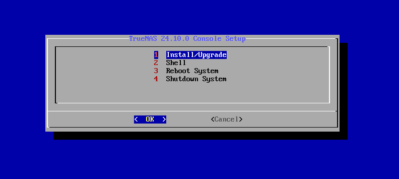
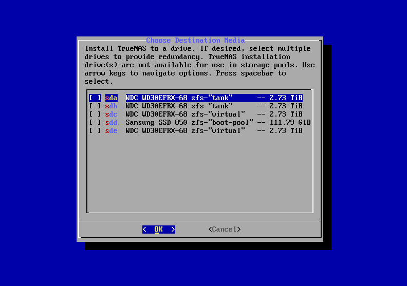
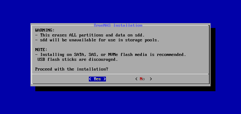
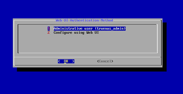
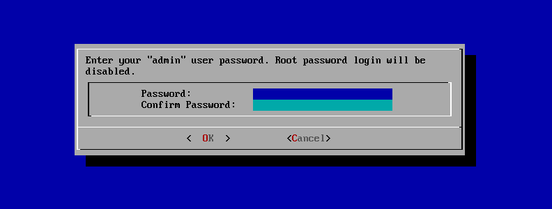
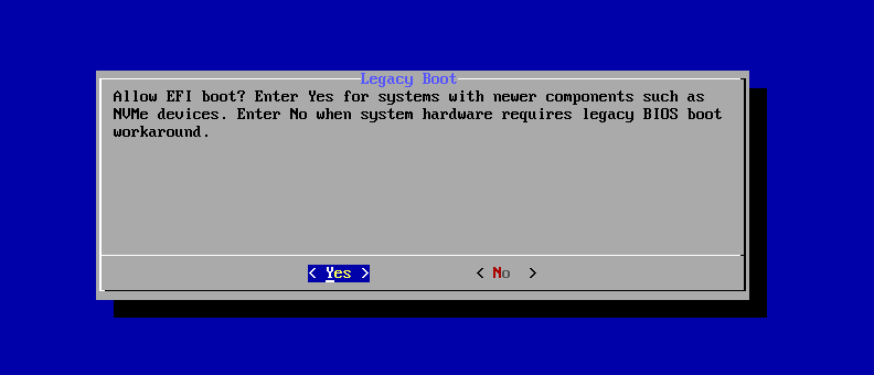
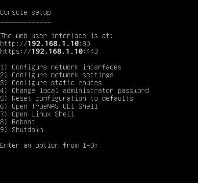
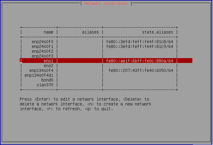
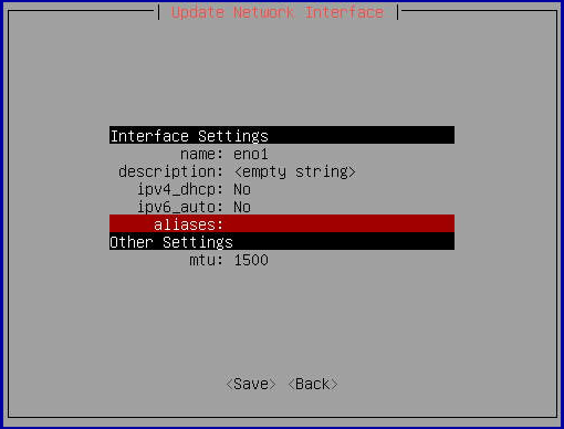
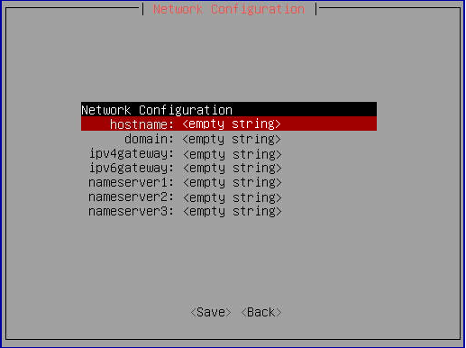
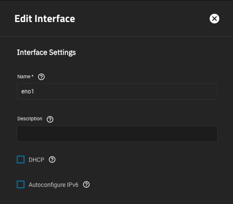
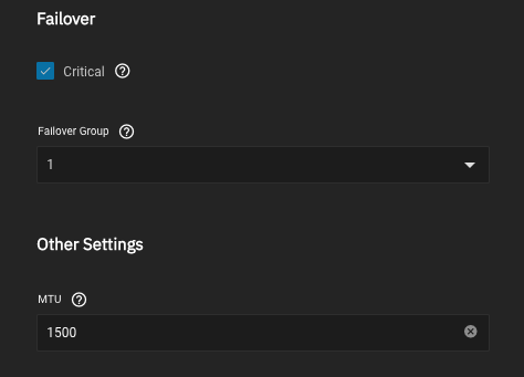
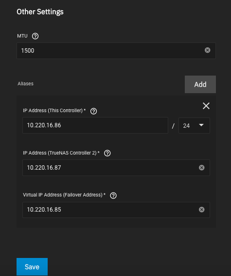
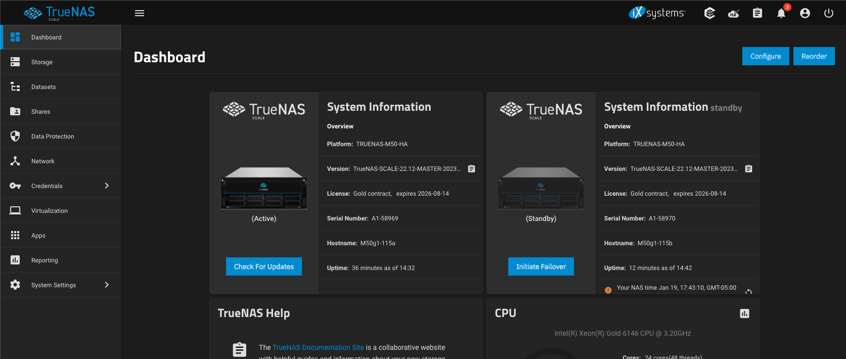
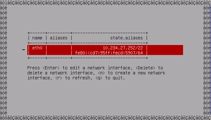
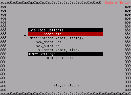
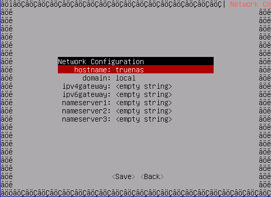


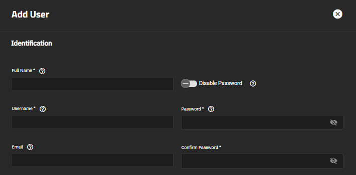
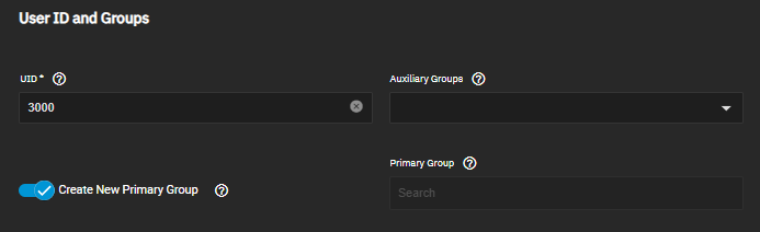
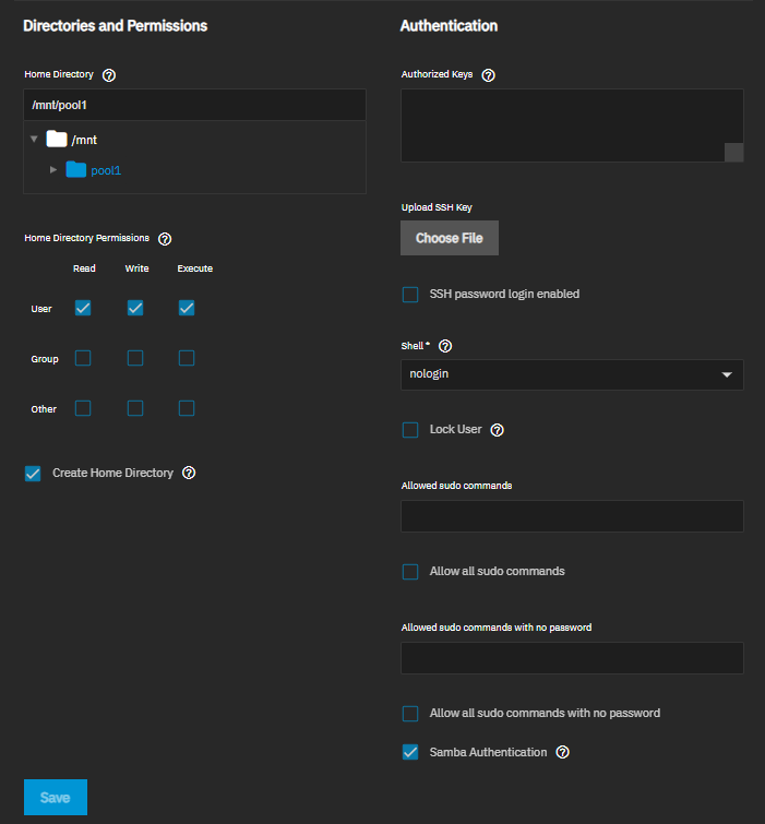
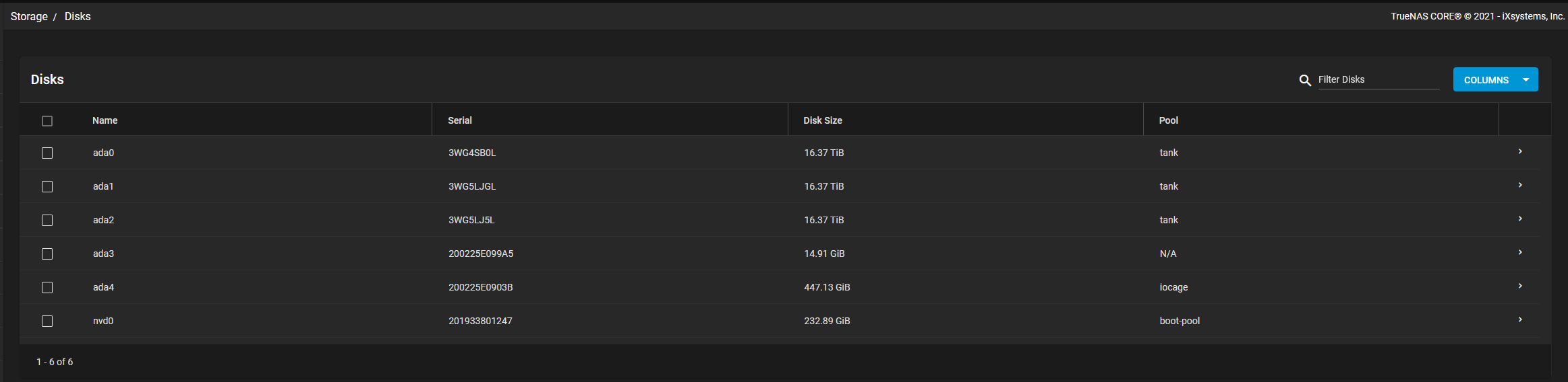
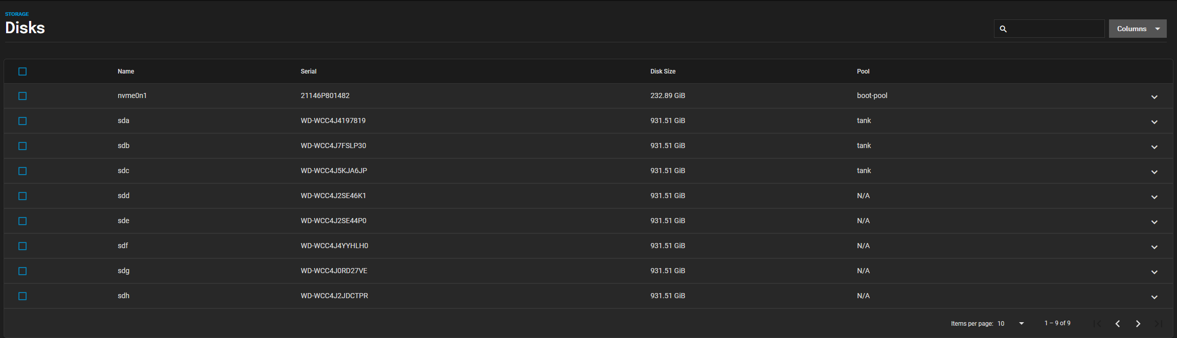
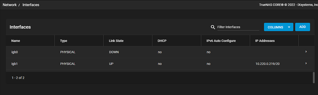
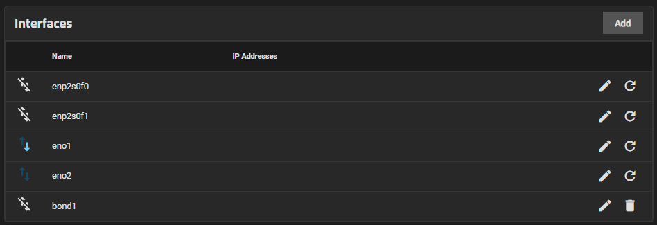
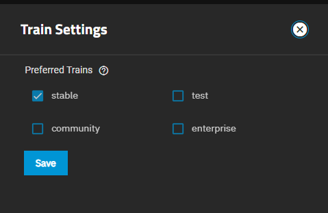
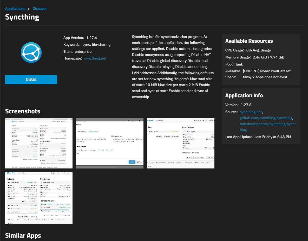
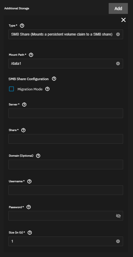
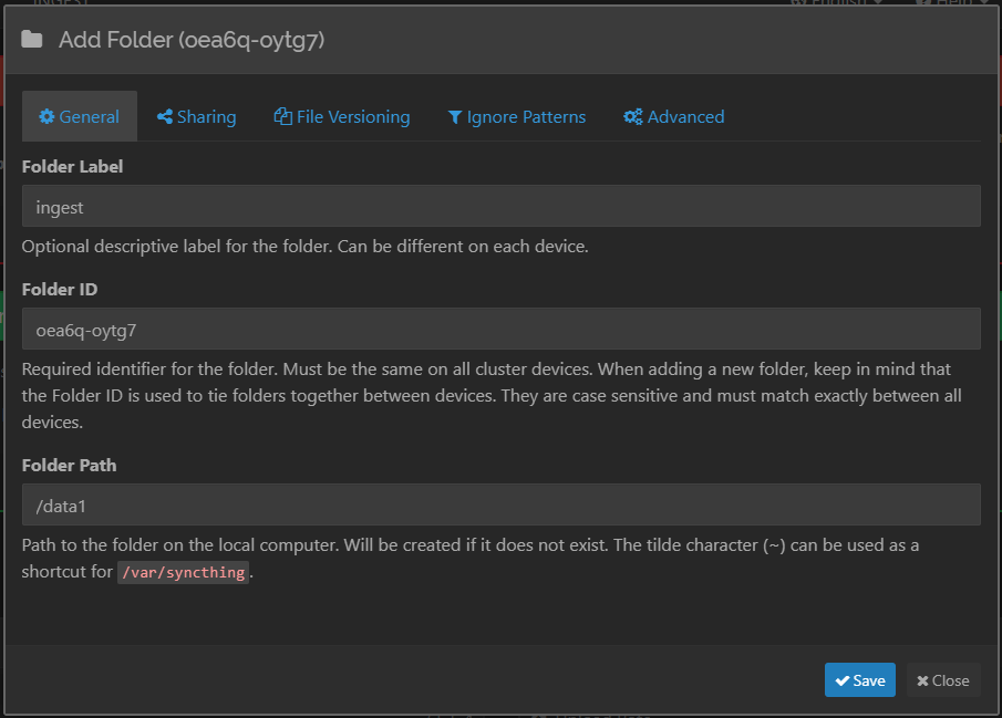
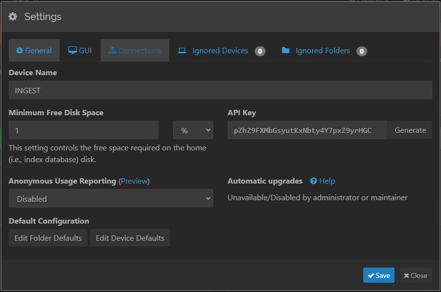
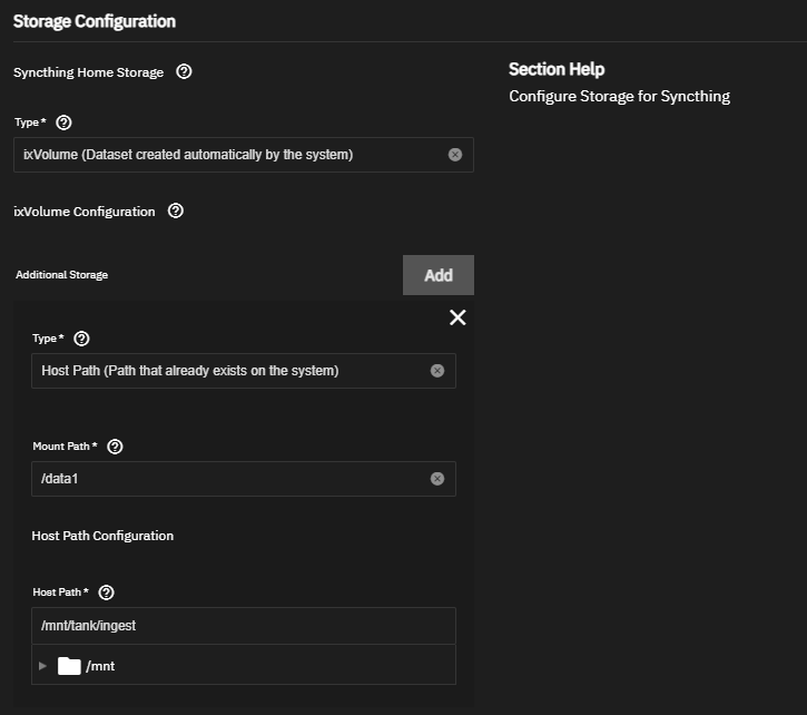
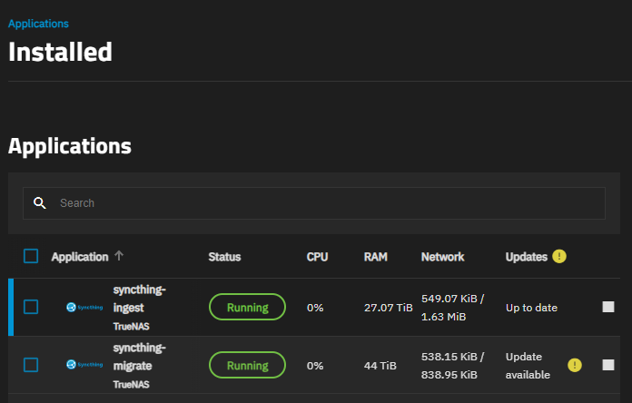
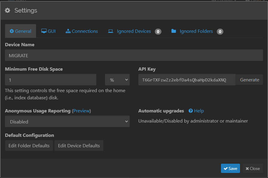
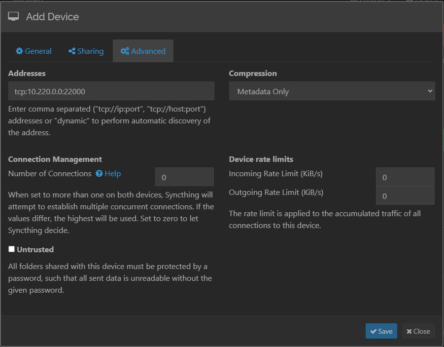
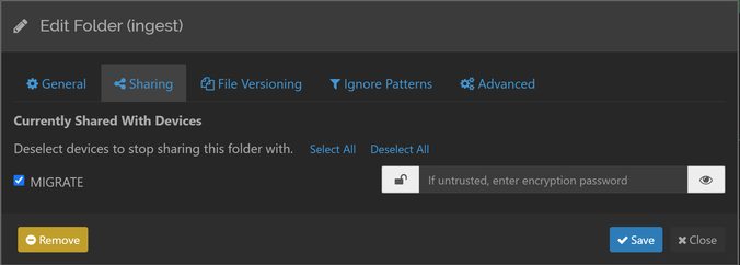
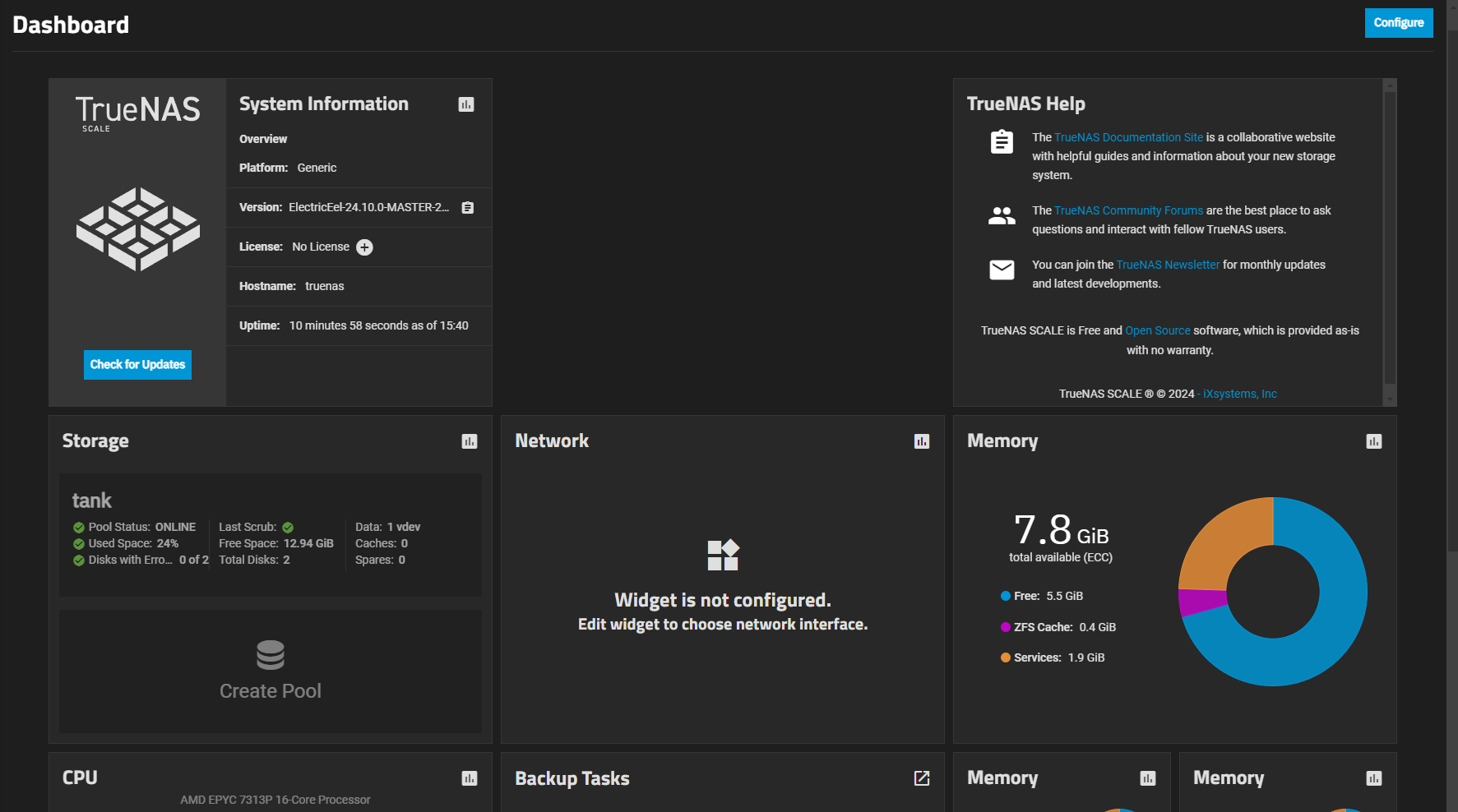
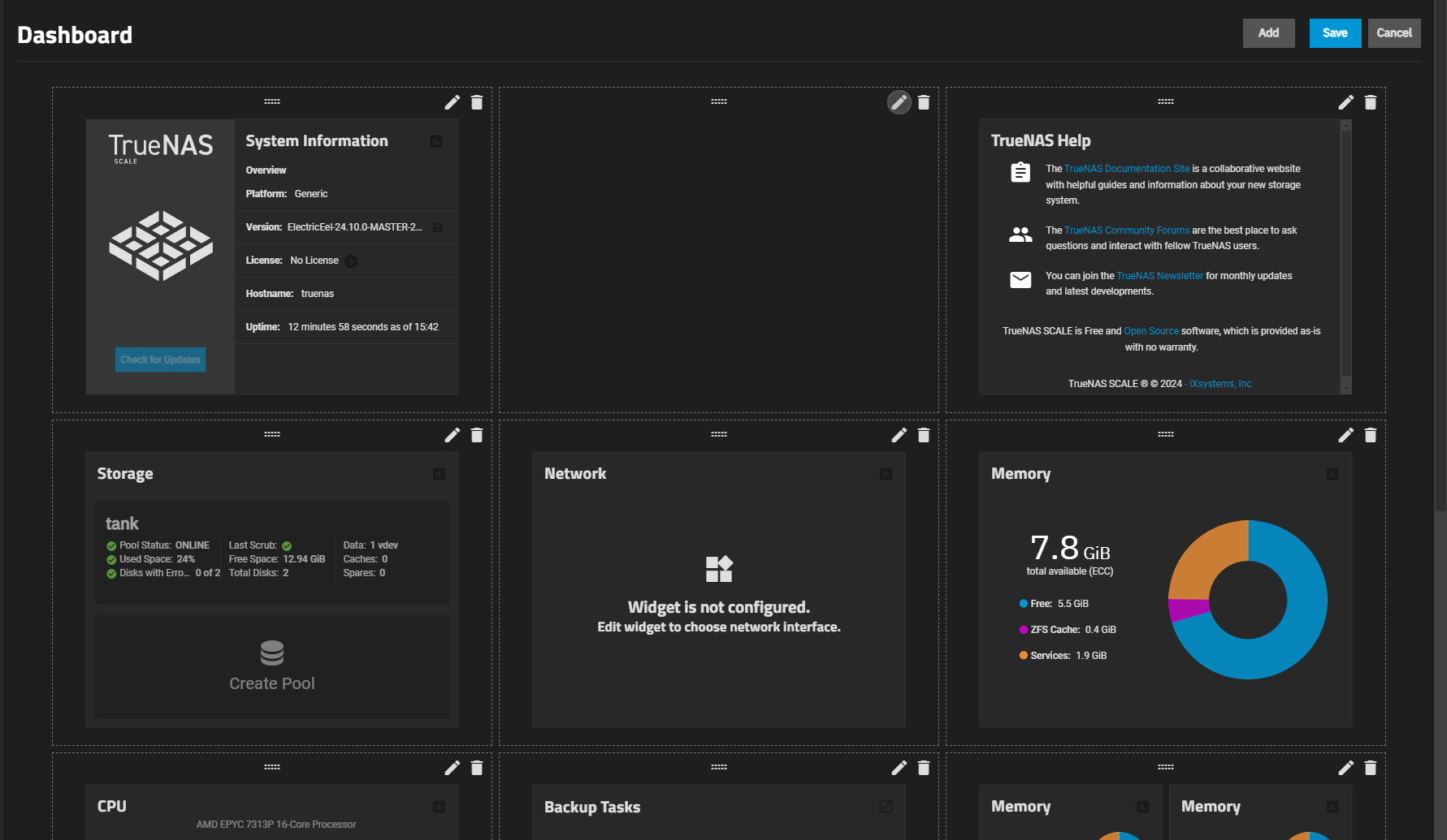


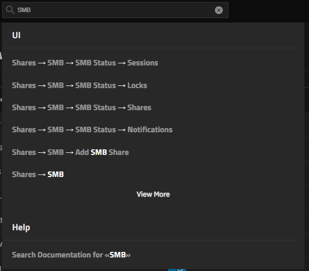
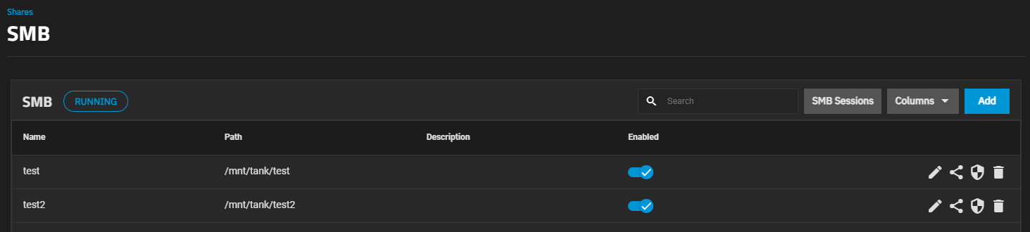
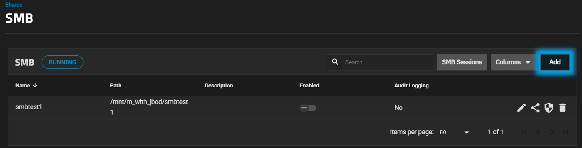
 icon opens a feedback window.
Alternately, go to System > General, find the Support widget, and click File Ticket to see the feedback window.
icon opens a feedback window.
Alternately, go to System > General, find the Support widget, and click File Ticket to see the feedback window.
 icon lets users sign up with and connect to