TrueNAS Documentation Archive
This content follows the TrueNAS 23.10 (Cobia) releases. Archival documentation is provided for reference only and not actively maintained. Use the Product and Version selectors above to view content specific to different TrueNAS software or major version.
Installing SCALE Enterprise (HA)
17 minute read.
Last Modified 2024-03-19 08:38 EDTTrueNAS Enterprise
TrueNAS SCALE Enterprise is generally available with the release of SCALE 22.12.2. Do not attempt to install Enterprise High Availability systems with TrueNAS SCALE until it becomes generally available or the deployment is experimental in nature.
Installing TrueNAS SCALE on High Availability (HA) systems is complicated and should be guided by Enterprise level support. Contact iXsystems Support for assistance whenever attempting to install TrueNAS SCALE on Enterprise HA hardware.
Do NOT use Linux or CLI commands to recover or clean-install the SCALE iso file or configure any initial configuration settings! Incorrect use of CLI commands can further disrupt your system access and can potentially do greater damage to your system. Proceed at your own risk.
This article outlines a procedure to do a clean install of a SCALE Enterprise High Availability (HA) systems using an
HA systems are dual controller systems with the primary controller referred to as controller 1 (sometimes also as controller A) and controller 2 (or controller B).
For best results, we recommend executing this procedure on both controllers at the same time. You can simultaneously install using two USB flash drives inserted into the USB port for each controller (1 and 2) or by establishing an IPMI connection with each controller in separate browser sessions.
Alternately, install and configure controller 1 while keeping controller 2 powered off. When controller 1 is completely configured, power on controller 2 to install TrueNAS and reboot the controller. When controller 2 boots after installing, sync the system configuration from controller 1 to controller 2.
SCALE includes features and functions to help guide with completing the configuration process after installing and getting access to the SCALE web interface.
For a list of SCALE Enterprise (HA) preparation information, see Preparing for SCALE UI Configuration (Enterprise).
Have this information handy to complete this procedure:
- All the assigned network addresses and host names (VIP, controller 1 and 2 IP addresses)
- Other network information including domain name(s), and DNS server, default gateway, alias or other static IP addresses
- The IPMI access addresses for each controller and the administration credentials for IPMI access to these addresses
- SCALE license file provided by iXsystems.
- SCALE Storage Controller 1 (A) and 2 (B) serial numbers (refer to contracts or documentation provided with the system, or contact iXsystems Support and provide your contract number)
When restoring after a clean install, also have ready:HA system controllers each have serial numbers, the lower number assigned is for controller 1 (e.g. of two controller serial numbers assigned A1-12345 and A1-12346, the A1-12345 is for controller 1 and A1-12346 is for controller 2). - Storage data backups to import into the Enterprise HA system.
- System configuration file from the previous TrueNAS install.
For best results, we recommend executing this procedure on both controllers at the same time. You can simultaneously install using two USB flash drives inserted into the USB port for each controller (1 and 2) or by establishing an IPMI connection with each controller in separate browser sessions.
Alternately, install and configure controller 1 while keeping controller 2 powered off. When controller 1 is completely configured, power on controller 2 to install TrueNAS and reboot the controller. When controller 2 boots after installing, sync the system configuration from controller 1 to controller 2.
There are two ways to install the HA dual controller system to ensure controller 1 comes online as the primary controller:
- Install both controller simultaneously beginning with controller 1, then immediately starting the install on controller 2.
- Installing each controller individually to specific points in the installation process.
Simultaneous installation must start with controller 1 so it comes online first. Installing each controller individually follows a particular method to ensure controller 1 comes online as the primary controller.
The sections in this article cover the primary steps as a simultaneous installation:
Download the
iso file from the TrueNAS website and prepare the USB flash drives if not using IPMI for remote access.Log into your IPMI system using the network address assigned to controller 1, and then establish a second connection with controller 2 in a new browser session.
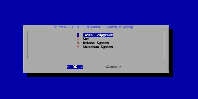
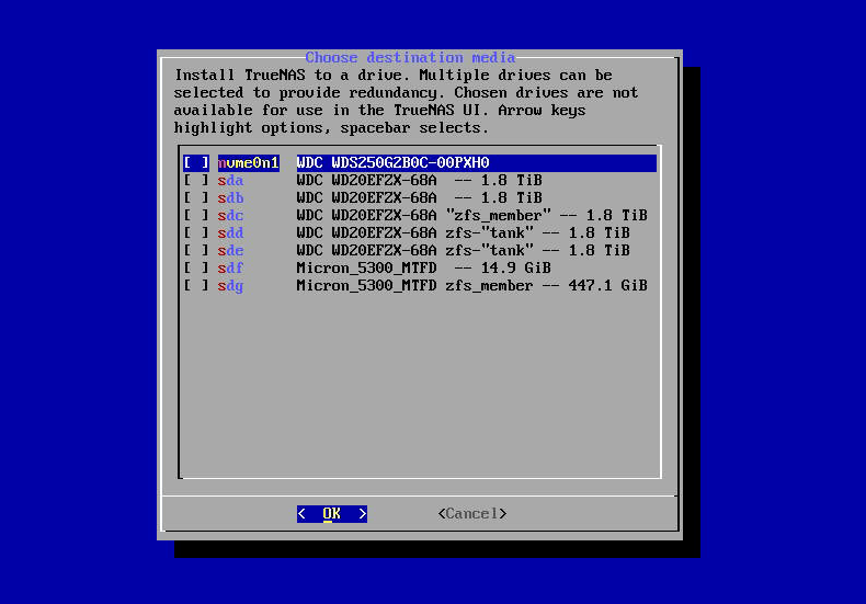
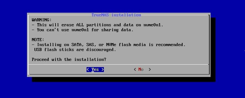
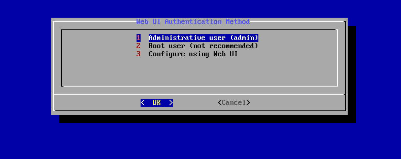
Install SCALE using the
iso file and select the Fresh Install option. Install on controller 1, then immediately begin installing on controller 2 in the other IPMI session to simultaneously install SCALE on both controllers.Disable DHCP, then enter the network settings to controller 1 using the Console Setup Menu. Enter the IP address and netmask assigned to controller 1, then enter the global network settings for host name, domain name, and nameservers.
Use the SCALE UI for system configuration as it has safety mechanisms in place to prevent disrupting network access that could require you to repeat the clean install to access your system. However, if you are experienced with the Console Setup Menu and are using it to configure network settings you can configure the rest of the controller 1 network settings with the Console setup menu.
Log into the SCALE UI for controller 1 to sign the EULA agreement and apply the system HA license.
Disable failover to configure the rest of the network settings and edit the primary network interface on controller 1, and then enable failover.
Complete the minimum storage requirement by adding or importing one pool on controller 1.
Sign in using the Virtual IP (VIP) address.
With controller 2 powered up, on controller 1 sync to peer to complete the install and make controller 2 the standby controller.
The sections that follow describe these steps in detail.
This process of installing each controller sequentially has two methods:
- Install and configure controller 1 up to the point where you are ready to sync to controller 2. When complete, install controller 2 and reboot. After the console setup menu displays, switch back to controller 1 and sync to peer. This synchronizes the completed configuration from controller 1 to controller 2 and keeps controller 1 designated as the primary controller. Or
- Begin installing controller 2 immediately after installing controller 1. When controller 2 finishes installing, power it off and keep it powered down. When finished configuring controller 1, power up controller 2 and wait for it to finish booting up. Switch back to controller 1 and sync the configuration to controller 2.
This section provides an overview of the alternative method to clean install an HA system with controller 2 powered off while installing and configuring controller 1. These steps are nearly identical to the section above but controller 2 is either powered off or not installed while you install and configure controller 1.
- Use either the prepared USB flash drive inserted into a USB port for controller 1 or log into an IPMI session and install SCALE on controller 1. Finish the installation and allow controller 1 to complete its first boot.
- Use either the prepared USB flash drives inserted into a USB port for controller 2 or login into an IPMI session for controller 2 to install SCALE. When the installation finishes, power down controller 2.
- Configure the required network settings on controller 1 with the Console setup menu.
- Log into controller 1 using the IP address assigned to controller 1. Apply the HA license, sign the EULA, and complete the UI configuration to the point where you are ready to sync to peer on controller 1, but do not sync yet.
- Power up controller 2 and wait for it to complete the boot process.
- Log into controller 1, go to System Settings > Failover, and click Sync to Peer. This synchronizes controller 2 with controller 1 and reboots controller 2. Controller 2 becomes the standby controller when it finishes rebooting.
Download the
If you are remote to the system and are installing through an IPMI connection you do not need to save the .iso file to a USB flash drive.
If you are physically present with the TrueNAS SCALE system, burn the
Use this process to install the
If you are doing a clean install from the SCALE.iso file to recover from an issue that requires you to re-install SCALE from the.iso , have your network configuration information ready to use for controller 1 after the installation completes. Do not configure network settings on controller 2. Also have your SCALE system configuration file and data backups handy so you can recover your system settings and import your data into the recovered SCALE clean-install system.
After installing the SCALE
To allow controller 1 to access the UI, you must disable DHCP and add the controller 1 static IP address and netmask as an alias on the primary network interface, and then enter the network settings for host name, domain name, default gateway, and the name servers (1 and 2). You can configure the rest of the HA global network settings in the SCALE web UI.
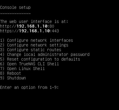
To use the Console setup menu to configure required network settings on controller 1:
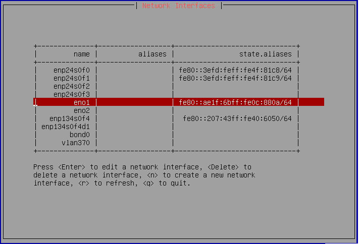
Type 1 and then press Enter to open the Network Interfaces screen.
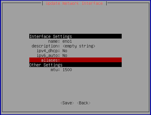
Use either Tab or the arrow keys to select the interface assigned as your primary network interface. If you have more than one interface installed and wired to your network, the primary interface is typically eno1. With the interface highlighted, press Enter to open the Update Network Interface screen.
Tab or arrow down to ipv4_dhcp and change it to no.
Tab or arrow down to the aliases setting and enter the static IP address for controller 1. Tab or arrow down to Save, and then press Enter. A pending network changes notice displays with additional options.
Type a to apply the change, then p to make it persist. Type q to return to the main Console setup menu.
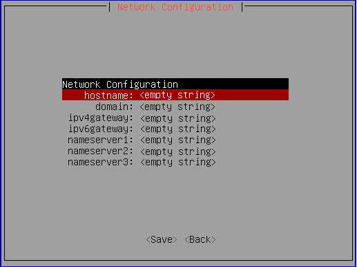
Type 2 and then press Enter to open the Network Configuration screen.
Use either Tab or the arrow keys to select each field. Type the value for each field listed below. Press Enter after each value.
Field Description/Example hostname The host name you assign to controller 1. For example m50-123-1. domain The domain name for the nework controller 1. For example my.companyname.net ipv4gateway The default gateway IP address for your network. nameserver1
nameserver2The IP addresses for your network DNS servers. Use either Tab or the arrow keys to select Save, then type q to return to the main Console setup menu.
Use the SCALE UI to:This section only applies to controller 1. Do not configure settings on controller 2.
- Apply the HA license.
- Complete the network settings.
- Add the first storage pool.
- Sync controller 1 with controller 2.
SCALE UI Enterprise customers see the End User License Agreement (EULA) screen the first time they log in. Sign the agreement to open the main SCALE Dashboard. Apply the system license next.
Go to System Settings > General and click Add License on the Support widget. Copy your license and paste it into the License field, then click Save License. The Reload dialog opens. Click Reload Now. Controller 1 restarts, and displays the EULA for controller 2. Sign the EULA agreement for controller 2, and add the license.
The controller 1 and 2 (or a and b) serial numbers display on the Support widget on the System Settings > General screen.
SCALE Enterprise (HA) systems use three static IP addresses for access to the UI:You must disable the failover service before you can configure network settings!
Only configure network settings on controller 1! When ready to sync to peer, SCALE applies settings to controller 2 at that time.
- VIP to provide UI access regardless of which controller is active. If your system fails over from controller 1 to 2, then fails over back to controller 1 later you might not know which controller is active.
- IP for controller 1. If enabled on your network, DHCP assigns only the controller 1 IP address. If not able to use DHCP, you must change this to the static IP address your network administrator assigned to this controller.
- IP for controller 2. DHCP does not assign the second controller an IP address.
Have your list of network addresses, host and domain names ready so you can complete the network configuration on controller 1 without disruption or system timeouts. SCALE safeguards allow a default of 60 seconds to test and save changes to a network interface before reverting changes. This is to prevent users from breaking their network connection in SCALE.
To configure network settings on controller 1:
Disable the failover service. Go to System Settings > Services locate the Failover service and click edit. Select Disable Failover and click Save.
Edit the global network settings to add any missing network settings or make any changes.
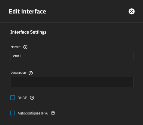
Edit the primary network interface to add failover settings. Go to Network and click on the primary interface eno1 to open the Edit Interface screen for this interface.
a. Turn DHCP off if it is on. Select DHCP to clear the checkbox.
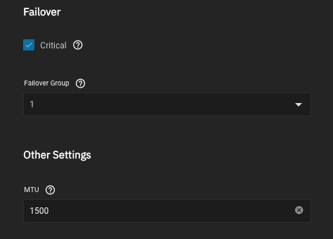
b. Add the failover settings. Select Critical, and then select 1 on the Failover Group dropdown list.
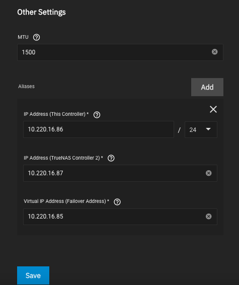
c. Add the virtual IP (VIP) and controller 2 IP. Click Add for Aliases to display the additional IP address fields.
First, enter the IP address for controller 1 into IP Address (This Controller) and select the netmask (CIDR) number from the dropdown list.
Next, enter the controller 2 IP address into IP Address (TrueNAS Controller 2).
Finally, enter the VIP address into Virtual IP Address (Failover Address).
Click Save
Click Test Changes after editing the interface settings. You have 60 seconds to test and then save changes before they revert. If this occurs, edit the interface again.
Create or import a storage pool from a backup. You must have at least one storage pool on controller 1. After saving the storage pool, controller 2 automatically restarts. Wait until it comes back online before syncing controller 1 with controller 2.
For more information on how to create a new pool click here. For more information on how to import a pool click here.
Turn the failover service back on. Go to System Settings > Services locate the Failover service and click edit.
Select Disable Failover to clear the checkmark and turn failover back on, then click Save. The system might reboot. Use IPMI to monitor the status of controller 2 and wait until the controller is back up and running.
Log out of the controller 1 UI, and log in using the VIP address.
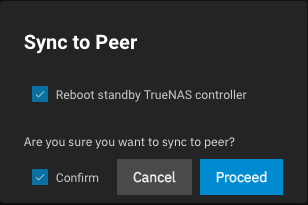
Sync controller 1 and 2. With controller 2 powered on, but not configured, from controller 1 click Sync To Peer. Select Reboot standby TrueNAS controller and Confirm, then click Proceed to start the sync operation. This sync controller 2 with controller 1 which adds the network settings and pool to controller 2.
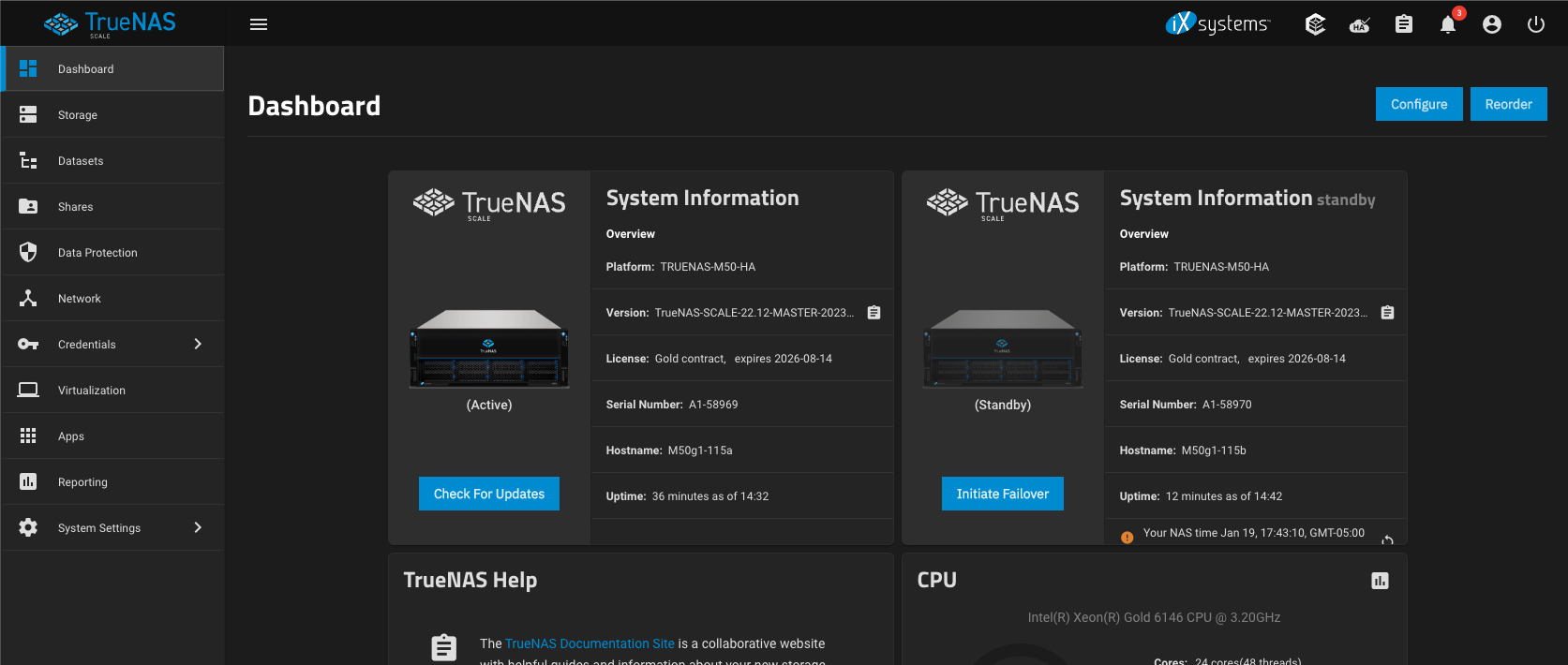
When the system comes back up, log into SCALE using the virtual IP address. The main Dashboard displays two System Information widgets. In standard configurations by iXsystems, Controller 1 shows its serial number and a host name that includes the letter a. Controller 2 is labeled as Standby Controller and shows its serial number and a host name that includes the letter b. Take note of this information.
If controller 2 comes on line as the primary and controller 1 as the standby, you installed and configured these controllers incorrectly. Go to System Settings > Failover, clear the Default TrueNAS Controller option, and click Save. The system reboots and fails over to the current standby controller (in this case, to controller 1). Log back into the UI with the VIP address, go to System Settings > Failover and select Default TrueNAS Controller to make controller 1 the primary controller. and then select Sync to Peer. SCALE makes controller 2 the standby controller and syncs the configuration on controller 1 to controller 2. Click Save.
Related Installation Articles
- Preparing for SCALE UI Configuration
- Preparing for SCALE UI Configuration (Enterprise)
- Preparing for SCALE UI Configuration (Home Users)
- Adding Network Settings
- Installing SCALE
- Using the Console Setup Menu
- Importing a Pool
- Migrating TrueNAS CORE to SCALE (Enterprise HA)
- Configuring SCALE Using the UI
- Shutting Down SCALE Enterprise HA


